EP1244073A2 - Méthode et palpeur pour la validation de documents - Google Patents
Méthode et palpeur pour la validation de documents Download PDFInfo
- Publication number
- EP1244073A2 EP1244073A2 EP02005012A EP02005012A EP1244073A2 EP 1244073 A2 EP1244073 A2 EP 1244073A2 EP 02005012 A EP02005012 A EP 02005012A EP 02005012 A EP02005012 A EP 02005012A EP 1244073 A2 EP1244073 A2 EP 1244073A2
- Authority
- EP
- European Patent Office
- Prior art keywords
- value
- intensity profile
- specific
- security
- determined
- Prior art date
- Legal status (The legal status is an assumption and is not a legal conclusion. Google has not performed a legal analysis and makes no representation as to the accuracy of the status listed.)
- Ceased
Links
Images



Classifications
-
- G—PHYSICS
- G07—CHECKING-DEVICES
- G07D—HANDLING OF COINS OR VALUABLE PAPERS, e.g. TESTING, SORTING BY DENOMINATIONS, COUNTING, DISPENSING, CHANGING OR DEPOSITING
- G07D7/00—Testing specially adapted to determine the identity or genuineness of valuable papers or for segregating those which are unacceptable, e.g. banknotes that are alien to a currency
- G07D7/06—Testing specially adapted to determine the identity or genuineness of valuable papers or for segregating those which are unacceptable, e.g. banknotes that are alien to a currency using wave or particle radiation
- G07D7/12—Visible light, infrared or ultraviolet radiation
- G07D7/1205—Testing spectral properties
Definitions
- the invention relates to a method for the authenticity detection of value and / or security documents according to the preamble of the first independent claim and a corresponding sensor according to the preamble of the second independent claim.
- postage stamps or release stamps which are isolated on letters, parcels and other packaging in the mail sorting machines, are regarded as value and security documents.
- value and security documents are understood to mean banknotes, ID cards, passports, packaging, labels and stickers, travel cards, admission tickets and other tickets, control signs, pledged value signs and shares.
- all printable products and products which are otherwise provided with security features, for example packaging are regarded as value and security documents.
- a sensor known from DE 4117011 A1 is said to be diffuse, weak in intensity Detect radiation as when testing with luminescent features provided banknotes occur.
- the sensor system described there consists of a flared one Optical fiber rod and a processing optics, with the narrow Cross-sectional end of the fiber rod the radiation coming from the measurement object in a large solid angle can be detected.
- the radiation occurs due to the Cross-sectional change at a much smaller angle that on the Opening angle of the following optics is matched from the fiber rod.
- the sensor according to the invention is suitable for mounting in a (high-speed) transport device and can also be designed as a scanner. It is suitable for the detection of a security feature primarily on flat objects.
- a security feature consisting of a color with added up-conversion pigments (also referred to below as anti-Stokes phosphors) is proposed as a detectable security feature. At most, these pigments can also be admixed directly in an applied solution, an applied lacquer, the adhesive or a carrier, for example paper.
- the sensor is advantageous for the detection of a (e.g. printed) Security feature with small dimensions (e.g. 5x5 mm) suitable.
- a (e.g. printed) Security feature with small dimensions (e.g. 5x5 mm) suitable.
- Imprint can be applied within relatively wide limits.
- the required sensor measuring range must therefore capture the entire possible pressure field, although the security feature printed somewhere in that printing area can appear and the security feature is many times smaller than the print area.
- the measurement area can, for example be up to 70 mm in size and detect the small security feature takes place within this large measuring range.
- a spatially resolved detection is preferably carried out in the transport direction.
- the speed in the direction of transport varies from zero to 12 m / s.
- An embodiment as a two-range sensor is preferably also carried out, in which a single illumination illuminates the test object and in which two different spectral ranges are evaluated.
- An additional feature is an integrated or external object detector (optical barrier) can be used, which indicates to the sensor when the object (Security feature) begins and when it ends.
- object detector optical barrier
- Pigments with a rapid increase and a rapid increase are advantageous Fall time (e.g. typically 0.01 - 1 ms) used to detect the to allow desired high speeds.
- Fall time e.g. typically 0.01 - 1 ms
- a laser wavelength above 900 nm is used.
- Other laser wavelengths are also possible.
- the spectral The width of the laser line vary.
- LEDs or others can also be used
- Light sources are used. Multiple parallel beams are used which are relatively close together around the small marked ones Recognize security features.
- the use of a broadband source of electromagnetic radiation possible.
- the laser line according to the invention (produced with normal cylindrical lenses) is produced an irradiance that is highest at the center of the line.
- the laser line is preferably generated with an aspherical cylindrical lens or alternatively with a cylindrical lens array or in another alternative with a sinusoidal wavy lens surface; the irradiance is either here homogeneously distributed over the entire length of the laser line or slightly elevated on Edge (or also in the middle) to the sensitivity variation of the To compensate the receiver over the measuring range.
- the focus in the object plane is designed so that at most Use without a laser line is a slight defocus in order for the Pigments to achieve optimal irradiance.
- the Luminescence efficiency varies with the irradiance and usually has one Optimal at high, but not too high irradiance. If it is too high Irradiance drops the signal strength of the received light again.
- a highly divergent laser beam is advantageously used to get out Cost reasons in a low laser class in the manufacture of the sensor reach.
- the undesired wavelengths of the light source are optically filtered in the spectral detection range. Suppression is preferred to ⁇ 10 -7 , the security feature having to be recognized for at least two periods. Otherwise it is rejected as insufficient.
- the evaluation is carried out using a Analog circuit with sample & hold elements.
- the synchronous amplification evaluates only light signals emitted in phase with the repetition frequency of the Laser light is received.
- the signal evaluation can be further Include details such as Sampling of the signal after on the rising edge a first point in time after the start of the pulse and comparison of this signal with the Signal at a second time after the start of the pulse.
- the elected Time window to the bandpass frequency of the electronics and in particular to the Rise and fall times of the pigments can be adjusted. Control over these signals and time signals are advantageously carried out by a Microprocessor. The same principle can be done during the pulse pause and that Examine the decay behavior of the signal.
- the evaluation can be carried out using a microprocessor integrated or external A / D converter.
- the same evaluation principle can be applied.
- time dependence of the intensity signal at a certain wavelength in the analysis will add an additional level of Security created. Since the time dependence of the signal is very dependent on the on and off Decay behavior, in particular of the response behavior, of the emitted Signal is dependent and this in turn, for example, very easily through the Doping of Yb and Tm in the phosphor can be varied, that offers the method according to the invention or the sensor according to the invention is a very Forgery-proof encryption option for the nominal value of the Security document or the type of security document.
- Security features of a security document are detected with the sensor according to the invention or with the method according to the invention, the security feature using for example an anti-Stokes phosphor (synonyms: anti-Stokes pigment, anti-Stokes phosphor, up-conversion material).
- an anti-Stokes phosphor synonyms: anti-Stokes pigment, anti-Stokes phosphor, up-conversion material.
- the phosphor is able to convert comparatively low-energy infrared (IR) excitation radiation into higher-energy radiation (up-conversion or anti-Stokes effect).
- pigments can also be used, with the addition and Decay behavior, in particular the response behavior of the emitted radiation of the pigment must allow rapid detection of the emitted radiation.
- These can be, for example, photo, cathodophores or electroluminophores.
- the response and decay characteristics of the anti-Stokes phosphor used and in particular the coordination of the excitation and evaluation unit to the response and decay characteristics of the corresponding phosphor largely determine the achievable detection reliability and the possible readout speed of a machine test Lumineszenzmerkmals.
- the response can be characterized, for example, by the time required to reach the 90% value (t 90 ) of the saturation intensity or by the so-called response constant (time required to reach 1 / eth of the stationary luminescence intensity).
- the response time of the anti-Stokes luminescence is allowed not exceed a certain value if one is above the Sensitivity threshold of the detector lies effective luminescence intensity should be secured.
- This effective value of the intensity is determined by the relation determined between the stationary intensity and the response time.
- the signals emitted by the phosphor show due to their a certain intensity profile in certain response and decay behavior Dependence on time.
- the subject of the invention shown here is Realization that anti-Stokes and other luminescence intensities are not only in In terms of their spectral distribution, but also in terms of their temporal Dependency used to analyze authenticity and nominal value recognition can be.
- the relationships between the saturation intensity and the rise and fall times can be varied within a wide range. In particular, it is possible to ensure the low response times required for the implementation of high-speed detection.
- the ytterbium and / or thulium concentrations are varied within certain limits. Further possibilities for influencing the decay and decay characteristics lie in the targeted installation of impurities in the cation or anion partial lattice of the phosphor.
- a laser is used as the beam light source.
- the use of a laser also has the advantage that the scanning line with relatively high radiation intensity mapped on the surface of the document becomes what is not so high when using other beam sources Mass happens.
- the luminance is particularly good when using other beam sources of LEDs then correspondingly lower. Can be used for some applications but this is sufficient.
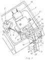
- Figure 1 there is generally a laser 2 in its own in a housing 1 Housing housed, in a manner not shown in the interior a focusing lens 4 is arranged in the housing (see also FIG. 2) and in front the beam opening 3 is a cylindrical lens 5, which corresponds to the beam 6 expands so that it extends to the measurement window 10 in the direction of the arrow is blasted to form an approximately line-shaped scanning line 9.
- a focusing lens 4 is arranged in the housing (see also FIG. 2) and in front the beam opening 3 is a cylindrical lens 5, which corresponds to the beam 6 expands so that it extends to the measurement window 10 in the direction of the arrow is blasted to form an approximately line-shaped scanning line 9.
- the measurement window 10 is closed by a glass pane. Just before this runs towards the measuring window and practically touching the glass pane Examining security document 11 in the direction of arrow 12, with the Security document an authenticity feature 13 in a certain area is arranged.
- the authenticity feature 13 can be in different places, for Example can also be arranged at points 13 'or 13 ".
- the length of the Scanning line 9 is advantageously chosen at least in size, which at most corresponds to the width of the security document, so that by the length of the scanning line 9 is always ensured that this is also a Authenticity feature 13 hits, even if this is in an unexpected place on the Security document 11 is arranged.
- the beam 6 by a Window 8 passes in the area of a panel 7 having several windows.
- the security feature 13 works according to the effect described above and radiates after the excitation by the laser light along the scanning line 9 in the drawn arrow directions an emitted beam 14 through the Measuring window 10 again and passes window 16 in the direction of arrow 15.
- This beam in the direction of arrow 15 is then processed further in an optical head 17 and finally fed to an evaluation unit 18.
- This evaluation unit consists preferably of a photomultiplier (secondary electron multiplier).
- photomultiplier instead of a photomultiplier, other evaluation units can also be used such as photodiodes, a matrix camera with a CCD chip or a CMOS chip works.
- FIG. 1 shows that the document 11 is at a certain distance from the measuring window 10. This is actually not the case, because document 11 should be as dense as possible, if not touching, past the measurement window 10 in the direction of the arrow 12 be moved.
- a so-called document sensor 19 can also be located in the housing 1 be present, which is preferably designed as a light barrier. It will be here a measuring beam 21 directed onto the document to be examined and from it Document reflected in the direction of arrow 22 as a reflection beam and by the Window 20 thrown back.
- the Excitation by the measuring beam 21 also emits radiation into the Cause arrow direction 22, which then penetrates through the measurement window 22.
- the laser optics is only activated, which opens the aforementioned scanning line 9 of the document surface 11 to be examined.
- the evaluation of the authenticity feature advantageously takes place only in the Time in which the document sensor 19 detects the presence of a document ever noticed.
- the scanning line has a width of, for example about 1 to 3 tenths of a mm with a length of 70 mm.
- the wavelength of the laser can be, for example, in the infrared, visible or ultraviolet wavelength range.
- the optical head 17 further includes at least one filter, not shown, the wavelength range evaluated by the evaluation unit 18 limited.
- at least one filter is provided, which the wavelength to be selected selected.
- Such wavelengths can both in the infrared, as well as in the visible or ultraviolet wavelength range lie and are dependent on the one emitted by the authenticity feature 13 Radiation.
- an additional filter be provided, which absorbs the visible light so that it does not affect the To drop the evaluation unit.
- mirrors and / or gratings in the optical head 17 can in addition to and / or instead of the filters mirrors and / or gratings in the optical head 17 be provided, the mirrors and / or gratings located in the beam path select a certain wavelength range.
- the optical head 17 can compensate for different thicknesses Security documents preferably a concave mirror, not shown included, which bundles the radiation emitted by the security feature 13 and this bundling regardless of the amount to be examined Security document implemented.
- the optical head 17 can have a reflection cone, not shown contain, on which the entire beam is bundled.
- This Reflection cone is a metallic coated hollow body, which is in the manner of a Funnel narrows, which carries reflective surfaces on the inside. This ensures to ensure that not only the rays pass through the reflection cone, but also that are mapped onto the receiving element, but also those rays onto the Reception element are mapped to the inner surfaces of the Meet the reflection cone, be reflected there and align with the main beam unite.
- the reflection cone thus amplifies the received light beam essential because not only the direct rays, but obliquely on the Lateral rays hitting the inner walls of the reflection cone Evaluation can be used.
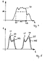
- FIG. 1 A possible spectral distribution of the signal emitted by the security feature 13 is shown schematically in FIG. In the coordinate system, the intensity A is given on the ordinate and the wavelength ⁇ on the abscissa. It is assumed that the laser excitation 34 takes place at a specific wavelength ⁇ 1 and that the authenticity feature 13 then responds with a corresponding up-conversion luminescence 35 with a lower wavelength ⁇ 2 . This up-conversion luminescence 35 is detected and evaluated by the evaluation unit 18.
- the optical head 17 is now such designed that the filters and / or mirrors and / or gratings described above only the signals of a certain wavelength range with a width of 100 nm, preferably with a width of 10 nm.
- the Evaluation unit 18 now detects the intensity of the signal over a specific one Measurement period.
- a measurement period could be, for example, the time which passes until the document sensor 19 receives a new security document detected.
- the measurement period is therefore variable.
- the period of time can also be preset and the Correspond to the time in which a security document is able to emit radiation emit. This time depends on the relative speed at which the Move security documents past the sensor in the direction of the arrow 12.
- Such a signal S1 detected by the evaluation unit 18, is shown in FIG shown schematically in a diagram. It is on the abscissa of the Time t and the intensity A on the ordinate.
- the Signal S1 rises over a certain time, then passes through several local ones Maxima and minima and then falls off again.
- the detected signal S1 is now in a first Embodiment of the invention examined in terms of which Period there is a certain, predetermined intensity threshold A1 exceeds.
- the signal is, for example, in small time units discretized.
- the evaluation unit 18 determines the period in which the Intensity threshold is exceeded, for example as the sum of the time units, in which the intensity is above or at the intensity threshold A1.
- the example shown in FIG. 4 is the length of the period, at which the intensity threshold A1 is exceeded, designated and extends with ⁇ t between the first time t1 and the second time t2.
- the Period of time ⁇ t is then specified by the evaluation unit with a predetermined one Setpoint t (setpoint) compared.
- the security document is recognized as genuine.
- the Measured time period ⁇ t with different target values t (target1), t (target2) etc. is compared. Is the amount of the difference between the determined period ⁇ t and one of the target values t (target1), t (target2) less than or equal to a predetermined value Difference value, then the security document is recognized as genuine and that Security document can be of a certain type or a certain Nominal value can be assigned.
- the banknotes different countries or the stamps with different values be distinguished.
- the ad unit can then output the result of the analysis become.
- a red lamp can light up when a Security document is recognized as fake.
- the recognized value for example a postage stamp
- the measured time-dependent Intensity profile with intensity profile patterns stored in a database compared.
- This exemplary embodiment is intended to be based on the diagram in FIG. 5 are explained.
- the intensity A of the measured signal of a specific, predetermined wavelength range as Function of time t plotted.
- the diagram in FIG. 5 represents two successively measured signals S3 and S5 schematically.
- the first signal S3 belongs to a first security document and the second signal has been S5 measured against a second security document.
- the profiles of both signals have rising edges at the beginning and falling edges at the end.
- the first signal S3 is represented by a first maximum X1 and second maximum X2 and an intermediate minimum in intensity characterized.
- the second signal S5 points between the rising and the falling edge, a first maximum X7 and a second maximum X8 and one intermediate minimum. Both signals differ in that that the maxima and the minima in both intensity and location are different on the timescale.
- the evaluation unit now takes one Comparison of the intensity profile patterns stored in the database with the measured intensity profiles S3 and S5 over a certain period of time in front. For this purpose, the signals are discriminated, for example, and accordingly compared discriminated entries in the database. The result is that Signal S3 the least deviation from the intensity profile pattern M3 and that Signal S5 shows the smallest deviation from the intensity profile pattern M5. is the deviation (i.e.
- Evaluation unit 18 recognized that the security document with the signal S3 is genuine and a certain nominal value which is assigned to the pattern M3, corresponds, and analogously, that the security document with the signal S5 is genuine and a certain nominal value which is assigned to the pattern M5, equivalent. If the deviation is not greater than a specific, fixed one Sum threshold, then the corresponding security document as Counterfeit detected. Analogous to the previously described embodiment of the Invention can be the result of analyzing the signals in a display unit being represented.
- the following is intended to be based on of the signals S7 and S8 shown in FIG. 6 are explained.
- This corresponds to the representation of the signals of the representation chosen in Figures 4 and 5.
- the two signals shown those of different, successively measured Security documents originate from the fact that the rise of the emitted signal is different.
- This takes advantage of this evaluation method now described. Between two fixed ones The evaluation unit calculates the mean times t4 and t5 or t4 'and t5' Slope (first derivative) of the signal. The slope is in Figure 6 above the respective signal curve and drawn with G1 (signal S7) and G3 (signal S8) designated.
- the slopes G1 and G3 are included in a database stored target increase value G (target1), G (target2) etc. Is the Deviation from a certain target increase value smaller than a certain, predefined increase threshold value, it is recognized that the corresponding Security document is real. It can also be of a certain type or one certain nominal value. Corresponds to the measured Slope value not a target slope value from the database in corresponding limits, then the corresponding security document is considered Counterfeit detected.
- the corresponding deviation values can also be provided in the database in this way, that it matches the target value or the intensity profile pattern or the target increase value, which is the smallest deviation from the respective determined value owns are assigned. Then the corresponding difference with the corresponding specific difference value or total threshold value or Rise threshold compared.
- the basis of all methods for the authenticity detection of Security features on value and security documents is the knowledge that the on and / or the decay time, especially the decay time, of emitted Radiation is an essential characteristic of the security element.
- This Characteristic is very forgery-proof, because a variation of the arrival and Cooldowns of phosphors that emit radiation, for example, by the change in the doping or by the incorporation of impurities in the Crystal lattice is made that is difficult to detect and difficult for a forger are imitable.
- the signals in one certain, fixed predetermined larger wavelength range in addition to evaluating the intensity of the signal in a particular Wavelength range with a very limited size the signals in one certain, fixed predetermined larger wavelength range.
- This is the optical head 17 with the corresponding filters and / or mirrors and / or Bars equipped.
- that of the Security element emitted electromagnetic radiation depending on the wavelength in the larger wavelength range by the evaluation unit 18 recorded.
- Several emission lines are generally recorded, such as this is shown, for example, on the basis of lines 35 and 36 in FIG. 3.
- the evaluation unit determines as a measure of the intensity of the respective Line the area under the respective emission line. After that, the relationship the intensities of two selected lines and one Intensity ratio setpoint compared that is stored in the database.
- the Matching the setpoint can be used as an additional criterion for detection the authenticity or a nominal value, because the variation of the arrival and Cooldowns of the up-conversion luminescence also the Intensity ratios can be varied.
- a can be used as a measure of the intensity.
- Emission line also the intensity value at the point of the maximum of the respective Line can be used.
- the system is based on the schematic drawing shown in Figure 7 explained.
- the sensor unit 50 contains a first sensor element 53, a second one Sensor element 54, a third sensor element 55 and a stamp and Release element 57, wherein the mailpiece contains the elements of sensor unit 50 in in the order mentioned.
- the mail item is analyzed in the first sensor element 53 in such a way that whether it contains stamps or a release stamp and if so, on which one Place of the mailing.
- Known for this purpose in the sensor element 53 methods based on image recognition are used. Won this Information on whether there are stamps or release stamps and on which ones Place the stamps or the release stamps are arranged on the third sensor element 55 passed on. Are neither stamp nor The stamp will contain a release stamp on the mailpiece discarded.
- the mail item is then conveyed on to the second sensor element 54.
- This sensor element checks using image recognition methods and a weight measurement, which type of mail item is present. In doing so for example, different types of cards and letters according to their size and their Weight and different types of packages and parcels also according to their size and their weight. Also that of the second sensor element Information obtained is forwarded to the third sensor element 55.
- the third sensor element 55 now takes over after the mail item arrives this element has been forwarded, analogous to one or more of the above Exemplary embodiments described the analysis of the security elements of the Postage stamp or release stamp.
- the third sensor element has one Structure that is analogous to the sensor element shown in Figure 1.
- the at least one stamp or the release stamp is issued by the third Sensor element 55 examined for authenticity and / or value.
- a hollow mirror mentioned above in the beam path of the emitted steel is advantageous because the heights of the mail items are different do not affect the focus of the emitted beam.
- the at least one stamp and / or the release stamp are compared. is the value determined is greater than or equal to that based on the type of mail item expected value, then the mail item in the release and stamp unit 57 released and for example with a canceling postmark Mistake. If the determined value is smaller than the expected value, the The mail item is sorted out and marked, for example, in order to Initiate payment of a cash on delivery.
- the embodiment described above can also without Valuation and comparison are carried out. Then the value of the Release stamp or the at least one stamp in another way examined and with a setpoint dependent on the type of mail item be compared.
- the sensor unit 50 guides by means of the third Sensor element 53 only authenticity detection in the at least one Postage stamp or the release stamp contained security features and by. In this case, the second sensor element 54 is omitted.
- the security element in the form of pigments, which when stimulated by electromagnetic radiation of a certain wavelength radiation in one emit other wavelength range, are in a known manner in the insert or apply at least one stamp.
- the release stamp contains in its color the corresponding pigments.
Landscapes
- Physics & Mathematics (AREA)
- Health & Medical Sciences (AREA)
- General Health & Medical Sciences (AREA)
- Toxicology (AREA)
- Spectroscopy & Molecular Physics (AREA)
- General Physics & Mathematics (AREA)
- Inspection Of Paper Currency And Valuable Securities (AREA)
Applications Claiming Priority (2)
| Application Number | Priority Date | Filing Date | Title |
|---|---|---|---|
| DE10113268.9A DE10113268B4 (de) | 2001-03-16 | 2001-03-16 | Sensor für die Echtheitserkennung von Sicherheitsmerkmalen auf Wert und/oder Sicherheitsdokumenten |
| DE10113268 | 2001-03-16 |
Publications (2)
| Publication Number | Publication Date |
|---|---|
| EP1244073A2 true EP1244073A2 (fr) | 2002-09-25 |
| EP1244073A3 EP1244073A3 (fr) | 2004-06-09 |
Family
ID=7678070
Family Applications (1)
| Application Number | Title | Priority Date | Filing Date |
|---|---|---|---|
| EP02005012A Ceased EP1244073A3 (fr) | 2001-03-16 | 2002-03-06 | Méthode et palpeur pour la validation de documents |
Country Status (3)
| Country | Link |
|---|---|
| US (1) | US7092583B2 (fr) |
| EP (1) | EP1244073A3 (fr) |
| DE (1) | DE10113268B4 (fr) |
Cited By (4)
| Publication number | Priority date | Publication date | Assignee | Title |
|---|---|---|---|---|
| EP1673736A1 (fr) * | 2003-10-08 | 2006-06-28 | Giesecke & Devrient GmbH | Systeme de verification des caracteristiques de securite de papiers-valeurs |
| WO2007057641A1 (fr) * | 2005-11-16 | 2007-05-24 | Ncr Corporation | Lecteur d'étiquette sécurisée |
| WO2014067922A1 (fr) * | 2012-10-31 | 2014-05-08 | Bundesdruckerei Gmbh | Procédé et dispositif de vérification d'un élément de sécurité |
| EP2504819B1 (fr) | 2009-11-23 | 2016-06-29 | Honeywell International Inc. | Appareil d'authentification pour documents de valeur en mouvement |
Families Citing this family (29)
| Publication number | Priority date | Publication date | Assignee | Title |
|---|---|---|---|---|
| US7162035B1 (en) | 2000-05-24 | 2007-01-09 | Tracer Detection Technology Corp. | Authentication method and system |
| DE10150457A1 (de) * | 2001-10-16 | 2003-04-30 | Deutsche Post Ag | Verfahren und Vorrichtung zur Bearbeitung von auf Oberflächen von Postsendungen befindlichen graphischen Informationen |
| WO2003105075A1 (fr) * | 2002-06-07 | 2003-12-18 | Trustees Of Boston University | Systeme et procedes d'authentification de produits et documents |
| DE10256114A1 (de) | 2002-11-29 | 2004-06-09 | Giesecke & Devrient Gmbh | Verfahren und Vorrichtung zur Prüfung von Wertdokumenten |
| DE10322794B4 (de) * | 2003-05-19 | 2011-08-11 | Bundesdruckerei GmbH, 10969 | Sensor für die Echtheitserkennung eines lumineszierenden Sicherheitselements eines Wertdokuments, Wertdokument sowie Verfahren zur Herstellung eines Wertdokuments |
| US7173701B2 (en) * | 2004-02-13 | 2007-02-06 | Kaiwood Technology Co., Ltd. | CCD-based biochip reader |
| DE102004022995A1 (de) * | 2004-05-10 | 2005-12-08 | Bundesdruckerei Gmbh | Verfahren und Vorrichtung zur Echtheitserkennung von Sicherheitsmerkmalen auf Wert- und/oder Sicherheitsdokumenten |
| DE102004024620A1 (de) * | 2004-05-18 | 2005-12-08 | Giesecke & Devrient Gmbh | Vorrichtung und Verfahren zur Prüfung von Banknoten |
| US7919325B2 (en) | 2004-05-24 | 2011-04-05 | Authentix, Inc. | Method and apparatus for monitoring liquid for the presence of an additive |
| EP1647947A1 (fr) * | 2004-10-14 | 2006-04-19 | Giesecke & Devrient GmbH | Appareil et procédé pour vérifier un élément de securité luminescent |
| DE102004049998A1 (de) * | 2004-10-14 | 2006-04-20 | Giesecke & Devrient Gmbh | Vorrichtung und Verfahren zur visuellen Darstellung von Meßwerten |
| US20070044679A1 (en) * | 2005-08-30 | 2007-03-01 | Petrik Viktor I | White-fluorescent anti-stokes compositions and methods |
| DE102007019107A1 (de) * | 2007-04-23 | 2008-10-30 | Giesecke & Devrient Gmbh | Verfahren und Vorrichtung zur Prüfung von Wertdokumenten |
| EP2240333A2 (fr) * | 2008-02-05 | 2010-10-20 | Bayer Technology Services GmbH | Élément de sécurité |
| US7995196B1 (en) | 2008-04-23 | 2011-08-09 | Tracer Detection Technology Corp. | Authentication method and system |
| FR2940179B1 (fr) | 2008-12-23 | 2017-06-02 | Arjowiggins | Document de securite comportant au moins une image combinee et un moyen de revelation, et procede associe. |
| DE102009026488A1 (de) | 2009-05-26 | 2010-12-02 | Bundesdruckerei Gmbh | Mikrosystem zur Erkennung vorbestimmter Merkmale von Wertpapieren, Sicherheitsdokumenten oder sonstigen Produkten |
| JP2014519130A (ja) * | 2011-06-06 | 2014-08-07 | シクパ ホルディング ソシエテ アノニム | インライン減衰時間スキャナ |
| US10275969B2 (en) | 2012-03-09 | 2019-04-30 | United States Postal Service | Method and system for item authentication and customization |
| US9291559B2 (en) | 2012-03-09 | 2016-03-22 | United States Postal Service | Method and system for item authentication and customization |
| US9053596B2 (en) * | 2012-07-31 | 2015-06-09 | De La Rue North America Inc. | Systems and methods for spectral authentication of a feature of a document |
| DE102012025263A1 (de) | 2012-12-21 | 2014-06-26 | Giesecke & Devrient Gmbh | Sensor und Verfahren zur Prüfung von Wertdokumenten |
| US9291564B2 (en) * | 2013-04-05 | 2016-03-22 | Datacolor Holding Ag | Method and apparatus for aligning measured spectral radiance factors among different instruments |
| TR201811660T4 (tr) * | 2013-05-28 | 2018-09-21 | Sicpa Holding Sa | İşaret okuma cihazlarındaki sıralı aydınlatma. |
| DE102016120979A1 (de) | 2016-11-03 | 2018-05-03 | Bundesdruckerei Gmbh | Verfahren zur Echtheitsprüfung eines Sicherheitsmerkmals und Anordnung zur Echtheitsprüfung eines Sicherheitsdokuments mit einem Sicherheitsmerkmal |
| DE102018007289A1 (de) * | 2018-09-14 | 2020-03-19 | Giesecke+Devrient Currency Technology Gmbh | Wertdokumentsystem |
| DE102019210762A1 (de) * | 2019-07-19 | 2021-01-21 | Bundesdruckerei Gmbh | Verfahren zur Auswertung von flüchtigen nicht resistenten Anti-Stokes-Lumineszenzstoffen auf Wertdokumenten |
| DE102019005656A1 (de) * | 2019-08-12 | 2021-02-18 | Giesecke+Devrient Currency Technology Gmbh | Verfahren und Vorrichtung zum Prüfen von Wertdokumenten |
| DE102023108014A1 (de) * | 2023-03-29 | 2024-10-02 | Technische Hochschule Rosenheim, Körperschaft des öffentlichen Rechts | Inspektionsvorrichtung und Verfahren zur optischen Erfassung von Eigenschaften eines auf einer Fördereinrichtung in eine Transportrichtung transportierten Objektes mittels Fluoreszenzanregung |
Family Cites Families (18)
| Publication number | Priority date | Publication date | Assignee | Title |
|---|---|---|---|---|
| DE1449107B1 (de) * | 1961-04-15 | 1969-09-04 | Telefunken Patent | Verfahren zum Abtasten von Aufzeichnungsträgern,deren Abtastfeld mit lumineszierenden Zeichen versehen ist,insbesondere für selbsttätige Sortierung von Postsendungen |
| ES503247A0 (es) * | 1980-05-30 | 1982-05-16 | Gao Ges Automation Org | Perfeccionamientos en la fabricacion de papel dotado de mar-cas de seguridad |
| GB2095822B (en) * | 1981-03-30 | 1984-10-10 | Ramley Engineering Co Ltd | Identifying objects by detecting decaying phosphorescence from phosphor coating thereon |
| FR2593840B1 (fr) * | 1986-02-05 | 1989-07-13 | Arjomari Prioux | Papier de securite comportant un moyen de marquage et de reconnaissance fluorescent |
| DE4022020A1 (de) * | 1990-07-11 | 1992-01-16 | Gao Ges Automation Org | Vorrichtung und verfahren zur pruefung von dokumenten |
| US5574790A (en) * | 1993-09-27 | 1996-11-12 | Angstrom Technologies, Inc. | Fluorescence authentication reader with coaxial optics |
| US5917925A (en) * | 1994-04-14 | 1999-06-29 | Moore; Lewis J. | System for dispensing, verifying and tracking postage and other information on mailpieces |
| EP0760565B1 (fr) * | 1995-08-28 | 1998-07-08 | Ofra Feldbau | Dispositif et procédé pour l'authentification de l'envoi et du contenu des documents |
| GB9607788D0 (en) * | 1996-04-15 | 1996-06-19 | De La Rue Thomas & Co Ltd | Document of value |
| US6091563A (en) | 1997-09-26 | 2000-07-18 | Iomega Corporation | Latent illuminance discrimination marker system for data storage cartridges |
| US6264107B1 (en) * | 1997-09-26 | 2001-07-24 | Iomega Corporation | Latent illuminance discrimination marker system for authenticating articles |
| US6201662B1 (en) | 1998-09-25 | 2001-03-13 | Iomega Corporation | Latent illuminance discrimination marker with reflective layer for data storage cartridges |
| US6181662B1 (en) | 1997-09-26 | 2001-01-30 | Iomega Corporation | Latent irradiance discrimination method and marker system for cartridgeless data storage disks |
| US5974150A (en) * | 1997-09-30 | 1999-10-26 | Tracer Detection Technology Corp. | System and method for authentication of goods |
| US6155491A (en) * | 1998-05-29 | 2000-12-05 | Welch Allyn Data Collection, Inc. | Lottery game ticket processing apparatus |
| US6136752A (en) * | 1998-10-02 | 2000-10-24 | Eastman Kodak Company | Receiver having authenticating marks |
| US6155604A (en) * | 1999-05-27 | 2000-12-05 | Greene; Jonathan D | Coatings and ink designs for negotiable instruments |
| DK1158459T3 (da) * | 2000-05-16 | 2009-02-23 | Sicpa Holding Sa | Fremgangsmåde, indretning og sikkerhedssystem, alle til at berigtige en markering |
-
2001
- 2001-03-16 DE DE10113268.9A patent/DE10113268B4/de not_active Expired - Lifetime
-
2002
- 2002-03-06 EP EP02005012A patent/EP1244073A3/fr not_active Ceased
- 2002-03-15 US US10/099,472 patent/US7092583B2/en not_active Expired - Lifetime
Cited By (6)
| Publication number | Priority date | Publication date | Assignee | Title |
|---|---|---|---|---|
| EP1673736A1 (fr) * | 2003-10-08 | 2006-06-28 | Giesecke & Devrient GmbH | Systeme de verification des caracteristiques de securite de papiers-valeurs |
| WO2007057641A1 (fr) * | 2005-11-16 | 2007-05-24 | Ncr Corporation | Lecteur d'étiquette sécurisée |
| US7462840B2 (en) | 2005-11-16 | 2008-12-09 | Ncr Corporation | Secure tag reader |
| EP2504819B1 (fr) | 2009-11-23 | 2016-06-29 | Honeywell International Inc. | Appareil d'authentification pour documents de valeur en mouvement |
| WO2014067922A1 (fr) * | 2012-10-31 | 2014-05-08 | Bundesdruckerei Gmbh | Procédé et dispositif de vérification d'un élément de sécurité |
| US10255515B2 (en) | 2012-10-31 | 2019-04-09 | Bundesdruckerei Gmbh | Method and device for checking a security element |
Also Published As
| Publication number | Publication date |
|---|---|
| US7092583B2 (en) | 2006-08-15 |
| US20020131618A1 (en) | 2002-09-19 |
| EP1244073A3 (fr) | 2004-06-09 |
| DE10113268B4 (de) | 2021-06-24 |
| DE10113268A1 (de) | 2002-09-19 |
Similar Documents
| Publication | Publication Date | Title |
|---|---|---|
| DE10113268B4 (de) | Sensor für die Echtheitserkennung von Sicherheitsmerkmalen auf Wert und/oder Sicherheitsdokumenten | |
| EP2275998B1 (fr) | Dispositif de verification de documents de valeur | |
| EP1160719B1 (fr) | Capteur pour l'authentification de signets sur des documents | |
| EP2011092B1 (fr) | Dispositif et procédé d'examen optique de documents de valeur | |
| EP4014210B1 (fr) | Procédé et dispositif d'examen de documents de valeur | |
| DE60101210T2 (de) | Gerät und verfahren zum überprüfen eines dokumentes | |
| EP1112555B1 (fr) | Procédé et dispositif pour contrôler l'état des papiers de valeur utilisant de mesure fond noir et fond clair. | |
| EP2377104B1 (fr) | Dispositif et procédé de détection de lumière réfléchie et/ou émise par un objet | |
| WO2001061654A2 (fr) | Procede et dispositifs pour le controle d'authenticite d'objets imprimes | |
| EP1265198B1 (fr) | Dispositif et méthode pour analyser des documents | |
| EP3503049B1 (fr) | Dispositif et procédé de détection d'une caractéristique de sécurité lisible par machine d'un document de valeur | |
| EP1456819B1 (fr) | Procedes et dispositifs pour verifier l'authenticite d'articles en feuille | |
| DE102008047636A1 (de) | Vorrichtung zur maschinellen Echtheitsüberprüfung von Wert- und Sicherheitsdokumenten | |
| EP3400583B1 (fr) | Authentification de documents de valeur | |
| WO2007025740A1 (fr) | Procede et dispositif pour verifier l'authenticite de billets de banque | |
| DE4117011A1 (de) | Optischer sensor | |
| DE102009032227A1 (de) | Verfahren für die Prüfung von Wertdokumenten | |
| DE19701513C2 (de) | Prüfverfahren und Prüfeinrichtung für Echtheitskontrolle von Echtheitsmarken | |
| EP4000049B1 (fr) | Dispositif capteur de photoluminescence servant à vérifier une propriété de sécurité d'un objet et procédé de calibrage d'un dispositif capteur de photoluminescence | |
| EP4104148B1 (fr) | Capteur optique destiné à l'examen de documents de valeur | |
| WO2025061233A1 (fr) | Dispositif de capteur pour tester une caractéristique de sécurité avec luminescence stimulée optiquement, appareil d'essai et procédé d'essai | |
| EP4548320A1 (fr) | Dispositif et procédé permettant de tester des échantillons plats | |
| DE10160580A1 (de) | Verfahren und Vorrichtung für die Überprüfung der Echtheit von Blattgut | |
| EP2323108A1 (fr) | Dispositif et procédé de vérification de éléments de sécurité contenues dans la structure fibreuse d'objets plats en papier |
Legal Events
| Date | Code | Title | Description |
|---|---|---|---|
| PUAI | Public reference made under article 153(3) epc to a published international application that has entered the european phase |
Free format text: ORIGINAL CODE: 0009012 |
|
| AK | Designated contracting states |
Kind code of ref document: A2 Designated state(s): AT BE CH CY DE DK ES FI FR GB GR IE IT LI LU MC NL PT SE TR |
|
| AX | Request for extension of the european patent |
Free format text: AL;LT;LV;MK;RO;SI |
|
| PUAL | Search report despatched |
Free format text: ORIGINAL CODE: 0009013 |
|
| AK | Designated contracting states |
Kind code of ref document: A3 Designated state(s): AT BE CH CY DE DK ES FI FR GB GR IE IT LI LU MC NL PT SE TR |
|
| AX | Request for extension of the european patent |
Extension state: AL LT LV MK RO SI |
|
| 17P | Request for examination filed |
Effective date: 20040812 |
|
| RAP1 | Party data changed (applicant data changed or rights of an application transferred) |
Owner name: BUNDESDRUCKEREI GMBH |
|
| 17Q | First examination report despatched |
Effective date: 20041206 |
|
| AKX | Designation fees paid |
Designated state(s): AT BE CH CY DE DK ES FI FR GB GR IE IT LI LU MC NL PT SE TR |
|
| STAA | Information on the status of an ep patent application or granted ep patent |
Free format text: STATUS: THE APPLICATION HAS BEEN REFUSED |
|
| 18R | Application refused |
Effective date: 20111124 |