EP2504819B1 - Appareil d'authentification pour documents de valeur en mouvement - Google Patents
Appareil d'authentification pour documents de valeur en mouvement Download PDFInfo
- Publication number
- EP2504819B1 EP2504819B1 EP10832310.6A EP10832310A EP2504819B1 EP 2504819 B1 EP2504819 B1 EP 2504819B1 EP 10832310 A EP10832310 A EP 10832310A EP 2504819 B1 EP2504819 B1 EP 2504819B1
- Authority
- EP
- European Patent Office
- Prior art keywords
- value document
- detector element
- image
- electronic signal
- photodetector
- Prior art date
- Legal status (The legal status is an assumption and is not a legal conclusion. Google has not performed a legal analysis and makes no representation as to the accuracy of the status listed.)
- Revoked
Links
Images

Classifications
-
- G—PHYSICS
- G07—CHECKING-DEVICES
- G07D—HANDLING OF COINS OR VALUABLE PAPERS, e.g. TESTING, SORTING BY DENOMINATIONS, COUNTING, DISPENSING, CHANGING OR DEPOSITING
- G07D7/00—Testing specially adapted to determine the identity or genuineness of valuable papers or for segregating those which are unacceptable, e.g. banknotes that are alien to a currency
- G07D7/06—Testing specially adapted to determine the identity or genuineness of valuable papers or for segregating those which are unacceptable, e.g. banknotes that are alien to a currency using wave or particle radiation
- G07D7/12—Visible light, infrared or ultraviolet radiation
- G07D7/1205—Testing spectral properties
-
- G—PHYSICS
- G06—COMPUTING OR CALCULATING; COUNTING
- G06V—IMAGE OR VIDEO RECOGNITION OR UNDERSTANDING
- G06V10/00—Arrangements for image or video recognition or understanding
- G06V10/88—Image or video recognition using optical means, e.g. reference filters, holographic masks, frequency domain filters or spatial domain filters
-
- G—PHYSICS
- G06—COMPUTING OR CALCULATING; COUNTING
- G06V—IMAGE OR VIDEO RECOGNITION OR UNDERSTANDING
- G06V30/00—Character recognition; Recognising digital ink; Document-oriented image-based pattern recognition
- G06V30/10—Character recognition
- G06V30/14—Image acquisition
- G06V30/144—Image acquisition using a slot moved over the image; using discrete sensing elements at predetermined points; using automatic curve following means
Definitions
- the technical field relates generally to a validation apparatus that authenticates a moving value document using an emission wavelength and a decay constant of intensity of the emission of covert compositions incorporated in or on the value document.
- Some methods involve visible (i.e. overt) features on or incorporated into a document, such as a hologram on a credit card, an embossed image or watermark on a bank note, a security foil, a security ribbon, colored threads or colored fibers within a bank note, or a floating and/or sinking image on a passport. While these features are easy to detect with the eye and may not require equipment for authentication, these overt features are easily identified by a would-be forger and/or counterfeiter. As such, in addition to overt features, hidden (i.e. covert) features may be incorporated in value documents.
- Covert features include invisible fluorescent fibers, chemically sensitive stains, fluorescent pigments or dyes that are incorporated into the substrate of the value document. Covert features may also be included in the ink that is printed onto the substrate of the value document or within the resin used to make films that are used in laminated value documents. Since covert features are not detectable by the human eye, detectors configured to detect these covert features are needed to authenticate the value document.
- U.S. Patent No. 5,679,959 to Nagase discloses a bill discriminating apparatus that includes a light source for projecting a stimulating light onto a surface of a bill, a photomultiplier that photoelectrically detects the light emitted from the bill surface in response to the irradiation with the stimulating light and producing detected data corresponding to an amount of the detected light, a ROM for storing reference data, and a central processing unit (“CPU”) for comparing the detected data produced by the photomultiplier and the reference data stored in the ROM.
- CPU central processing unit
- U.S. Patent No. 5,459,323 to Morgan discloses an apparatus for producing decay time weighted information (e.g. a decay time weighted image) of a luminescent sample, comprises an excitation light source arranged to illuminate the sample, means for modulating or pulsing the intensity of the excitation light in a predetermined cyclical manner, detector means for detecting photons emitted by the sample as a result of luminescence, means for storing data representative of detected photons, the stored data being weighted as a function of phase difference between detection of photons and the cyclically varying modulation, and means for producing decay time weighted information from the stored data.
- This technique only works when the luminescent sample is stationary, since any movement of the sample compounds the phase difference detection.
- the validation system should incorporate security features in and/or on the value document that are difficult to replicate and should have detection discrimination methods and features that are unique and complicated enough to prevent counterfeiting and forging of the value document. It is also important that these value documents such as bank notes can be authenticated at high speeds.
- DE 101 27836A1 discloses a bank note authentication apparatus.
- an apparatus that authenticates a value document moving at a uniform velocity and which comprises a pre-selected covert composition that absorbs exciting incident light and emits optical radiation having a pre-selected emission wavelength.
- the apparatus includes an exciting light source that produces illumination of sufficient intensity to excite the pre-selected covert composition within an area illuminated by the exciting light source.
- the apparatus includes an optical filter that filters the pre-selected emission wavelength emitted from the pre-selected covert composition within the illuminated area.
- the apparatus also includes a first detector element and a second detector element housed in at least one photodetector, wherein the first detector element receives a first image of an area of the value document at a first time and outputs electronic signal data for the first image, and the second detector element receives a second image of substantially the same area of the value document at a second time and outputs electronic signal data for the second image, the first and second images corresponding to decay time intensity of the pre-selected emission wavelength emitted from the pre-selected covert composition.
- the apparatus further includes a processing unit that collects and evaluates the output electronic signal data, and determines pass or failure data for the value document.
- a method of authenticating a value document for value documents that include a pre-selected covert composition that absorbs exciting incident light and emits optical radiation.
- the method includes moving the value document at a uniform velocity past an illuminated area produced by an exciting light source that produces illumination having sufficient intensity to excite the pre-selected covert composition.
- the method can optionally filtering a pre-selected emission wavelength from the pre-selected covert composition within the illuminated area when the value document passes a detection window with an optical filter.
- the method also includes providing a first image of an area of the value document to a first detector element housed in at least one photodetector at a first time, and providing a second image of substantially the same area of the value document to a second detector element housed in the at least one photodetector at a second time.
- the method further includes outputting electronic signal data for the first and second images from the photodetector.
- the method can also include collecting the output electronic signal data in a processing unit, and determining a pass or fail condition for the value document.
- the present technology increases security and authenticity precision of a validation system by combining optical emission wavelength detection with detection of decay time characteristics of an emitting active ion in or on a value document. More specifically, the present technology relates to a value document authentication apparatus and method of detection that functions by detecting at least one pre-selected active ion within a pre-selected covert composition that is in or on a value document moving at a constant velocity.
- the at least one pre-selected active ion can be, for example, at least one infrared emitting phosphor.
- the at least one pre-selected active ion can be excited by a light source, wherein the light source illuminates the at least one pre-selected active ion within an illuminated area of the moving value document.
- the at least one pre-selected active ion can emit radiation having a pre-selected wavelength.
- the pre-selected wavelength of the emission from the at least one pre-selected active ion is in the infrared spectrum. Since multiple emission wavelengths are possible, the emission wavelengths of the radiation emitted from the excited active ion, or active ions, can be filtered to pass only a pre-selected emission wavelength to at least one photodetector, wherein the at least one photodetector captures decay time intensity data. The decay time intensity data can then be evaluated in a central processing unit (CPU). The CPU indicates whether or not a value document is authentic.
- CPU central processing unit
- Suitable covert compositions to be used in the present technology have at least one detectable emission wavelength and measurable decay time intensity.
- the at least one active ion within the pre-selected covert composition typically has a decay time greater than 0.1 milliseconds to 10 milliseconds.
- a suitable pre-selected covert composition having a short decay time includes yttrium aluminum garnet (YAG) doped with neodymium, which has a decay constant of about 0.2 milliseconds.
- YAG yttrium aluminum garnet
- An example of a suitable pre-selected covert composition having a long decay time includes YAG doped with holmium, which has a decay constant greater than 6 milliseconds.
- multiple phosphors comprising the same or different emitting active ions wherein both of the active ions emit within the same pre-selected emission wavelength band, but one has a long decay time and the other one has a short decay time.
- the intensity value of the emission from the at least one active ion is time dependent, and diminishes more rapidly for a material that has a short decay time than one that is longer. Accordingly, in order to achieve a sufficient level of detectability, an appropriate distance between the first and second detectors, and thus an appropriate time between the between the first and second images, may be selected for a particular covert composition. Alternatively, the amount of the compound in the value document may be increased to allow detectability when the second image is received.
- a light source such as a high-energy light source, LED light or a laser illuminates, in an overlapping pattern, an illuminated area incident to a moving value document thereby exciting at least one active ion within the pre-selected covert composition included in or on the value document.
- the light source can provide infrared illumination.
- the active ion begins to decay immediately after it is excited.
- the light source may have non-changing or gradually changing illumination intensity as a function of time; however, uniformity of intensity distribution across the illuminating beam is not required.
- the width of the light source may be smaller, equal to or greater than the width of a detection window connected to the detection apparatus, as long as the light source has sufficient intensity and width to excite the pre-selected active ion.
- the illumination intensity from the exciting light source can pass through an exciting light source window, which projects the illumination intensity at a pre-determine width, corresponding to the width of the illuminated area, onto the moving value document.
- the width of the illuminated area corresponds to the width of the excitation emission. It is preferable to have the excitation emission width equal to about the width of the area of the value document that is imaged onto the first and second detector elements of the at least one photodetector.
- optical radiation is emitted by the pre-selected covert composition and may be filtered by an optical filter to assure that only the pre-selected emission wavelength is detected by the at least one photodetector.
- An optical filter can be, for example, a single filter or a combination of filters such as long pass spectral filters, short pass filters, bandpass filters, colored glass, other optical filters known in the art, and other spectral band limiters known in the art. While optional in certain cases, the use of an optical filter is preferred.
- the purpose of the filtering may be to achieve sufficient signal to noise ratio in the detection to be able to authenticate with a high degree of certainty.
- the document may be rejected by the present validation system as a counterfeit.
- an optical filter after the optical radiation, which decays exponentially as a function of time, is filtered by the optical filter associated with the pre-determined emission wavelength passband, it can be detected by the first and second detector elements, which capture decay time intensity data as a function of distance from the illuminated area on the moving value document as a series of images.
- the emitted radiation may be captured by the first and second detector elements as an electronic signal that is proportional to the photon flux in an image at pre-selected image locations that are a pre-determined distance from the illuminated area of the moving document.
- the illuminated area on the moving value document is a pre-determined distance from the at least one detection window of the at least one photodetector so that no light from the incident exciting light source enters the at least one photodetector through the optional wavelength filter.
- the first measured image location may be separated by a distance that represents a time that is between 0.5 to 2 decay time constants of the pre-selected active ion, depending on the velocity of the value document. This amount of time is generally chosen to prevent excitation light from entering the detection window when it scatters off of the value document surface.
- the present authentication apparatus validates the authenticity of a moving value document with acceptable accuracy at velocities in the range of 1 to 12 m/s.
- bi-cell photodetector 100 illustrated in Figure 1 .
- the bi-cell photodetector 100 houses two adjacent detector elements of the same detection material, such as silicon or InGaAs, wherein a first detector element and a second detector element are assembled to form a split or separation line, as shown by first and second detector elements 110A and 110B, and first and second detector elements 112A and 112B.
- first and second detector elements 110A and 110B One example of a commercially available bi-cell photodetector is the detector model SD113-24-21-021, which is manufactured by Advanced Photonix.
- the separation line is oriented perpendicular to the movement plane of the value document. Since the value document is moving at a constant velocity, e.g.
- a bi-cell photodetector may also be constructed from a quad-cell photodetector wherein two pairs of photodetectors are configuration to function similar to a bi-cell photodetector. This quad-cell alteration could by performed by one skilled in the art using standard techniques.
- An acceptable bi-cell photodetector is typically a 2.54 mm device with the first and second detector elements each having a dimension of 1.22 mm.
- the width of the bi-cell photodetector will be in the range of 0.5 to 6 millimeters.
- the bi-cell photodetector may have a circular, rectangular, or square shape.
- the first and second detector elements of a circular bi-cell photodetector are each semicircle in shape, whereas they are both rectangular in shape for a square bi-cell photodetector.
- the illuminated area on the value document is typically the width of the bi-cell detector aperture, which is the diameter of both semicircles of the individual element.
- a bi-cell photodetector to be used with the present technology further comprises an optical imaging system including optical magnification components.
- An imaging system is used to collect and relay the emitting optical radiation from the value document illumined area within the detection window to the bi-cell photodetector.
- This imaging system may employ optical magnification components in order to relay the optical radiation to the bi-cell photodetector.
- the first and second photodetector elements receive emission decay time intensity data from the pre-selected covert composition as continuously decreasing optical radiation intensity.
- the intensity data received by the bi-cell photodetector is the highest where the imaged area of the value document is closest to the excitation source and the weakest at the furthest point from the excitation of the imaged area of the value document. This relationship is generally an exponential decay of emission intensity as a function of time for most phosphors.
- the first image location area and the adjacent second image location area of the moving value document are separated from each other by a pre-selected distance, which may be equal to the distance between the first and second detector elements.
- This distance may be adjusted for any optical magnification/de-magnification effects from an optical imaging system that may be included in the bi-cell photodector. Due to the fixed velocity of the value document, there is a fixed distance and a fixed amount of time that passes between the first image location and the second image location. As a result, the pre-selected emission wavelength from the active ion will predictably decay due to its material properties.
- the filtered pre-selected emission wavelength emitted by the active ion is imaged at the first detector element and at the second detector element of the bi-cell photodetector. Since the bi-cell photodetector comprises two detector elements, each individual image is spatially split between the two detector elements. Thus, the bi-cell photodetector elements simultaneously receives and splits an image wherein each of the first and second detector elements receives half of the image and both then generate corresponding electronic signals that are transmitted to the CPU for processing. The first half of the image results in greater intensity data coming from the first image location since it is closer to the excitation source than the intensity data from the second image location of the second half of the image.
- the emission intensity data received by the second detector element and its corresponding second detector electronic signal will be smaller in magnitude as compared to the emission intensity data received by the first detector element and its corresponding first detector electronic signal.
- the output electronic signal data from each of the first and second detector elements is delivered to a processing unit, which can compute the measured output electronic signal ratio, which is the ratio of the signal from the electronic signal data output from the second detector element (B) to the electronic signal data output from the first detector element (A).
- the processing unit may also average the measured output electronic signal ratio from a series of consecutive images to produce an average value of the measured output electronic signal ratio.
- Computing an average value of the measured output electronic signal ratio can provide greater accuracy and consistency for determining the decay constant Tau of the measured covert composition on a value document and comparing it to the known decay constant Tau of the authentic covert composition.
- output electronic signal ratio refers to the ratio of the electronic signal from the second detector element to the electronic signal from the first detector element and is a precise value that may be calculated on the basis of measured or known exponential decay characteristics of the pre-selected active ion, the distance between the first and second detector elements, the bi-cell photodetector dimensions and properties, magnification properties of the imaging system and the velocity of the value document as it moves through the authentication apparatus.
- Averaging the output electronic signal ratios from the first and second detector elements obtained during multiple consecutive images increases the ratio accuracy. Such averaging may be used to increase the accuracy and reduce the acceptance band of the calculated ratio required to reject a counterfeit value document containing spectrally similar active ions that exhibits a different ratio.
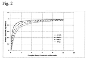
- the output electronic signal ratio which corresponds to the decay time intensity data collected by the bi-cell photodetector, will not only be impacted by the actual decay time of the active ion, but will also be affected by the distance between the first and second detector elements of the bi-cell photodetector and the constant velocity of the value document as it moves through the authentication apparatus as depicted in Fig. 2 .
- the electronic signal ratio is very close to 1, the ability to discriminate the decay times is poor unless the system averages the intensity data from the first and second detector elements from a number of consecutive images. The more consecutive images that are used for averaging will increase the ability of the authentication system to discriminate.
- the authentication apparatus may be designed to authenticate output electronic signal ratios in the range of 0.05 to 0.98 depending on the sensitivity and noise rejection of the detector, especially since the illumination from the exciting light source does not interfere with the detection of the emission from the active ion.
- the bi-cell photodetectors may have a circular geometry, the intensity data output by each of the first and second detector elements may be mathematically calculated by integrating across the exposed area of each detector element. One skilled in the art would be able to perform these calculations. Based on geometric considerations, the output electronic signal ratio would be expected to be different for a square bi-cell photodetector as compared to a circular bi-cell photodetector.
- the value document authentication apparatus of the present technology may determine pass data, thus validating, a value document if it calculates the measured output electronic signal ratio received from the first and second detector elements and determines that the measured output electronic signal ratio is within a pre-determined tolerance range of the at least one active ion of a known authentic covert composition.
- the pre-determined tolerance range can be selected based upon a reasonable amount of experimental error that may be introduced in performing authentication of the value document.
- a pre-determined tolerance range can be a one sigma standard deviation of up to about 2% of the ratio of the signals.
- the counterfeit document would be authenticated by any prior art validation system that only detects and validates based on a specific emission wavelength.
- the apparatus of the present technology would likely reject the counterfeit document as not having the decay characteristics of the pre-selected active ion because phosphors have compositional characteristic decay times as a function of host lattice, formation temperature, doping levels and the like. Additionally, if the output electronic signal ratio is not within the pre-determined tolerance range, the value document will be rejected as counterfeit.
- the pre-selected covert composition is uniformly incorporated into or onto the substrate of the value document. This may be achieved by uniformly mixing the pre-selected covert composition within the substrate paper pulp or by printing a uniform underlayer of the pre-selected covert composition uniformly mixed in an ink base onto the substrate of the value document. Due to the uniform distribution, the output electronic signal ratio measured between the second detector element electronic signal and the first detector element electronic signal of the bi-cell photodetector remains constant and reflects the decay characteristics of the pre-selected active ion when an unprinted/unsoiled location of the value document is imaged. A value document will be authenticated when the output electronic signal ratio falls within the pre-determined tolerance range. A number of consecutive images may be taken at each of the first and second detector elements. The corresponding consecutive output electronic signal ratios may be averaged to improve the accuracy of the system.
- the first detector element and second detector element of the bi-cell photodetector collect decay time intensity data in the form of electronic signals from adjacent but different portions of the moving value document when the image is captured. If these portions of the value document have different concentrations of the active ion, are covered by different levels of attenuating print, or if the emitting active ion is incorporated in the print ink and not in the value document substrate, then the output electronic signal ratio will account for both phosphor decay and the amount of phosphor excited as described in more detail below.
- a value document does not have a uniform distribution of a pre-selected covert composition such as when the covert composition is added to a printing ink with varying print density.
- a value document substrate with a uniform distribution of a pre-selected covert composition may be printed with an obscurant such as an absorbing ink thereby creating non-uniform distribution of phosphor emissions. This means that the first detector element may detect emission intensity from a different amount of available phosphors as compared to the second detector element.
- the document when the print pattern on the value document is varied and/or the amount of the pre-selected covert composition available is different from place to place on the value document, the document will be treated as having non-uniform distribution of the pre-selected covert composition.
- the output electronic signal ratio measured will be a combination of both decay behavior of the phosphor as well as the amount of phosphor present considering any attenuation of the emission signal due to the printing at each location.
- both the first detector element and second detector element will image the same area, or at least substantially the same area, of the moving value document over time.
- the first detector element can receive an image from an area of the value document at a first time
- the second detector element can receive an image of the same area, or substantially the same area, of the value document at a second time. This may be accomplished by separating the first and second image locations by an amount of time that allows the first detector element image to be coincident with the second detector element during a subsequent image reading.
- the phrase "coincidence time period" is defined as the amount of time required for the first detector element image to become approximately the same spatial image location detected at the second detector element at a later time. The coincidence time period may be selected to be the very next image whereby the first detector element first image location will be coincident with the first image location of the second detector element.
- the authentication system will be sufficiently accurate if each imaged section of the document that is measured by the first detector element is also approximately measured by the second detector element.
- the software within the authentication apparatus may be designed to select the appropriate coincidence images for calculating the average output electronic signal ratio to produce valid results for value document with non-uniform distribution of pre-selected covert composition.
- the processing unit of the present authentication apparatus can authenticate or reject a value document with a non-uniform distribution of a pre-selected covert composition despite any variable absorption of emission intensity by printed matter present on the value document, as it does not affect the measured output electronic signal ratio if averaged over a number of consecutive images taken from the value document.
- the corresponding calculated ratios may be averaged to improve the accuracy of the system.
- FIG. 1 illustrates a schematic diagram of the authentication apparatus 100 wherein a value document 101 is moved under an exciting light source window 102 and detection window 103.
- the exciting light comes from the phosphor exciting light source 104 and passes through the exciting light source window 102 to excite the active ion contained in or on the value document 101, within an illuminated area on the value document.
- the optical radiation from the active ion is roughly collimated by lens 105 and passed by an optical filter 106 to isolate the pre-selected emission wavelength of the active ion incorporated in the pre-selected covert composition.
- the pre-selected emission wavelength is then focused by lens 107 onto the bi-cell photodetector 108.
- the bi-cell photodetector 108 can be circular, having a first detector element 110A and a second detector element 110B, or can be rectangular or square, having a first detector element 112A and a second detector element 112B.
- the output electronic signal ratio relates to the decay characteristics of the active ion.
- the central processing unit (CPU) 109 can collect the output electronic signals from the first and second detector elements 110A and 110B or 112A and 112B at pre-determined intervals relating to pre-selected distances from the illuminated area on the value document, calculate the measured output electronic signal ratio, determine pass or failure data for the value document, and output the pass or failure data to indicate to an operator whether the value document is authentic.
- One way in which the CPU 109 can determine pass or failure data for the value document is to compare measured output electronic signal ratio to stored data corresponding to a known authentic covert composition.
- the CPU can also average the measured output electronic signal ratio from consecutive images to increase the accuracy of the measurement of the validation system.
- FIG. 2 illustrates the expected output electronic signal ratio of emitting phosphors having different characteristic decay times moving through the authentication apparatus at the indicated speeds as measured using a simulated 4-mm bi-cell photodetector with two semi-circular first and second detector elements assembled together with a split line that is perpendicular to the movement plane of the value document.
- Short life time ratios provide an output electronic signal ratio as low as 0.05
- long life time phosphors provide a ratio as high as 0.97, especially at high velocities of the value document.
- the bi-cell photodetector produces a highly accurate validation system, wherein it detects intensity data used to calculate the output electronic signal ratio in order to discriminate the pre-selected active ion in or on the value document.
- the present technology is not limited to bi-cell photodetectors.
- the first and second detector elements can be separated, and can be housed separately, which can improve accuracy.
- the bi-cell sensor element can be physically split into two separate sensors, or two separate sensors of the same type can otherwise be provided, placing a much larger separation between each photodetector element.
- a separate optical system can be provided to address the increased separation, but the method of signal sampling would remain the same.
- the data sampling rate can be synchronized such that the area sampled under the first detector element is also fully sampled under the second detector element at a later time, the same method as described for the bi-cell application.
- the requirements on the sensor elements and optical system remain the same as described above with respect to the bi-cell photodetector.
- the computations can also be the same, whereas the individual signal values are divided for the same spatial area of the note interrogated by taking the value from the second sensor element and dividing it by the value from the first sensor element.
- the sum of the signals of the second sensor can also be divided by the sum of the signals from the first sensor, for the length of the value document, to increase accuracy through statistical methodology.
- the decay time constant, Tau it is possible to maximize the accuracy of the decay time measurement in cases where the decay time constant, Tau, is long compared to the separation of the first and second detector elements combined with the transport speed of the value document. Higher degrees of accuracy can be obtained when the signal level has decayed to ⁇ 1/e value as measured at the second detector element and comparing that value to the same spatial area measured from the first detector element. If the value document speed is known, the detector element separation can be calculated for a pre-selected taggant. Preferably, the data sampling is an integral multiple of the chosen distance such that the same area is read by each detector element, but at a different time.
Landscapes
- Physics & Mathematics (AREA)
- Health & Medical Sciences (AREA)
- General Health & Medical Sciences (AREA)
- Toxicology (AREA)
- General Physics & Mathematics (AREA)
- Spectroscopy & Molecular Physics (AREA)
- Engineering & Computer Science (AREA)
- Multimedia (AREA)
- Theoretical Computer Science (AREA)
- Inspection Of Paper Currency And Valuable Securities (AREA)
- Editing Of Facsimile Originals (AREA)
- Investigating, Analyzing Materials By Fluorescence Or Luminescence (AREA)
- Image Input (AREA)
Claims (12)
- Appareil (100) qui authentifie un document de valeur (101) se déplaçant à une vitesse uniforme et qui comprend une composition secrète présélectionnée qui absorbe la lumière incidente d'excitation et émet un rayonnement optique ayant une longueur d'onde d'émission présélectionnée, l'appareil (100) comprenant :une source de lumière d'excitation (104) qui produit un éclairage d'une intensité suffisante pour exciter la composition secrète présélectionnée dans une zone éclairée par la source de lumière d'excitation (104) ;éventuellement un filtre optique (106) qui filtre la longueur d'onde d'émission présélectionnée émise par la composition secrète présélectionnée dans la zone éclairée ;un premier élément détecteur (110A) et un second élément détecteur (110B) situés dans au moins un photodétecteur (108), où le premier élément détecteur (110A) reçoit une première image d'une zone du document de valeur à un premier temps et délivre en sortie des données de signal électronique pour la première image, et le second élément détecteur (110B) reçoit une seconde image de sensiblement la même zone du document de valeur (101) à un second temps et délivre en sortie des données de signal électronique pour la seconde image, les première et seconde images correspondant à une intensité temporelle décroissante de la longueur d'onde d'émission présélectionnée émise par la composition secrète présélectionnée ;et une unité de traitement (109) qui collecte et évalue les données de signal électronique de sortie, et détermine des données de réussite ou d'échec pour le document de valeur (101).
- Appareil (100) tel que décrit dans la revendication 1, dans lequel le rayonnement optique a une constante de temps de décroissance située dans la plage s'étendant de 0,1 milliseconde à 10 millisecondes.
- Appareil (100) tel que décrit dans la revendication 1, dans lequel le photodétecteur (108) est un photodétecteur à deux cellules qui contient à la fois le premier élément détecteur (110A) et le second élément détecteur (110B), et la largeur du photodétecteur à deux cellules est d'environ 0,5 millimètre à environ 6 millimètres.
- Appareil (100) tel que décrit dans la revendication 1, dans lequel la première image et la seconde image sont décalées d'une distance qui représente un temps qui est compris entre 0,5 et 2 constantes de temps de décroissance de l'émission du rayonnement optique lorsque le document de valeur est déplacé à la vitesse uniforme.
- Appareil (100) tel que décrit dans la revendication 1, dans lequel la vitesse uniforme du document de valeur se déplaçant se situe dans la plage s'étendant de 1 à 12 m/s.
- Appareil (100) tel que décrit dans la revendication 1, dans lequel l'unité de traitement (109) détermine les données de réussite ou d'échec pour le document de valeur (101) en comparant le rapport du signal électronique de sortie mesuré aux données stockées correspondant à une composition secrète authentique connue.
- Appareil (100) tel que décrit dans la revendication 1, dans lequel le document de valeur (101) est un billet de banque.
- Appareil (100) tel que décrit dans la revendication 1, dans lequel la source de lumière d'excitation (104) fournit un éclairage infrarouge.
- Appareil (100) tel que décrit dans la revendication 1, dans lequel la longueur d'onde d'émission présélectionnée se situe dans le spectre infrarouge.
- Procédé d'authentification d'un document de valeur (101) comprenant d'une composition secrète présélectionnée qui absorbe la lumière incidente d'excitation et émet un rayonnement optique, comprenant les étapes suivantes :déplacer le document de valeur (101) à une vitesse uniforme devant une zone éclairée produite par une source de lumière d'excitation (104) qui produit un éclairage ayant une intensité suffisante pour exciter la composition secrète présélectionnée ;éventuellement filtrer une longueur d'onde d'émission présélectionnée issue de la composition secrète présélectionnée dans la zone éclairée lorsque le document de valeur (101) passe une fenêtre de détection avec un filtre optique (106) ;fournir une première image d'une zone du document de valeur (101) à un premier élément détecteur (110A) situé dans au moins un photodétecteur (108) à un premier temps ;fournir une seconde image de sensiblement la même zone du document de valeur (101) à un second élément détecteur (110B) situé dans l'au moins un photodétecteur (108) à un second temps ;délivrer en sortie des données de signal électronique pour les première et seconde images à partir de l'au moins un photodétecteur (108),collecter les données de signal électronique de sortie dans une unité de traitement (109) ; etdéterminer des données de réussite ou d'échec pour le document de valeur (101).
- Procédé selon la revendication 10, dans lequel le document de valeur (101) est un billet de banque.
- Procédé selon la revendication 10, comprenant en outre de fournir une série de première et seconde images consécutives, et de moyenner les rapports de signal électronique délivrés en sortie issus de ladite série d'images consécutives dans ladite unité de traitement (109).
Applications Claiming Priority (3)
| Application Number | Priority Date | Filing Date | Title |
|---|---|---|---|
| US26362409P | 2009-11-23 | 2009-11-23 | |
| US12/950,390 US8263948B2 (en) | 2009-11-23 | 2010-11-19 | Authentication apparatus for moving value documents |
| PCT/US2010/057564 WO2011063317A2 (fr) | 2009-11-23 | 2010-11-22 | Appareil d'authentification pour documents de valeur en mouvement |
Publications (3)
| Publication Number | Publication Date |
|---|---|
| EP2504819A2 EP2504819A2 (fr) | 2012-10-03 |
| EP2504819A4 EP2504819A4 (fr) | 2013-09-18 |
| EP2504819B1 true EP2504819B1 (fr) | 2016-06-29 |
Family
ID=44060384
Family Applications (1)
| Application Number | Title | Priority Date | Filing Date |
|---|---|---|---|
| EP10832310.6A Revoked EP2504819B1 (fr) | 2009-11-23 | 2010-11-22 | Appareil d'authentification pour documents de valeur en mouvement |
Country Status (7)
| Country | Link |
|---|---|
| US (1) | US8263948B2 (fr) |
| EP (1) | EP2504819B1 (fr) |
| JP (1) | JP5675837B2 (fr) |
| KR (1) | KR101818000B1 (fr) |
| CN (1) | CN102754129B (fr) |
| ES (1) | ES2592279T3 (fr) |
| WO (1) | WO2011063317A2 (fr) |
Families Citing this family (13)
| Publication number | Priority date | Publication date | Assignee | Title |
|---|---|---|---|---|
| US8791428B2 (en) * | 2009-10-14 | 2014-07-29 | Honeywell International Inc. | Authentication systems for discriminating value documents based on variable luminescence and magnetic properties |
| DE102010047948A1 (de) * | 2010-10-08 | 2012-04-12 | Giesecke & Devrient Gmbh | Verfahren zum Prüfen eines optischen Sicherheitsmerkmals eines Wertdokuments |
| JP2014519130A (ja) * | 2011-06-06 | 2014-08-07 | シクパ ホルディング ソシエテ アノニム | インライン減衰時間スキャナ |
| US20130048874A1 (en) * | 2011-08-31 | 2013-02-28 | Honeywell International Inc. | Articles with confounded emission characteristics and methods and apparatus for their authentication |
| DE102011114410A1 (de) * | 2011-09-26 | 2013-03-28 | Giesecke & Devrient Gmbh | Verfahren zum Prüfen der Herstellungsqualität eines optischen Sicherheitsmerkmals eines Wertdokuments |
| US8759794B2 (en) * | 2012-07-20 | 2014-06-24 | Honeywell International Inc. | Articles, methods of validating the same, and validation systems employing decay constant modulation |
| US9053596B2 (en) * | 2012-07-31 | 2015-06-09 | De La Rue North America Inc. | Systems and methods for spectral authentication of a feature of a document |
| CN104469070A (zh) * | 2014-12-24 | 2015-03-25 | 威海华菱光电股份有限公司 | 接触式图像传感器和包括其的图像扫描装置 |
| CN108022361B (zh) * | 2016-10-31 | 2021-05-28 | 威海新北洋荣鑫科技股份有限公司 | 图像数据获取方法及装置 |
| FR3069353B1 (fr) * | 2017-07-21 | 2020-07-17 | Jean-Jacques Florent | Methode d'authentification par voie optique et identificateur associe |
| JP7111494B2 (ja) * | 2018-04-05 | 2022-08-02 | グローリー株式会社 | 光検出センサ、光検出装置、シート類処理装置および光検出方法 |
| CN110110566B (zh) * | 2019-05-15 | 2022-09-16 | 中钞印制技术研究院有限公司 | 移动设备及其物品鉴别方法和装置、计算机可读存储介质 |
| DE102020004471A1 (de) | 2020-07-23 | 2022-01-27 | Giesecke+Devrient Currency Technology Gmbh | Verfahren und Sensor zur Prüfung von Wertdokumenten |
Citations (19)
| Publication number | Priority date | Publication date | Assignee | Title |
|---|---|---|---|---|
| DE1524711A1 (de) | 1966-02-09 | 1970-07-09 | American Cyanamid Co | Verfahren und Vorrichtung zum Aufzeichnen und Lesen von Daten |
| WO1981003509A1 (fr) | 1980-05-30 | 1981-12-10 | Gao Ges Automation Org | Papier-valeur avec marque d'authenticite en matiere luminescente et procede pour son authentification |
| WO1981003508A1 (fr) | 1980-05-30 | 1981-12-10 | Gao Ges Automation Org | Papier-valeur avec marque d'authenticite en matiere luminescente et procede pour son utilisation |
| GB2095822A (en) | 1981-03-30 | 1982-10-06 | Ramley Engineering Co Ltd | Identifying objects by detecting decaying phosphorescence from phosphor coating thereon |
| US4592090A (en) | 1981-08-11 | 1986-05-27 | De La Rue Systems Limited | Apparatus for scanning a sheet |
| US5459323A (en) | 1990-01-12 | 1995-10-17 | University Of Salford | Measurement of luminescence |
| US5679959A (en) | 1995-01-11 | 1997-10-21 | Laurel Bank Machines Co., Ltd. | Bill discriminating apparatus |
| WO1999038703A1 (fr) | 1998-02-02 | 1999-08-05 | Giesecke & Devrient Gmbh | Document de valeur imprime comportant une caracteristique d'authenticite luminescente |
| WO1999038702A1 (fr) | 1998-02-02 | 1999-08-05 | Giesecke & Devrient Gmbh | Document de valeur imprime comportant une caracteristique d'authenticite luminescente |
| EP1158459A1 (fr) | 2000-05-16 | 2001-11-28 | Sicpa Holding S.A. | Méthode, dispositif et système pour authentifier un marquage |
| EP1244073A2 (fr) | 2001-03-16 | 2002-09-25 | BUNDESDRUCKEREI GmbH | Méthode et palpeur pour la validation de documents |
| DE10127836A1 (de) | 2001-06-08 | 2003-01-30 | Giesecke & Devrient Gmbh | Vorrichtung zur Untersuchung von Dokumenten |
| WO2003105075A1 (fr) | 2002-06-07 | 2003-12-18 | Trustees Of Boston University | Systeme et procedes d'authentification de produits et documents |
| DE102004016249A1 (de) | 2004-04-02 | 2005-10-20 | Chromeon Gmbh | Lumineszenz-optische Verfahren zur Authentikation von Produkten |
| US7030371B2 (en) | 2001-03-01 | 2006-04-18 | Sicpa Holding S.A. | Luminescence characteristics detector |
| US7274027B2 (en) | 2004-03-18 | 2007-09-25 | Optometrix Inc. | Scanning systems and methods with time delay sensing |
| US20090152468A1 (en) | 2005-12-16 | 2009-06-18 | Filtrona Plc | Detection apparatus and method |
| DE102009006112A1 (de) | 2008-02-01 | 2009-08-06 | Austrian Research Centers Gmbh - Arc | Verfahren und Vorrichtung zum Prüfen von Lumineszenzfarbmuster tragenden Gegenständen |
| DE102010046328A1 (de) | 2010-09-23 | 2012-03-29 | Giesecke & Devrient Gmbh | Vorrichtung für die Bearbeitung von Blattgut |
Family Cites Families (19)
| Publication number | Priority date | Publication date | Assignee | Title |
|---|---|---|---|---|
| DE3116257A1 (de) * | 1980-05-30 | 1982-01-07 | GAO Gesellschaft für Automation und Organisation mbH, 8000 München | "wertpapier mit echtheitsmerkmalen" |
| US6155491A (en) * | 1998-05-29 | 2000-12-05 | Welch Allyn Data Collection, Inc. | Lottery game ticket processing apparatus |
| US6473165B1 (en) * | 2000-01-21 | 2002-10-29 | Flex Products, Inc. | Automated verification systems and methods for use with optical interference devices |
| DE10127837A1 (de) * | 2001-06-08 | 2003-01-23 | Giesecke & Devrient Gmbh | Vorrichtung und Verfahren zur Untersuchung von Dokumenten |
| US7222712B2 (en) * | 2003-03-24 | 2007-05-29 | Valtech International, Llc | Document validator with locking cassette |
| EP1473657A1 (fr) * | 2003-04-29 | 2004-11-03 | Sicpa Holding S.A. | Méthode et dispositif pour l'authentification de documents et de marchandises |
| US6914668B2 (en) * | 2003-05-14 | 2005-07-05 | International Technologies (Laser) Ltd. | Personal identification verification and controlled substance detection and identification system |
| JP4334910B2 (ja) * | 2003-05-28 | 2009-09-30 | ローレル精機株式会社 | 紙幣画像検出装置 |
| DE10346634A1 (de) * | 2003-10-08 | 2005-05-12 | Giesecke & Devrient Gmbh | Wertdokument |
| CA2559100C (fr) * | 2004-03-08 | 2013-04-23 | Council Of Scientific And Industrial Research | Detecteur ameliore de fausse monnaie mettant en oeuvre une reponse integree de transmission et spectrale reflechissante |
| US20060017959A1 (en) * | 2004-07-06 | 2006-01-26 | Downer Raymond J | Document classification and authentication |
| JP2006065771A (ja) * | 2004-08-30 | 2006-03-09 | Toshiba Corp | 判別装置 |
| JP2006266810A (ja) * | 2005-03-23 | 2006-10-05 | National Printing Bureau | 真偽判別装置及び真偽判別方法 |
| JP4901228B2 (ja) * | 2006-02-07 | 2012-03-21 | 株式会社東芝 | 分光検出装置 |
| JP2008055639A (ja) | 2006-08-29 | 2008-03-13 | National Printing Bureau | 真偽判別印刷物及び真偽判別方法 |
| JP2008197850A (ja) | 2007-02-09 | 2008-08-28 | Internatl Currency Technologies Corp | 有価証券識別装置 |
| US8257612B2 (en) | 2007-07-05 | 2012-09-04 | Cabot Corporation | Compositions having multiple responses to excitation radiation and methods for making same |
| JP5526366B2 (ja) | 2008-03-17 | 2014-06-18 | 株式会社ユニバーサルエンターテインメント | 偽造識別装置、及び、偽造識別方法 |
| US8749767B2 (en) * | 2009-09-02 | 2014-06-10 | De La Rue North America Inc. | Systems and methods for detecting tape on a document |
-
2010
- 2010-11-19 US US12/950,390 patent/US8263948B2/en active Active
- 2010-11-22 EP EP10832310.6A patent/EP2504819B1/fr not_active Revoked
- 2010-11-22 CN CN201080052955.1A patent/CN102754129B/zh not_active Expired - Fee Related
- 2010-11-22 ES ES10832310.6T patent/ES2592279T3/es active Active
- 2010-11-22 KR KR1020127016309A patent/KR101818000B1/ko active Active
- 2010-11-22 JP JP2012540124A patent/JP5675837B2/ja not_active Expired - Fee Related
- 2010-11-22 WO PCT/US2010/057564 patent/WO2011063317A2/fr not_active Ceased
Patent Citations (19)
| Publication number | Priority date | Publication date | Assignee | Title |
|---|---|---|---|---|
| DE1524711A1 (de) | 1966-02-09 | 1970-07-09 | American Cyanamid Co | Verfahren und Vorrichtung zum Aufzeichnen und Lesen von Daten |
| WO1981003509A1 (fr) | 1980-05-30 | 1981-12-10 | Gao Ges Automation Org | Papier-valeur avec marque d'authenticite en matiere luminescente et procede pour son authentification |
| WO1981003508A1 (fr) | 1980-05-30 | 1981-12-10 | Gao Ges Automation Org | Papier-valeur avec marque d'authenticite en matiere luminescente et procede pour son utilisation |
| GB2095822A (en) | 1981-03-30 | 1982-10-06 | Ramley Engineering Co Ltd | Identifying objects by detecting decaying phosphorescence from phosphor coating thereon |
| US4592090A (en) | 1981-08-11 | 1986-05-27 | De La Rue Systems Limited | Apparatus for scanning a sheet |
| US5459323A (en) | 1990-01-12 | 1995-10-17 | University Of Salford | Measurement of luminescence |
| US5679959A (en) | 1995-01-11 | 1997-10-21 | Laurel Bank Machines Co., Ltd. | Bill discriminating apparatus |
| WO1999038702A1 (fr) | 1998-02-02 | 1999-08-05 | Giesecke & Devrient Gmbh | Document de valeur imprime comportant une caracteristique d'authenticite luminescente |
| WO1999038703A1 (fr) | 1998-02-02 | 1999-08-05 | Giesecke & Devrient Gmbh | Document de valeur imprime comportant une caracteristique d'authenticite luminescente |
| EP1158459A1 (fr) | 2000-05-16 | 2001-11-28 | Sicpa Holding S.A. | Méthode, dispositif et système pour authentifier un marquage |
| US7030371B2 (en) | 2001-03-01 | 2006-04-18 | Sicpa Holding S.A. | Luminescence characteristics detector |
| EP1244073A2 (fr) | 2001-03-16 | 2002-09-25 | BUNDESDRUCKEREI GmbH | Méthode et palpeur pour la validation de documents |
| DE10127836A1 (de) | 2001-06-08 | 2003-01-30 | Giesecke & Devrient Gmbh | Vorrichtung zur Untersuchung von Dokumenten |
| WO2003105075A1 (fr) | 2002-06-07 | 2003-12-18 | Trustees Of Boston University | Systeme et procedes d'authentification de produits et documents |
| US7274027B2 (en) | 2004-03-18 | 2007-09-25 | Optometrix Inc. | Scanning systems and methods with time delay sensing |
| DE102004016249A1 (de) | 2004-04-02 | 2005-10-20 | Chromeon Gmbh | Lumineszenz-optische Verfahren zur Authentikation von Produkten |
| US20090152468A1 (en) | 2005-12-16 | 2009-06-18 | Filtrona Plc | Detection apparatus and method |
| DE102009006112A1 (de) | 2008-02-01 | 2009-08-06 | Austrian Research Centers Gmbh - Arc | Verfahren und Vorrichtung zum Prüfen von Lumineszenzfarbmuster tragenden Gegenständen |
| DE102010046328A1 (de) | 2010-09-23 | 2012-03-29 | Giesecke & Devrient Gmbh | Vorrichtung für die Bearbeitung von Blattgut |
Also Published As
| Publication number | Publication date |
|---|---|
| WO2011063317A3 (fr) | 2011-11-24 |
| US8263948B2 (en) | 2012-09-11 |
| CN102754129A (zh) | 2012-10-24 |
| KR101818000B1 (ko) | 2018-01-12 |
| EP2504819A2 (fr) | 2012-10-03 |
| JP2013511926A (ja) | 2013-04-04 |
| ES2592279T3 (es) | 2016-11-29 |
| WO2011063317A2 (fr) | 2011-05-26 |
| KR20120105483A (ko) | 2012-09-25 |
| CN102754129B (zh) | 2015-05-20 |
| EP2504819A4 (fr) | 2013-09-18 |
| US20110121203A1 (en) | 2011-05-26 |
| JP5675837B2 (ja) | 2015-02-25 |
Similar Documents
| Publication | Publication Date | Title |
|---|---|---|
| EP2504819B1 (fr) | Appareil d'authentification pour documents de valeur en mouvement | |
| CN102598023B (zh) | 用于价值票据的鉴别设备 | |
| US7092583B2 (en) | Apparatus and method for detecting the authenticity of secured documents | |
| EP3213303B1 (fr) | Systèmes d'authentification, dispositifs d'authentification, et procédés pour authentifier un article de valeur | |
| JPH08185558A (ja) | 書類を認証する方法および装置 | |
| CN101263012B (zh) | 有价证券及其制造和检验 | |
| KR20140056273A (ko) | 발광성 인광체 화합물로 물품을 인증하기 위한 방법과 장치 | |
| US9031307B2 (en) | Apparatus and method for checking documents of value | |
| WO2012094896A1 (fr) | Procédé et dispositif d'identification de billets de banque ou d'autres billets financiers | |
| EP2549445A1 (fr) | Unité et procédé de distinction authentique/contrefaçon et capteur de fluorescence | |
| US8212205B2 (en) | Device and method for verifying valuable documents | |
| US7403272B1 (en) | Method and device for the detection of counterfeit documents and banknotes | |
| KR100945268B1 (ko) | 위조지폐 감별유니트 | |
| RU2115169C1 (ru) | Способ определения подлинности банкноты | |
| US12387546B2 (en) | Method and device for testing a substrate with a luminescent substance | |
| RU185984U1 (ru) | Портативное устройство для полуавтоматической проверки наличия на банкнотах защитных антистоксовых меток (спецэлемент и) | |
| HK1178301B (en) | Sensor for verifying value documents | |
| HK1178301A (en) | Sensor for verifying value documents |
Legal Events
| Date | Code | Title | Description |
|---|---|---|---|
| PUAI | Public reference made under article 153(3) epc to a published international application that has entered the european phase |
Free format text: ORIGINAL CODE: 0009012 |
|
| 17P | Request for examination filed |
Effective date: 20120508 |
|
| AK | Designated contracting states |
Kind code of ref document: A2 Designated state(s): AL AT BE BG CH CY CZ DE DK EE ES FI FR GB GR HR HU IE IS IT LI LT LU LV MC MK MT NL NO PL PT RO RS SE SI SK SM TR |
|
| DAX | Request for extension of the european patent (deleted) | ||
| A4 | Supplementary search report drawn up and despatched |
Effective date: 20130816 |
|
| RIC1 | Information provided on ipc code assigned before grant |
Ipc: G06K 9/28 20060101ALI20130809BHEP Ipc: G07D 7/12 20060101AFI20130809BHEP Ipc: G06K 9/58 20060101ALI20130809BHEP |
|
| 17Q | First examination report despatched |
Effective date: 20130917 |
|
| RAP1 | Party data changed (applicant data changed or rights of an application transferred) |
Owner name: HONEYWELL INTERNATIONAL INC. |
|
| GRAP | Despatch of communication of intention to grant a patent |
Free format text: ORIGINAL CODE: EPIDOSNIGR1 |
|
| INTG | Intention to grant announced |
Effective date: 20160215 |
|
| RIN1 | Information on inventor provided before grant (corrected) |
Inventor name: RAPOPORT, WILLIAM, ROSS Inventor name: KANE, JAMES Inventor name: LAU, CARSTEN |
|
| GRAS | Grant fee paid |
Free format text: ORIGINAL CODE: EPIDOSNIGR3 |
|
| GRAA | (expected) grant |
Free format text: ORIGINAL CODE: 0009210 |
|
| AK | Designated contracting states |
Kind code of ref document: B1 Designated state(s): AL AT BE BG CH CY CZ DE DK EE ES FI FR GB GR HR HU IE IS IT LI LT LU LV MC MK MT NL NO PL PT RO RS SE SI SK SM TR |
|
| REG | Reference to a national code |
Ref country code: GB Ref legal event code: FG4D |
|
| REG | Reference to a national code |
Ref country code: CH Ref legal event code: EP |
|
| REG | Reference to a national code |
Ref country code: AT Ref legal event code: REF Ref document number: 809634 Country of ref document: AT Kind code of ref document: T Effective date: 20160715 |
|
| REG | Reference to a national code |
Ref country code: IE Ref legal event code: FG4D |
|
| REG | Reference to a national code |
Ref country code: DE Ref legal event code: R096 Ref document number: 602010034394 Country of ref document: DE |
|
| REG | Reference to a national code |
Ref country code: FR Ref legal event code: PLFP Year of fee payment: 7 |
|
| REG | Reference to a national code |
Ref country code: LT Ref legal event code: MG4D |
|
| PG25 | Lapsed in a contracting state [announced via postgrant information from national office to epo] |
Ref country code: FI Free format text: LAPSE BECAUSE OF FAILURE TO SUBMIT A TRANSLATION OF THE DESCRIPTION OR TO PAY THE FEE WITHIN THE PRESCRIBED TIME-LIMIT Effective date: 20160629 Ref country code: LT Free format text: LAPSE BECAUSE OF FAILURE TO SUBMIT A TRANSLATION OF THE DESCRIPTION OR TO PAY THE FEE WITHIN THE PRESCRIBED TIME-LIMIT Effective date: 20160629 Ref country code: NO Free format text: LAPSE BECAUSE OF FAILURE TO SUBMIT A TRANSLATION OF THE DESCRIPTION OR TO PAY THE FEE WITHIN THE PRESCRIBED TIME-LIMIT Effective date: 20160929 |
|
| REG | Reference to a national code |
Ref country code: NL Ref legal event code: MP Effective date: 20160629 |
|
| REG | Reference to a national code |
Ref country code: ES Ref legal event code: FG2A Ref document number: 2592279 Country of ref document: ES Kind code of ref document: T3 Effective date: 20161129 |
|
| PG25 | Lapsed in a contracting state [announced via postgrant information from national office to epo] |
Ref country code: GR Free format text: LAPSE BECAUSE OF FAILURE TO SUBMIT A TRANSLATION OF THE DESCRIPTION OR TO PAY THE FEE WITHIN THE PRESCRIBED TIME-LIMIT Effective date: 20160930 Ref country code: RS Free format text: LAPSE BECAUSE OF FAILURE TO SUBMIT A TRANSLATION OF THE DESCRIPTION OR TO PAY THE FEE WITHIN THE PRESCRIBED TIME-LIMIT Effective date: 20160629 Ref country code: SE Free format text: LAPSE BECAUSE OF FAILURE TO SUBMIT A TRANSLATION OF THE DESCRIPTION OR TO PAY THE FEE WITHIN THE PRESCRIBED TIME-LIMIT Effective date: 20160629 Ref country code: NL Free format text: LAPSE BECAUSE OF FAILURE TO SUBMIT A TRANSLATION OF THE DESCRIPTION OR TO PAY THE FEE WITHIN THE PRESCRIBED TIME-LIMIT Effective date: 20160629 Ref country code: LV Free format text: LAPSE BECAUSE OF FAILURE TO SUBMIT A TRANSLATION OF THE DESCRIPTION OR TO PAY THE FEE WITHIN THE PRESCRIBED TIME-LIMIT Effective date: 20160629 Ref country code: HR Free format text: LAPSE BECAUSE OF FAILURE TO SUBMIT A TRANSLATION OF THE DESCRIPTION OR TO PAY THE FEE WITHIN THE PRESCRIBED TIME-LIMIT Effective date: 20160629 |
|
| REG | Reference to a national code |
Ref country code: AT Ref legal event code: MK05 Ref document number: 809634 Country of ref document: AT Kind code of ref document: T Effective date: 20160629 |
|
| PG25 | Lapsed in a contracting state [announced via postgrant information from national office to epo] |
Ref country code: CZ Free format text: LAPSE BECAUSE OF FAILURE TO SUBMIT A TRANSLATION OF THE DESCRIPTION OR TO PAY THE FEE WITHIN THE PRESCRIBED TIME-LIMIT Effective date: 20160629 Ref country code: RO Free format text: LAPSE BECAUSE OF FAILURE TO SUBMIT A TRANSLATION OF THE DESCRIPTION OR TO PAY THE FEE WITHIN THE PRESCRIBED TIME-LIMIT Effective date: 20160629 Ref country code: IS Free format text: LAPSE BECAUSE OF FAILURE TO SUBMIT A TRANSLATION OF THE DESCRIPTION OR TO PAY THE FEE WITHIN THE PRESCRIBED TIME-LIMIT Effective date: 20161029 Ref country code: SK Free format text: LAPSE BECAUSE OF FAILURE TO SUBMIT A TRANSLATION OF THE DESCRIPTION OR TO PAY THE FEE WITHIN THE PRESCRIBED TIME-LIMIT Effective date: 20160629 Ref country code: EE Free format text: LAPSE BECAUSE OF FAILURE TO SUBMIT A TRANSLATION OF THE DESCRIPTION OR TO PAY THE FEE WITHIN THE PRESCRIBED TIME-LIMIT Effective date: 20160629 |
|
| PG25 | Lapsed in a contracting state [announced via postgrant information from national office to epo] |
Ref country code: AT Free format text: LAPSE BECAUSE OF FAILURE TO SUBMIT A TRANSLATION OF THE DESCRIPTION OR TO PAY THE FEE WITHIN THE PRESCRIBED TIME-LIMIT Effective date: 20160629 Ref country code: PT Free format text: LAPSE BECAUSE OF FAILURE TO SUBMIT A TRANSLATION OF THE DESCRIPTION OR TO PAY THE FEE WITHIN THE PRESCRIBED TIME-LIMIT Effective date: 20161031 Ref country code: PL Free format text: LAPSE BECAUSE OF FAILURE TO SUBMIT A TRANSLATION OF THE DESCRIPTION OR TO PAY THE FEE WITHIN THE PRESCRIBED TIME-LIMIT Effective date: 20160629 Ref country code: BE Free format text: LAPSE BECAUSE OF FAILURE TO SUBMIT A TRANSLATION OF THE DESCRIPTION OR TO PAY THE FEE WITHIN THE PRESCRIBED TIME-LIMIT Effective date: 20160629 Ref country code: SM Free format text: LAPSE BECAUSE OF FAILURE TO SUBMIT A TRANSLATION OF THE DESCRIPTION OR TO PAY THE FEE WITHIN THE PRESCRIBED TIME-LIMIT Effective date: 20160629 |
|
| REG | Reference to a national code |
Ref country code: DE Ref legal event code: R026 Ref document number: 602010034394 Country of ref document: DE |
|
| PLBI | Opposition filed |
Free format text: ORIGINAL CODE: 0009260 |
|
| 26 | Opposition filed |
Opponent name: GIESECKE & DEVRIENT GMBH Effective date: 20170320 |
|
| PLAX | Notice of opposition and request to file observation + time limit sent |
Free format text: ORIGINAL CODE: EPIDOSNOBS2 |
|
| PG25 | Lapsed in a contracting state [announced via postgrant information from national office to epo] |
Ref country code: DK Free format text: LAPSE BECAUSE OF FAILURE TO SUBMIT A TRANSLATION OF THE DESCRIPTION OR TO PAY THE FEE WITHIN THE PRESCRIBED TIME-LIMIT Effective date: 20160629 |
|
| REG | Reference to a national code |
Ref country code: IE Ref legal event code: MM4A |
|
| PG25 | Lapsed in a contracting state [announced via postgrant information from national office to epo] |
Ref country code: BG Free format text: LAPSE BECAUSE OF FAILURE TO SUBMIT A TRANSLATION OF THE DESCRIPTION OR TO PAY THE FEE WITHIN THE PRESCRIBED TIME-LIMIT Effective date: 20160929 Ref country code: SI Free format text: LAPSE BECAUSE OF FAILURE TO SUBMIT A TRANSLATION OF THE DESCRIPTION OR TO PAY THE FEE WITHIN THE PRESCRIBED TIME-LIMIT Effective date: 20160629 |
|
| PLBB | Reply of patent proprietor to notice(s) of opposition received |
Free format text: ORIGINAL CODE: EPIDOSNOBS3 |
|
| PG25 | Lapsed in a contracting state [announced via postgrant information from national office to epo] |
Ref country code: LU Free format text: LAPSE BECAUSE OF NON-PAYMENT OF DUE FEES Effective date: 20161130 |
|
| REG | Reference to a national code |
Ref country code: FR Ref legal event code: PLFP Year of fee payment: 8 |
|
| PG25 | Lapsed in a contracting state [announced via postgrant information from national office to epo] |
Ref country code: IE Free format text: LAPSE BECAUSE OF NON-PAYMENT OF DUE FEES Effective date: 20161122 |
|
| PLAB | Opposition data, opponent's data or that of the opponent's representative modified |
Free format text: ORIGINAL CODE: 0009299OPPO |
|
| R26 | Opposition filed (corrected) |
Opponent name: GIESECKE+DEVRIENT CURRENCY TECHNOLOGY GMBH Effective date: 20170320 |
|
| PG25 | Lapsed in a contracting state [announced via postgrant information from national office to epo] |
Ref country code: CY Free format text: LAPSE BECAUSE OF FAILURE TO SUBMIT A TRANSLATION OF THE DESCRIPTION OR TO PAY THE FEE WITHIN THE PRESCRIBED TIME-LIMIT Effective date: 20160629 Ref country code: HU Free format text: LAPSE BECAUSE OF FAILURE TO SUBMIT A TRANSLATION OF THE DESCRIPTION OR TO PAY THE FEE WITHIN THE PRESCRIBED TIME-LIMIT; INVALID AB INITIO Effective date: 20101122 |
|
| PG25 | Lapsed in a contracting state [announced via postgrant information from national office to epo] |
Ref country code: MC Free format text: LAPSE BECAUSE OF FAILURE TO SUBMIT A TRANSLATION OF THE DESCRIPTION OR TO PAY THE FEE WITHIN THE PRESCRIBED TIME-LIMIT Effective date: 20160629 Ref country code: TR Free format text: LAPSE BECAUSE OF FAILURE TO SUBMIT A TRANSLATION OF THE DESCRIPTION OR TO PAY THE FEE WITHIN THE PRESCRIBED TIME-LIMIT Effective date: 20160629 Ref country code: MK Free format text: LAPSE BECAUSE OF FAILURE TO SUBMIT A TRANSLATION OF THE DESCRIPTION OR TO PAY THE FEE WITHIN THE PRESCRIBED TIME-LIMIT Effective date: 20160629 |
|
| PG25 | Lapsed in a contracting state [announced via postgrant information from national office to epo] |
Ref country code: MT Free format text: LAPSE BECAUSE OF NON-PAYMENT OF DUE FEES Effective date: 20161122 |
|
| PG25 | Lapsed in a contracting state [announced via postgrant information from national office to epo] |
Ref country code: AL Free format text: LAPSE BECAUSE OF FAILURE TO SUBMIT A TRANSLATION OF THE DESCRIPTION OR TO PAY THE FEE WITHIN THE PRESCRIBED TIME-LIMIT Effective date: 20160629 |
|
| RDAF | Communication despatched that patent is revoked |
Free format text: ORIGINAL CODE: EPIDOSNREV1 |
|
| STAA | Information on the status of an ep patent application or granted ep patent |
Free format text: STATUS: THE PATENT HAS BEEN GRANTED |
|
| APBM | Appeal reference recorded |
Free format text: ORIGINAL CODE: EPIDOSNREFNO |
|
| APBP | Date of receipt of notice of appeal recorded |
Free format text: ORIGINAL CODE: EPIDOSNNOA2O |
|
| APAH | Appeal reference modified |
Free format text: ORIGINAL CODE: EPIDOSCREFNO |
|
| PGFP | Annual fee paid to national office [announced via postgrant information from national office to epo] |
Ref country code: BE Payment date: 20181019 Year of fee payment: 7 |
|
| APBQ | Date of receipt of statement of grounds of appeal recorded |
Free format text: ORIGINAL CODE: EPIDOSNNOA3O |
|
| REG | Reference to a national code |
Ref country code: CH Ref legal event code: PL |
|
| PG25 | Lapsed in a contracting state [announced via postgrant information from national office to epo] |
Ref country code: CH Free format text: LAPSE BECAUSE OF NON-PAYMENT OF DUE FEES Effective date: 20191130 Ref country code: LI Free format text: LAPSE BECAUSE OF NON-PAYMENT OF DUE FEES Effective date: 20191130 |
|
| PGFP | Annual fee paid to national office [announced via postgrant information from national office to epo] |
Ref country code: DE Payment date: 20201130 Year of fee payment: 11 |
|
| REG | Reference to a national code |
Ref country code: DE Ref legal event code: R103 Ref document number: 602010034394 Country of ref document: DE Ref country code: DE Ref legal event code: R064 Ref document number: 602010034394 Country of ref document: DE |
|
| APBU | Appeal procedure closed |
Free format text: ORIGINAL CODE: EPIDOSNNOA9O |
|
| RDAG | Patent revoked |
Free format text: ORIGINAL CODE: 0009271 |
|
| STAA | Information on the status of an ep patent application or granted ep patent |
Free format text: STATUS: PATENT REVOKED |
|
| REG | Reference to a national code |
Ref country code: CH Ref legal event code: PL |
|
| REG | Reference to a national code |
Ref country code: FI Ref legal event code: MGE |
|
| 27W | Patent revoked |
Effective date: 20211125 |
|
| GBPR | Gb: patent revoked under art. 102 of the ep convention designating the uk as contracting state |
Effective date: 20211125 |
|
| PGFP | Annual fee paid to national office [announced via postgrant information from national office to epo] |
Ref country code: GB Payment date: 20211123 Year of fee payment: 12 Ref country code: ES Payment date: 20211216 Year of fee payment: 12 Ref country code: FR Payment date: 20211126 Year of fee payment: 12 |
|
| PLAB | Opposition data, opponent's data or that of the opponent's representative modified |
Free format text: ORIGINAL CODE: 0009299OPPO |
|
| PGFP | Annual fee paid to national office [announced via postgrant information from national office to epo] |
Ref country code: IT Payment date: 20211119 Year of fee payment: 12 |
|
| R26 | Opposition filed (corrected) |
Opponent name: GIESECKE+DEVRIENT CURRENCY TECHNOLOGY GMBH Effective date: 20170320 |