EP1244105A2 - Gerät zur Wiedergabe von aufgezeichneten Daten - Google Patents
Gerät zur Wiedergabe von aufgezeichneten Daten Download PDFInfo
- Publication number
- EP1244105A2 EP1244105A2 EP01127673A EP01127673A EP1244105A2 EP 1244105 A2 EP1244105 A2 EP 1244105A2 EP 01127673 A EP01127673 A EP 01127673A EP 01127673 A EP01127673 A EP 01127673A EP 1244105 A2 EP1244105 A2 EP 1244105A2
- Authority
- EP
- European Patent Office
- Prior art keywords
- crosstalk
- signal
- data
- track
- reproduction
- Prior art date
- Legal status (The legal status is an assumption and is not a legal conclusion. Google has not performed a legal analysis and makes no representation as to the accuracy of the status listed.)
- Granted
Links
Images









Classifications
-
- G—PHYSICS
- G11—INFORMATION STORAGE
- G11B—INFORMATION STORAGE BASED ON RELATIVE MOVEMENT BETWEEN RECORD CARRIER AND TRANSDUCER
- G11B20/00—Signal processing not specific to the method of recording or reproducing; Circuits therefor
- G11B20/10—Digital recording or reproducing
- G11B20/10009—Improvement or modification of read or write signals
- G11B20/10046—Improvement or modification of read or write signals filtering or equalising, e.g. setting the tap weights of an FIR filter
- G11B20/10055—Improvement or modification of read or write signals filtering or equalising, e.g. setting the tap weights of an FIR filter using partial response filtering when writing the signal to the medium or reading it therefrom
- G11B20/10083—PR1 or PR(1,1,), i.e. partial response class 1, polynomial 1+D
-
- G—PHYSICS
- G11—INFORMATION STORAGE
- G11B—INFORMATION STORAGE BASED ON RELATIVE MOVEMENT BETWEEN RECORD CARRIER AND TRANSDUCER
- G11B20/00—Signal processing not specific to the method of recording or reproducing; Circuits therefor
- G11B20/10—Digital recording or reproducing
- G11B20/10009—Improvement or modification of read or write signals
-
- G—PHYSICS
- G11—INFORMATION STORAGE
- G11B—INFORMATION STORAGE BASED ON RELATIVE MOVEMENT BETWEEN RECORD CARRIER AND TRANSDUCER
- G11B20/00—Signal processing not specific to the method of recording or reproducing; Circuits therefor
- G11B20/10—Digital recording or reproducing
- G11B20/10009—Improvement or modification of read or write signals
- G11B20/10046—Improvement or modification of read or write signals filtering or equalising, e.g. setting the tap weights of an FIR filter
- G11B20/10055—Improvement or modification of read or write signals filtering or equalising, e.g. setting the tap weights of an FIR filter using partial response filtering when writing the signal to the medium or reading it therefrom
-
- G—PHYSICS
- G11—INFORMATION STORAGE
- G11B—INFORMATION STORAGE BASED ON RELATIVE MOVEMENT BETWEEN RECORD CARRIER AND TRANSDUCER
- G11B20/00—Signal processing not specific to the method of recording or reproducing; Circuits therefor
- G11B20/22—Signal processing not specific to the method of recording or reproducing; Circuits therefor for reducing distortions
-
- G—PHYSICS
- G11—INFORMATION STORAGE
- G11B—INFORMATION STORAGE BASED ON RELATIVE MOVEMENT BETWEEN RECORD CARRIER AND TRANSDUCER
- G11B11/00—Recording on or reproducing from the same record carrier wherein for these two operations the methods are covered by different main groups of groups G11B3/00 - G11B7/00 or by different subgroups of group G11B9/00; Record carriers therefor
- G11B11/10—Recording on or reproducing from the same record carrier wherein for these two operations the methods are covered by different main groups of groups G11B3/00 - G11B7/00 or by different subgroups of group G11B9/00; Record carriers therefor using recording by magnetic means or other means for magnetisation or demagnetisation of a record carrier, e.g. light induced spin magnetisation; Demagnetisation by thermal or stress means in the presence or not of an orienting magnetic field
- G11B11/105—Recording on or reproducing from the same record carrier wherein for these two operations the methods are covered by different main groups of groups G11B3/00 - G11B7/00 or by different subgroups of group G11B9/00; Record carriers therefor using recording by magnetic means or other means for magnetisation or demagnetisation of a record carrier, e.g. light induced spin magnetisation; Demagnetisation by thermal or stress means in the presence or not of an orienting magnetic field using a beam of light or a magnetic field for recording by change of magnetisation and a beam of light for reproducing, i.e. magneto-optical, e.g. light-induced thermomagnetic recording, spin magnetisation recording, Kerr or Faraday effect reproducing
- G11B11/10502—Recording on or reproducing from the same record carrier wherein for these two operations the methods are covered by different main groups of groups G11B3/00 - G11B7/00 or by different subgroups of group G11B9/00; Record carriers therefor using recording by magnetic means or other means for magnetisation or demagnetisation of a record carrier, e.g. light induced spin magnetisation; Demagnetisation by thermal or stress means in the presence or not of an orienting magnetic field using a beam of light or a magnetic field for recording by change of magnetisation and a beam of light for reproducing, i.e. magneto-optical, e.g. light-induced thermomagnetic recording, spin magnetisation recording, Kerr or Faraday effect reproducing characterised by the transducing operation to be executed
- G11B11/10515—Reproducing
-
- G—PHYSICS
- G11—INFORMATION STORAGE
- G11B—INFORMATION STORAGE BASED ON RELATIVE MOVEMENT BETWEEN RECORD CARRIER AND TRANSDUCER
- G11B11/00—Recording on or reproducing from the same record carrier wherein for these two operations the methods are covered by different main groups of groups G11B3/00 - G11B7/00 or by different subgroups of group G11B9/00; Record carriers therefor
- G11B11/10—Recording on or reproducing from the same record carrier wherein for these two operations the methods are covered by different main groups of groups G11B3/00 - G11B7/00 or by different subgroups of group G11B9/00; Record carriers therefor using recording by magnetic means or other means for magnetisation or demagnetisation of a record carrier, e.g. light induced spin magnetisation; Demagnetisation by thermal or stress means in the presence or not of an orienting magnetic field
- G11B11/105—Recording on or reproducing from the same record carrier wherein for these two operations the methods are covered by different main groups of groups G11B3/00 - G11B7/00 or by different subgroups of group G11B9/00; Record carriers therefor using recording by magnetic means or other means for magnetisation or demagnetisation of a record carrier, e.g. light induced spin magnetisation; Demagnetisation by thermal or stress means in the presence or not of an orienting magnetic field using a beam of light or a magnetic field for recording by change of magnetisation and a beam of light for reproducing, i.e. magneto-optical, e.g. light-induced thermomagnetic recording, spin magnetisation recording, Kerr or Faraday effect reproducing
- G11B11/10595—Control of operating function
- G11B11/10597—Adaptations for transducing various formats on the same or different carriers
-
- G—PHYSICS
- G11—INFORMATION STORAGE
- G11B—INFORMATION STORAGE BASED ON RELATIVE MOVEMENT BETWEEN RECORD CARRIER AND TRANSDUCER
- G11B7/00—Recording or reproducing by optical means, e.g. recording using a thermal beam of optical radiation by modifying optical properties or the physical structure, reproducing using an optical beam at lower power by sensing optical properties; Record carriers therefor
- G11B7/004—Recording, reproducing or erasing methods; Read, write or erase circuits therefor
- G11B7/005—Reproducing
Definitions
- the present invention generally relates to an apparatus for reproducing recorded data and a record format to record data, and more particularly to the apparatus for reproducing recorded data that reproduces a target track to be reproduced and an adjacent track by one beam, a crosstalk signal is generated, and the crosstalk is cancelled by deducting the crosstalk signal from a reproduction signal.
- various recording media have been provided such as a magnetic disk, a magnetic tape, an optical disc, and a magneto-optical disc.
- a magnetic record mark is mainly used, since compared with semiconductor memory, data can be permanently stored at a low cost.
- apparatus using these recording media have been essentially needed to record information such as a graphic, image information or a like, for computers, at a present age in which much information is dealt with.
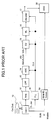
- FIG.1 is a diagram showing an example of a circuit configuration of a conventional data reproducing apparatus.
- An optical head 11 reproduces a signal from a recording medium 10 such as an optical disk or a magneto-optical disc.
- a recording medium 10 such as an optical disk or a magneto-optical disc.
- an SUM/ID detector 19 detects address information from a SUM signal or a Wobble signal, and then an ODC (optical control circuit) 20 recognizes the address.
- a reference clock CLK is made from a PLL (Phase-Locked Loop) 18 synchronizing with a signal from a clock mark provided on the recording medium 10 for reproducing data.
- a signal process is conducted based on this reference clock CLK and then data is detected.
- a reproduction signal from the optical head 11 is amplified by an amplifier 12, a high frequency noise is eliminated by a LPF (low pass filter) 13, and then the reproduction signal is supplied to an ADC (A/D converter) 14.
- a high-pass filter is not shown in FIG.1 but is generally provided for low-pass fluctuation suppression and circuit saturation prevention.
- an analog equalizer may be used for waveform equalization.
- the ADC 14 samples by a reference clock CLK supplied from the PLL 18.
- a phase of the reproduction signal may be shifted from that of the clock synchronized with the clock mark formed by the pre-pit. For this reason, the phase of the reference clock CLK (not shown in FIG.1) may be adjusted.
- An EQ (digital equalizer) 15 equalizes and forms a waveform based on a sample value sampled by the ADC 14. Then, the sample value is equalized into a PR (Partial Response) signal.
- the PR signal is detected by a ML (most-likelihood) detector 16 and then is decoded by a decoder 17.
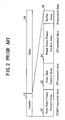
- FIG.2 is a schematic diagram showing an example of a format.
- a simplified 2K ECC Block disk format of AS-MO (Advanced Storage-Magneto Optical Disk) Physical Specifications (Version1.0 April 1998) is shown.
- a header 21 is provided before data part 29 and either one of 2T-repeated data in which a bit string "1100" is formed, and 8T-repeated data in which a bit string "1111111100000000" is formed, is recorded.
- an Auto Read Power Control Area 22 is to be used in order to measure amplitude of the 2T-repeated data and the amplitude of the 8T-repeated data and to adjust reproduction power.
- An Auto Gain Control Area 23 is used to adjust the amplification gain of a signal.
- a Read Clock Phase Control Area 24 is used to adjust the phase of the reference clock CLK made by PLL synchronization with the clock mark mentioned above, with the phase of the clock for sampling a data signal.
- a Buffer Area 25 is provided before the data part 29.
- bit density and track density may be enlarged.
- PRML Partial Response Maximum Likelihood
- the cross-write is a phenomenon in which when data is recorded on a track to be recorded by higher power than optimal power, the data is also recorded on an adjacent track of the track.
- the cross-write deletes information currently recorded on the adjacent track. Thus, an information signal quality of the adjacent track is deteriorated.
- a heat distribution on an optical disk is controlled by properly conducting strobe luminescence and power adjustment of a LD (Laser Diode), so as to avoid the cross-write.
- Crosstalk is a phenomenon in which the adjacent track signal intermixes in a beam spot when data is reproduced and a jitter is caused in the signal to be reproduced. Especially if the track density becomes higher, the crosstalk cannot be avoided..
- the conventional technology Japanese Laid-Open Patent Application No.58-121138, Japanese Laid-Open Patent Application No.5-205280
- Japanese Laid-Open Patent Application No.58-121138 Japanese Laid-Open Patent Application No.5-205280
- the adjacent track signal is also simultaneously reproduced by three beams, and the crosstalk is canceled by adjusting and deducting gain.
- three beams are needed in order to carry out simultaneous reproduction of the adjacent track signal in this conventional technology, it is difficult to adjust phase differences by distance differences among the three beams.
- a reproduction waveform by scanning two tracks including an adjacent track by one beam is sampled by an ADC (Analog to Digital Converter), and a sample value is stored in a storage area, beforehand.
- the sample value is used and the crosstalk is cancelled when data recorded on a target track is reproduced.
- the ADC which converts one sample value into 6 bit (through 8 bit) data, is used.
- the huge storing area that is, 6 bit (through 8 bit) x sample number (waveform length in which the crosstalk is cancelled) x two tracks, is needed as a storage area.
- the pre-pit signal and the Wobble signal in an area to which address information is stored depend on a diameter of the beam spot. If track density is raised, the pre-pit signal or the Wobble signal is influenced by the adjacent track signal before an MO signal that read data information (such as user data). Consequently, crosstalk data cannot be reproduced. For this reason, in a conventional technology (Laid-Open Patent Application No.8-231139), a method of suppressing interference is proposed in that an adjacent pre-pit signal is shifted in a direction of arranging bits. However, in such a configuration, since an additional area is needed in the direction of arranging bits, a format effect becomes degraded. Even in such the configuration, when the track density is raised further, the crosstalk occurs.
- a more specific object of the present invention is to provide the apparatus for reproducing recorded data that generates a crosstalk signal by reproducing an adjacent track while simultaneously reading a target track and at least one adjacent track by one beam, and cancels the crosstalk by deducting the crosstalk signal from the reproduction signal.
- an apparatus for reproducing recorded data by decoding a reproduction signal read from the recorded data recorded on a recording medium in accordance with a predetermined algorithm including: a crosstalk signal generating part generating a crosstalk signal by converting adjacent data recorded on an adjacent track into a waveform of the reproduction signal; and a crosstalk signal eliminating part eliminating the crostalk signal by deducting from the reproduction signal, wherein the reproduction signal in which the crosstalk signal is eliminated is decoded in accordance with the predetermined algorithm and reproduced.
- the apparatus for reproducing recorded data it is possible to generate the crosstalk signal from the adjacent rack and eliminate the corsstalk signal, which is generated, from the reproduction signal from the target track to be reproduced.
- the apparatus may further include a storing part having at least one memory and storing detected data detected by the predetermined algorithm when the recorded data is user data, wherein the crosstalk signal generating part generates the crosstalk signal by converting the detected data stored in the storing part into the waveform of the reproduction signal, and the reproduction signal showing the user data, in which the crosstalk signal is eliminated by the crosstalk signal eliminating part, is decoded by the predetermined algorithm and reproduced.
- the detected data detected in accordance with the predetermined algorithm is stored and also the detected data is a bit value, it can be realized to eliminate the crosstalk by less storage area.
- the apparatus may further include a measurement data recording part recording a predetermined measurement data to measure a crosstalk amount; and an elimination ratio obtaining part obtaining the crosstalk amount based on the measurement data read from the recording medium and obtaining a crosstalk elimination ratio, wherein the crosstalk signal generated by the crosstalk signal generating part is eliminated from the reproduction signal based on the crosstalk elimination ratio.
- the apparatus it is possible to obtain the precise crosstalk amount by reading the predetermined measurement data recorded on the recording medium. Also, it is possible to variably eliminate the crosstalk signal from the reproduction signal by the crosstalk elimination ratio.
- the apparatus may further include a zero data storing part storing zero data only wherein the crosstalk signal generating part obtains the zero data from the zero data storing part when the crosstalk signal is not generated.
- the crosstalk signal is generated base on the zero data. As a result, the crosstalk signal is not generated. Therefore, it is possible to realize the media compatibility for a recording medium where data is recorded by another recording apparatus.
- the apparatus may further include a read signal converting part converting decoded data into a read signal for reading the recorded data recorded on the recording medium, wherein the storing part stores the decoded data, the read signal converting part converts the decoded data stored by the storing part into the read signal, and the crosstalk signal generating part converts the read signal converted by the read signal converting part into the waveform of the reproduction signal.
- data decoded and output as reproduction data can be converted into the reproduction signal. Therefore, even in a case of using a code, such as a run length limited code, having a longer length after encoded than before encoded, it is possible to eliminate the crosstalk signal from the reproduction signal.
- a code such as a run length limited code
- the apparatus may further includes a read signal converting part converting corrected data into the read signal for reading the recorded data recorded on the recording medium, wherein the storing part converts the corrected data stored by the storing part into the read signal and the crosstalk signal generating part converts the read signal converted by the read signal converting part into the waveform of the regeneration signal.
- the crosstalk signal is generated from data in which error is corrected, it is possible to eliminate a more precise crosstalk signal from the reproduction signal.
- the apparatus may further includes a read controlling part controlling to read the recorded data recorded on a target track to be reproduced by an off-track, wherein the crosstalk signal eliminating part eliminates an actual crosstalk signal caused by the off-track from one side of an adjacent track, by deducting the crosstalk signal generated by the crosstalk signal generating part from the reproduction signal.
- the apparatus may further includes a target reproduction signal storing part storing the reproduction signal read from a target track to be reproduced, wherein: the storing part includes two memories and stores a previous detected data detected from a previous track of the target track and a next detected data detected from a next track of the target track; the crosstalk signal generating part generates a previous crosstalk signal and a next crosstalk signal based on the previous detected data and the next detected data; and the crosstalk signal eliminating part deducts the previous crosstalk signal and the next crosstalk signal from the reproduction signal stored in the target reproduction signal storing part.
- the storing part includes two memories and stores a previous detected data detected from a previous track of the target track and a next detected data detected from a next track of the target track
- the crosstalk signal generating part generates a previous crosstalk signal and a next crosstalk signal based on the previous detected data and the next detected data
- the crosstalk signal eliminating part deducts the previous crosstalk signal and the next crosstalk signal from the reproduction signal stored in the target reproduction signal
- the crosstalk signal generating part when the recorded data is address information, the crosstalk signal generating part generates the crosstalk signal by converting adjacent address information adjacent to the recorded data into the waveform of the reproduction signal, so that the reproduction signal showing the address information, in which the crosstalk signal is eliminated by the crosstalk signal eliminating part, is decoded in accordance with the predetermined algorithm to reproduce.
- the apparatus it is not required to read the adjacent address information. It is possible to generate the crosstalk signal by converting into the waveform of the reproduction signal.
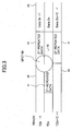
- data is recorded on a recording medium in accordance with a first format as shown in FIG.3.
- FIG.3 is a diagram showing an example of the first format.
- a predetermined signal for example, an area 41 recording 2T-repeated data is arranged so as to shift every track for two tracks in a measurement area of crosstalk.
- a blank area 42 is an area where no data is recorded.
- a data part 29 is shown such as Data 2n-1, Data 2n, and Data 2(n+1)-1 every track.
- an optical beam simultaneously irradiates two tracks T2n-1 and T2n such as a spot 40.
- a state of a reproduction signal reproducing recorded data (data such as user data recorded on a recording medium 10) by emitting an optical beam (not shown) is shown in FIG.4A and FIG.4B.
- FIG.4A and FIG.4B are diagrams showing the state of the reproduction signal.
- the reproduction signal occurs in the area 41 of the 2T-repeated data and the data part 29 at each of the tracks T2n-1 and T2n but does not occur other than in the tracks T2n-1 and T2n.
- the reproduction signal from the track T2n includes the crosstalk as shown in FIG.4B.
- the crosstalk signal from the adjacent track T2n-1 is reproduced such as a signal XT A and the crosstalk signal has the signal amplitude V A depending on a crosstalk amount.
- gate signals Gate A and Gate B are created, the crosstalk amount of each of the gate signals Gate A and Gate B is measured, and signal amplitudes V A and V B are measured.
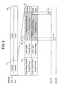
- a conventional existing area can be configured as a measurement area such as a second format shown in FIG.5.
- FIG.5 is a diagram showing an example of the second format.
- a Read Clock Phase Control Area 24 is arranged so as to shift for every track. By forming a stagger, areas for obtaining crosstalk gain are provided. In the example of the second format of FIG.5, the Read Clock Phase Control Area 24 is used as a measurement area of the crosstalk.
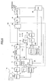
- FIG.6 is a diagram showing a configuration example of a first reproduction circuit.
- a portion 150 surrounded by a dotted line shows a characteristic configuration in the first reproduction circuit.
- the first reproduction circuit includes an optical head 11 for reading recorded data from the recording medium 10, an amplifier 12 for amplifying a reproduction signal, a LPF (low pass filter) 13 for eliminating a high frequency noise, an ADC (A/D converter) 14 for converting the reproduction signal into digital data, a EQ (digital equalizer) 15 for equalizing to a predetermined waveform, a calculator 55 for deducting the crosstalk from the reproduction signal, a ML (most-likelihood) detector 16 for detecting data based on a most-likelihood, a decoder 17 for decoding data and outputting reproduction data, a PLL (Phase Locked Loop) 18 for conducting a phase comparison, a SUM/ID detector 19 for detecting address information, a timing counter and gate generator 50 for generating the timing and the gate signal to
- the reproduction signal in which the optical head 11 reads recorded data on the recording medium 10 is amplified by amplifier 12 and a high frequency noise is eliminated by the LPF 13. Then, the reproduction signal is supplied to the ADC 14.
- the reproduction signal is sampled by the ADC 14 in response to a timing supplied by the timing counter and gate generator 50.
- Sampled data obtained by sampling the reproduction signal is equalized into a predetermined PR (Partial Response) by the EQ 15.
- the SUM/ID detector 19 detects the address information by a SUM signal or a Wobble signal. Based on detected address information, gate signal generated by the timing counter and gate generator 50 is supplied to the P/B detector 60.
- the P/B detector 60 obtains differences between peak values and bottom values as signal amplitudes V A and V B , respectively, in response to the gate signals Gate A and Gate B supplied from the timing counter and gate generator 50.
- the calculator 55 deducts the crosstalk gain XTG A adjusted by the gain adjusting circuit 54 from the sample value that is equalized into the PR waveform by the EQ 15. Then, the crosstalk is cancelled.
- a most likelihood is detected by the ML detector 16 and data is detected based on the detected most likelihood. Then, the decoder 17 decodes the data.
- the ODC 20 When the ODC 20 conducts a crosstalk cancellation, the ODC 20 switches a switch SW1 to the memory 51 in which the detected data of a previous track is stored. On the other hand, when the crosstalk cancellation is conducted to realize a medium compatibility or the crosstalk cancellation is not required because of a small amount of the crosstalk, the switch SW1 is switched to the memory 52 in which only "0" is stored.
- a predetermined PR waveform for example, a PR(1,1) waveform is synthesized from the detected data of the adjacent track stored in the memory 51
- a 1+D operation (D indicates a delay for one clock) is conducted by the 1+D circuit 53 and then an ideal PR waveform for the detected data is produced.
- the detected data, in which the data reproduction is conducted, of the data part 29 of the track T2n-1 is stored in memory 51.
- the calculator 55 deducts the crosstalk gain XTG A in which the gain adjustment is conducted, from the reproduction signal and then the crosstalk is cancelled.
- the reproduction signal of the track T2n, in which the crosstalk is canceled, is output as the reproduction data through the ML detector 16 and the decoder 17.
- the detected data, which is detected by the ML detector 16, of the track T2n is stored in the memory 51 and the detected data is used to cancel the crosstalk for the reproduction signal of a next track.
- the crosstalk cancellation can be realized in a smaller amount of memory than a case where the equalized sample value is stored.
- the peak value and the bottom value are detected by the P/B detector 60 at timing as shown in FIG.7.
- FIG.7 is a diagram showing a sampling example of the PR(1,1) waveform.
- the P/B detector 60 is configured as shown in FIG.8.
- FIG.8 is a diagram showing an example of the circuit configuration of the peak bottom detector.
- the P/B detector 60 includes a peak bottom difference calculating circuit 75, a selector 66 for switching a V A memory 67 and a V B memory 68 in response to a gate signal 74, the V A memory 67 for storing the signal amplitude V A , the V B memory 68 for storing the signal amplitude V B , a cancel gain calculating circuit 69 for calculating crosstalk gain XTG A , and a XTG A memory 70 for storing crosstalk gain XTG A .
- the peak bottom difference calculating circuit 75 includes a selector 61 for distributing the sample value, a counter 62 for counting the predetermined time t, a peak value averaging circuit 63 for calculating an average of the peak value, a bottom value averaging circuit 64 for calculating an average of the bottom value, and an average subtracting circuit 65 for calculating a difference between averages of the peak value and the bottom value.
- the counter 62 In the peak bottom difference calculating circuit 75, based on the clock CLK supplied from the timing counter and gate generator 50 of FIG.6, the counter 62 counts a predetermined number and notifies the selector 61 of the timing for distributing the peak value or the bottom value. In response to the timing notified by the counter 62, the selector 61 distributes the sample value supplied from the EQ 15 to the peak value averaging circuit 63 calculating the average of the peak value, or the bottom value averaging circuit 64 calculating the average of the bottom value.
- the peak value averaging circuit 63 calculates the average of the peak value. Moreover, based on an average number set from the outside, the average of the peak value, in which a difference in a length of the predetermined pattern and a difference in a signal quality are adjusted, is supplied to the average subtracting circuit 65.
- the bottom value averaging circuit 64 calculates average of the bottom value. Moreover, based on an average number set from the outside, the average of the bottom value, in which a difference in the length of the predetermined pattern and the difference in the signal quality are adjusted, is supplied to the average subtracting circuit 65.
- the average subtracting circuit 65 calculates the average difference of peak value and a bottom value.
- the selector 66 In response to the gate signal 74, the selector 66 distributes the average difference from the peak bottom difference calculating circuit 75 as the signal amplitudes V A or V B to the V A memory 67 or the V B memory 68.
- the gain adjusting circuit 54 of FIG. 6 the crosstalk gain XTG A , in which the gain adjustment is conducted for the PR signal, is deducted, and then'the crosstalk is canceled.
- the track jump is conducted at on-track and then is gradually positioned at off-track.
- FIGS.9A, 9B, 9C, and 9D are diagrams showing a sequence example of the crosstalk cancel gain when the track jump is conducted.
- the optical beam is positioned at a spot 90 at on-track by a kickback and the recorded data is reproduced.
- the crosstalk cancel gain is set as "0 (zero).” That is, the memory 52 is selected by the ODC 20 shown in FIG.6.
- the spot 90 is in the state of the on-track at the track T2n-1, and then the spot 90 is gradually positioned to the off-track toward a track T2(n+1)-1.
- the offset is determined using the tracking error signals at the kickback and immediately after the track jump.
- the offset determined for the tracking error signal is conducted, and the crosstalk cancel gain is defined, for example, as "0.5".
- the offset determined for the tracking error signal is conducted, and the crosstalk cancel gain is defined, for example, as "1".
- the crosstalk cancel gain is gradually magnified toward the target track T2(n+1)-1, and the crosstalk cancel gain is magnified more as the accuracy of reproduction data becomes higher.
- An off-track amount is also magnified gradually. Therefore, it is possible to avoid conducting the crosstalk cancellation to the detected data at the track jump of an earlier stage in which many data errors occur.
- the crosstalk cancellation according to the embodiment of the present invention it is possible to avoid conducting the data reproduction that accelerates a data error.
- FIG.10 is a diagram showing a relationship between a successive track reproduction number, and the crosstalk cancel gain.
- the crosstalk cancel gain is gradually increasing from “0 (zero)" until the successive track reproduction number becomes five and the crosstalk cancel gain becomes "1" where the successive track reproduction number is more than five.
- FIG.11 is a diagram showing an optical hard disk format.
- a CAV (Constant Angular Velocity) disk such as shown in FIG.11 includes twelve sectors, each of which has a header part and a data part, on each track.
- a second reproduction circuit which corresponds to a format of the CAV disk and realizes higher speed, can be configured as shown in FIG.12.
- the crosstalk signal memory is provided only for each of outer tracks having a greater number of sectors than inner tracks.
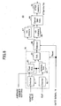
- FIG.12 is a diagram showing a configuration example of the second reproduction circuit.
- circuits that are the same as the ones in FIG.6 are indicated by the same reference numerals and the explanation thereof will be omitted.
- a portion 151 surrounded by a dotted line shows a characteristic configuration in the second reproduction circuit.
- the second reproduction circuit includes the optical head 11 for reading recorded data in the recording medium 10, the amplifier 12 for amplifying the reproduction signal, the LPF 13 for eliminating high frequency noise, the ADC 14 for converting the reproduction signal into digital data, the EQ 15 for equalizing to a predetermined waveform, the calculator 55 for deducting the crosstalk from the reproduction signal, the ML detector 16 for detecting data based on the degree, the decoder 17 for decoding data and outputting reproduction data, the PLL (Phase Locked Loop) 18 for conducting a phase comparison, the SUM/ID detector 19 for detecting address information, the timing counter and gate generator 50 for generating the timing and the gate signal to sample, memories 101 through 112 for storing detected data, the memory 52 for storing "0 (zero)" data only, the 1+D circuit 53 for generating the PR(1,1) waveform, the gain adjusting circuit 54 for adjusting crosstalk gain, the P/B (peak/bottom) detector 60 for detecting the peak and bottom of sample data, and the ODC
- the ODC 20 controls switches SW2 and SW3 and switches to one of the memories.
- the detected data detected from each sector is stored in each of the memories 101 through 112, and the detected data is used to cancel the crosstalk.
- the same method for canceling crostalk as that of the first reproduction circuit shown in FIG.6 can be applied.
- the same number of memories as the number of tracks are further provided in a single memory for each sector.
- FIG.13 is a diagram showing a memory configuration example inside the single memory for each sector.
- the memory 101 shown in FIG.12 includes a set of memories 101-01, 101-02,..., 101-(x-1), 101-x corresponding to tracks T1 through Tx, respectively.
- Switches SW4 and SW5 are controlled by the ODC 20 and then one of the memories 101-01, 101-02,..., 101-(x-1), 101-x is switched.
- the detected data detected by the ML detector 16 are stored in the memories shown in FIG.12 and FIG.13, it is possible to reduce a'memory amount less than a case of storing the sample values for each sector or each track.
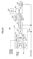
- a third reproduction circuit is configured as shown in FIG.14, so as to cancel the crosstalk.
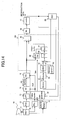
- FIG.14 is a diagram showing a configuration example of the third reproduction circuit.
- circuits that are the same as the ones in FIG.6 are indicated by the same reference numerals and the explanation thereof will be omitted.
- a portion 152 surrounded by a dotted line shows a characteristic configuration in the third reproduction circuit.
- the third reproduction circuit includes the optical head 11 for reading recorded data in the recording medium 10, the amplifier 12 for amplifying the reproduction signal, the LPF (low pass filter) 13 for eliminating high frequency noise, the ADC (A/D converter) 14 for converting the reproduction signal into digital data, the EQ 15 for equalizing to a predetermined waveform, the calculator 55 for deducting the crosstalk from the reproduction signal, the ML detector 16 for detecting data based on a most-likelihood, the decoder 17 for decoding data and outputting reproduction data, the PLL (Phase Locked Loop) 18 for conducting a phase comparison, the SUM/ID detector 19 for detecting address information, the timing counter and gate generator 50 for generating the timing and the gate signal to sample, an encoder 80 for encoding decoded data, a NRZ1 (Non-Return-to-Zero) circuit 81 for converting into a LD (laser diode) drive signal, the memory 52 for storing "0 (zero)
- the encoder 80 for encoding decoded data, and the NRZ1 circuit 81 for changing decoded data into a LD drive signal are provided to produce the crosstalk waveform.
- a fourth reproduction circuit is configured shown in FIG.15, so that the crosstalk can be cancelled.
- FIG.15 is a diagram showing a configuration example of the fourth reproduction circuit.
- circuits that are the same as the ones in FIG.14 are indicated by the same reference numerals and the explanation thereof will be omitted.
- a portion 153 surrounded by a dotted line shows a characteristic configuration in the fourth reproduction circuit.
- the fourth reproduction circuit includes the optical head 11 for reading recorded data in the recording medium 10, the amplifier 12 for amplifying the reproduction signal, the LPF (low pass filter) 13 for eliminating high frequency noise, the ADC 14 for converting the reproduction signal into digital data, the EQ 15 for equalizing to a predetermined waveform, the calculator 55 for deducting the crosstalk from the reproduction signal, the ML detector 16 for detecting data based on a most-likelihood, the decoder 17 for decoding data and outputting reproduction data, the PLL (Phase Locked Loop) 18 for conducting a phase comparison, the SUM/ID detector 19 for detecting address information, the timing counter and gate generator 50 for generating the timing and the gate signal to sample, an encoder 82 for encoding decoded data including the ECC, a NRZ1 (Non-Return-to-Zero) circuit 81 for converting into the LD (laser diode) drive signal, the 1+D circuit 53 for generating the PR(1, 1)
- corrected data in which an error is corrected by the ECC 202, is stored in the memory 51. After that, the same reproduction process as the third reproduction circuit shown in FIG.14 is conducted. Thus, it is possible to cancel the crosstalk from the reproduction signal.
- the corrected data in which the error is corrected by the ECC 202, is stored in the memory 51, it is possible to avoid including an error in the crosstalk signal produced.
- FIG.16 is a diagram showing an example of the third format.
- the predetermined signal for example, 2T-repeated data 94 is shifted in the measuring area for measuring the crosstalk for each track in three tracks so as to form a stagger.
- the third format shown in FIG.16 one beam irradiates simultaneously three tracks T3n-1, T3n, and T3n+1 like a spot 93.
- a fifth reproduction circuit in which the crosstalk is cancelled while data recorded in accordance with the third format forming the stagger as shown in FIG.16, will now be described with reference to FIG.17.
- FIG.17 is a diagram showing a configuration example of the fifth reproduction circuit.
- circuits that are the same as the ones in FIG.6 are indicated by the same reference numerals and the explanation thereof will be omitted.
- a portion 154 surrounded by a dotted line shows a characteristic configuration in the fifth reproduction circuit.
- the fifth reproduction circuit includes the optical head 11 for reading recorded data in the recording medium 10, the amplifier 12 for amplifying the reproduction signal, the LPF (low pass filter) 13 for eliminating high frequency noise, the ADC (A/D converter) 14 for converting the reproduction signal into digital data, the EQ 15 for equalizing to a predetermined waveform, a memory 211 for storing the sample data reproduced, a calculator 551 for deducting the crosstalk from the regenerative signal, the ML detector 16 for detecting data based on a most-likelihood, the decoder 17 for decoding data and outputting reproduction data, the PLL (Phase Locked Loop) 18 for conducting a phase comparison, the SUM/ID detector 19 for detecting address information, a timing counter and gate generator 501 for generating the timing and the gate signal-for sampling, memories 511 and 512 for storing the detected data, the memory 52 for storing "0 (zero)" data only, 1+D circuits 531 and 532 for generating the PR(
- the timing counter and gate generator 501 Based on the address information detected by the SUM/ID detector 19, the timing counter and gate generator 501 generates gate signals as a gate A corresponding to a previous track that is before the target track, a gate B corresponding to the target track to be reproduced, and a gate C corresponding to a next track that is after the target track.
- the ODC 210 stores the detected data of the track T3n-1 corresponding to the gate A in the memory 511 by switching a switch SW12, and controls to store the detected data of a track T3n+1 corresponding to the gate C in the memory 512.
- the ODC 210 switches switches SW13 and SW14 to the memory 52 storing "0" only.
- the ODC 210 controls the switch SW11 and enables the calculator 551 to obtain the sample data that is reproduced, from the memory 211.
- the 1+D circuits 531 and 532 produce the ideal PR waveforms for data stored in memories 511 and 512, respectively, by conducting a 1+D process (delay by one clock).
- the gain adjusting circuits 541 and 542 adjust the gain of the crosstalk gain XTG A and XTG C , and supply to the calculator 55.
- the calculator 551 cancels the crosstalk of the track T3n by deducting one crosstalk signal from the previous track T3n-1 and another crosstalk signal from the next track T3n+1, from the reproduction signal from the target track T3n.
- FIG.18 is a diagram showing an effect of the crosstalk cancellation.
- data recorded on the target track and the adjacent tracks are reproduced by one beam and the sampled data of the reproduction signal is stored in the memories.
- the detected data processed by the ML detector 16 is stored the memories 511 and 512 as the reproduction signal of the adjacent track, so as to use as a cancel signal.
- the detected data to store can be set to "0 (zero)" or "1"
- a one-bit data string is stored in the memories 511 and 512. Therefore, it is possible to reduce the memory aount.
- the measurement area of crosstalk is provided and the predetermined signal for measuring crosstalk (for example, the 2T-repeated signal) is provided to form a stagger.
- the predetermined signal for measuring crosstalk for example, the 2T-repeated signal
- the existing areas for example, the Read Clock Phase Control Area or the like
- the existing area forms the measurement area of the crosstalk so as to shift for the adjacent tracks and a shifted portion is used as a buffer area.
- data is sampled in response to the gate signal sent from the timing counter and gate generator 50 or 501.
- the sample value is classified into a peak point and a bottom point, and values at the peak point and the bottom point are averaged so as to obtain the peak value and the bottom value.
- the crosstalk cancel gain can be varied and also the crosstalk cancel gain can be measured when data is reproduced.
- the crosstalk amount in the measurement area of the predetermined pattern can be measured by the cancellation-off operation.
- the track jump In a case in which the track jump is conducted, data recorded on the adjacent track is reproduced while tracking from one or more tracks inner (or outer) than the target track, and then data recorded on the target track is gradually reproduced.
- the recorded data At a first track when the track jump is conducted, the recorded data is reproduced without conducting an off-track.
- the off-track is conducted from the next track to reproduce two tracks simultaneously, and the crosstalk is cancelled to properly reproduce the recorded data.
- the crosstalk cancel gain is set to "0" for the first track and then the crosstalk cancel gain is gradually increased.
- the crosstalk cancel gain becomes "1"
- the crosstalk cancel gain maintains "1". Consequently, it is possible to properly avoid a data error when the track jump is conducted.
- the reproduction process at higher speed can be realized by providing a plurality of memories corresponding to a sector number of one track (in circumferential direction).
- the reproduction process at higher speed can be realized by providing a plurality of memories corresponding to a track number in a radius direction.
- the crosstalk signal generated from at least one adjacent track is deducted from the reproduction signal when the data part (MO part) recorded on the recording medium 10 is reproduced.
- a method for canceling the crosstalk in a case of reproducing an address part (pre-pit part) will now be described.
- FIG.19 is a diagram showing a spot position of the optical beam when the address part is reproduced.
- the optical beam simultaneously irradiates two tracks of the track T2n-1 and the track T2n by a spot 240 shifting toward the adjacent track T2n-1, and the pre-pit parts showing addresses i+m and i are read.
- the address i+m of the adjacent track T2n-1 is known.
- circuits can be configured so as to directly generate the crosstalk from the address i+m.
- FIG.20 is a diagram showing a configuration example of a sixth reproduction circuit.
- the sixth reproduction circuit includes the optical head 11 for reading recorded data in the recording medium 10, the amplifier 12 for amplifying the reproduction signal, the LPF (low pass filter) 13 for eliminating high frequency noise, the ADC (A/D converter) 14 for converting the reproduction signal into digital data, the EQ (digital equalizer) 15 for equalizing to a predetermined waveform, the calculator 55 for deducting the crosstalk from the reproduction signal, the ML detector 16 for detecting data based on a most-likelihood, the decoder 17 for decoding data and outputting reproduction data, a PLL (Phase Locked Loop) 6011 for conducting a phase comparison, the timing counter and gate generator 50 for generating the timing and the gate signal to sample, a 1+D circuit 602 for generating the PR(1,1) waveform, a gain adjusting circuit 603 for adjusting the crosstalk gain, a crosstalk gain calculator 600 for detecting the peak value and bottom value of
- the reproduction signal which read recorded data in the recording medium 10 by the optical head 11 is amplified by the amplifier 12, high frequency noise is eliminated by the LPF 13, and then the reproduction signal is supplied to the ADC 14.
- the reproduction signal is sampled by the ADC 14.
- the sample value obtained by sampling is equalized into a desired PR (Partial Response) waveform by the EQ 15.
- data is detected based on the PR waveform by the ML decoder 16, and decoded and output by the decoder 17.
- a switch SW21 provided to the PLL 6011 is switched to the ADC 14. And the switch SW21 is switched to the EQ 15 in order to synchronize using data so that the data from the EQ 15 is properly sampled as expected by the PRML after leading the sampling data.
- a switching timing is control-led by the ODC 620 or a counter similar to the ODC 620.
- the ODC 620 conducts the crosstalk cancellation
- the ODC 620 supplies a signal showing the address i+m of the adjacent track T2n-1 as an adjacent ID signal to the 1+D circuit 602.
- the ODC 620 supplies all "0 (zero)" not to conduct the crosstalk cancellation.
- the ODC 620 controls a switch SW21 of the PLL 6011.
- the crosstalk gain calculator 600 calculates the crosstalk gain based on a phase difference between the track T2n and the adjacent track T2n-1, and supplies to the gain adjusting circuit 603.
- the 1+D circuit 602 conducts the 1+D process (delay for one clock) and for example, produces the ideal PR waveform for the address i+m adjacent to the track T2n.
- the gain adjusting circuit 603 adjusts the ideal PR waveform produced by the 1+D circuit 602 based on the crosstalk gain calculated by the crosstalk gain calculator 600.
- the calculator 55 deducts the crosstalk gain adjusted by the gain adjusting circuit 603 from the sample value equalized into the PR waveform by the EQ 1-5. Thus, the crosstalk is cancelled. A most-likelihood is detected from the reproduction signal, in which the crosstalk is cancelled, by the ML detector 16, data is detected based on the most-likelihood, and the data is decoded by the decoder 17.
- FIG.21A is a diagram showing a record example of the pre-pit.
- an ID information showing the address i+m is recorded after a predetermined pattern.
- the predetermined pattern is formed by recording the 2T-repeated data (2T convex part) at 2T interval (2T concave part) and the 8T-repeated data (8T convex part) twice at 8t interval (8T concave part).
- the 2T-repeated data is recorded four times at 2T interval and the 2T-repeated data is further recorded once so as to shift the predetermined pattern.
- the ID information showing the address i is recorded after the predetermined pattern. Consequently, the predetermined pattern is recorded so as to shift by 4T from the adjacent track.
- FIG.21B is a diagram showing the reproduction signal of the track T2n-1 only and FIG.21C is a diagram showing the reproduction signal of the track T2n only.
- amplitude of the reproduction signal is higher at the convex part recording data and is lower at the concave part of interval.
- the predetermined pattern is formed at a record position so that a phase of the reproduction signal of the track T2n delays by 2T.
- FIG.21D is a diagram showing a synthesized reproduction signal of the track T2n-1 and the track T2n.
- the reproduction signals shown in FIG.21B and FIG.21C are synthesized to form a synthesized reproduction signal. That is, referring to FIG.21D, the amplitude of the synthesized reproduction signal becomes "2" in the 2T-repeated data part and a level difference is formed on the waveform of the synthesized reproduction signal in the 8T-repeated data part.
- the crosstalk amount is obtained using the level difference on the waveform of the synthesized reproduction signal.
- FIG.22 is a diagram showing an example of waveform change caused by the crosstalk amount and a phase shift.
- the waveform change of an interference-wave which is caused by the crosstalk amount and the phase shift from the adjacent track (for example, the track T2n-1) at the predetermined pattern, is shown.
- the crosstalk amount is shown by a ratio (logarithm of [signal of the track T2n-1]/[signal of the track T2n] ratio (hereinafter, called T2n-1/T2n ratio)) of signals from the track T2n-1 and the track T2n.
- T2n-1/T2n ratio logarithm of [signal of the track T2n-1]/[signal of the track T2n] ratio
- the amplitude is controlled by an AGC (Auto Gain Control) so as to be constant.
- AGC Automatic Gain Control
- FIG.22 it is shown that the T2n-1/T2n ratio showing the crosstalk amount becomes higher when a center of the optical beam shifts more toward a side of the track T2n-1 and the crosstalk amount becomes lower when the center of the optical beam shifts more toward a side of the track T2n.
- FIG.22 as a phase shift sate, three states of a "4T-25% phase shift of T2n" state, a "4T phase shift of T2n” state, and a "4T+25% phase shift of T2n" state are shown.
- the "4T-25% phase of T2n” state shows that the phase of the track T2n is ahead by a 4T-25% phase from the phase of the track T2n-1.
- the "4T phase shift of T2n” state shows that the phase of the track T2n is shifted by a predetermined 4T phase from the track T2n-1.
- the "4T+25% phase shift of T2n” state shows that the phase of the track T2n is delayed from the phase of the track T2n-1.
- a waveform in which the T2n-1/T2n ratio showing the crosstalk amount indicates "0 (zero)" dB and the phase shift between the track T2n-1 and the track T2n indicates the "4T phase shift of T2n" state corresponds to the synthesized reproduction signal shown in FIG.21D.
- the reproduction signal is sampled and an amplitude ratio is calculated by amplitude (Sp-Sb) in the predetermined pattern part and the level difference (Sy-Sz) where the amplitude is changed by the crosstalk, so that the crosstalk amount for canceling the crosstalk can be obtained.
- Sp-Sb amplitude
- Sy-Sz level difference
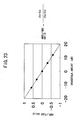
- FIG.23 is a diagram showing a relationship between the amplitude ratio and the crosstalk amount.
- the amplitude difference (Sy-Sz) is approximately 0 (zero) dB.
- the amplitude ratio is approximately 0 (zero) dB.
- the crosstalk amount for the amplitude ratio (gain) "0 (zero)” shows “0 (zero)”.
- FIG.24 is a diagram showing a circuit configuration example of the crosstalk gain calculator.
- the crosstalk gain claculator 600 shown in FIG.20 includes an amplitude value calculating circuit 610 for obtaining an average of the amplitude (Sp-Sb) in the predetermined pattern part and an average of the amplitude (Sy-Sz) changed by the crosstalk, a selector 631 for selecting a memory in response to a gate signal, a Sy-Sz memory 632 for storing the amplitude (Sy-Sz) changed by the crosstalk, a Sp-Sb memory for storing the amplitude (Sp-Sb) in the predetermined pattern part, a map 634 having a relationship table as shown in FIG.23, a decoder 635 for obtaining the crosstalk amount from the amplitude ration by referring to the map 634, and an XTG memory 636 for storing the crosstalk gain.
- the amplitude value calculating circuit 610 includes a counter 611 for counting a clock CLK, a selector 612 for selecting Sy, Sp, Sz, or Sb by counting the sample value by the clock CLK, an averaging circuit 613 for averaging Sy or Sp based on an average number, an averaging circuit 614 for averaging Sz or Sb based on an average number, and a subtractor 615 for calculating an average difference of the averages calculated by the averaging circuit 613 and the averaging circuit 614.
- the amplitude value calculating circuit 610 calculates an average value of sample value Sy by the averaging.circuit 613 and also calculates an average value of sample value Sz by the averaging circuit 614.
- the sample values Sy and Sz are supplied from the selector 612 to the amplitude value calculating circuit 610 every predetermined count number.
- a value resulted in subtracting the average value of the sample value Sz the average value of the sample value Sy is supplied to the selector 631 by the subtractor 615.
- the amplitude value calculating circuit 610 an average value of sample value Sp by the averaging circuit 613 and also calculates an average value of sample value Sb by the averaging circuit 614.
- the sample values Sp and Sb are supplied from the selector 612 to the amplitude value calculating circuit 610 every predetermined count number.
- a value resulted in subtracting the average value of the sample value Sb the average value of the sample value Sp is supplied to the selector 631 by the subtractor 615.
- the selector 631 selects the Sy-Sz memory 632 or the Sp-Sz memory 633 in response to the gate signal, in order to store the average value supplied from the amplitude value calculating circuit 610.
- the decoder 635 calculates the amplitude ratio ((Sy-Sz)/(Sp-Sz)) based on the average value stored in the Sy-Sz memory 632 or the Sp-Sz memory 633, obtains the crosstalk amount for the amplitude ration by referring to the map 634, and stores the crosstalk amount as the crosstalk gain in the XTG memory 636.
- the XTG memory 636 supplies the corsstalk gain to the gain adjusting circuit 603 shown in FIG.20 in response to the gate signal.
- the memory 51 in FIG.6 corresponds to a storing part
- the 1+D circuit 53 corresponds to a crosstalk signal generating part
- the calculator.55 corresponds to a crosstalk signal eliminating part.
- the crosstalk signal from the adjacent track is generated and then the crosstalk signal can be eliminated from the target reproduction signal from the target track to be reproduced. Therefore, it is possible to improve the quality of the reproduction signal from data recorded on the recording medium in which tracks are formed at high density.
- the detected data detected in accordance with the predetermined algorithm is stored and also the detected data is a bit value, it can be realized to eliminate the crosstalk by less storage area.
- the predetermined measurement data is recorded on the recording medium and a precise crosstalk amount can be obtained by reading the measurement data.
Landscapes
- Engineering & Computer Science (AREA)
- Signal Processing (AREA)
- Physics & Mathematics (AREA)
- Algebra (AREA)
- Pure & Applied Mathematics (AREA)
- Optical Recording Or Reproduction (AREA)
- Signal Processing For Digital Recording And Reproducing (AREA)
- Moving Of The Head For Recording And Reproducing By Optical Means (AREA)
Applications Claiming Priority (4)
| Application Number | Priority Date | Filing Date | Title |
|---|---|---|---|
| JP2001072841 | 2001-03-14 | ||
| JP2001072841 | 2001-03-14 | ||
| JP2001288470A JP4498644B2 (ja) | 2001-03-14 | 2001-09-21 | データ再生装置 |
| JP2001288470 | 2001-09-21 |
Publications (3)
| Publication Number | Publication Date |
|---|---|
| EP1244105A2 true EP1244105A2 (de) | 2002-09-25 |
| EP1244105A3 EP1244105A3 (de) | 2006-11-02 |
| EP1244105B1 EP1244105B1 (de) | 2010-01-13 |
Family
ID=26611266
Family Applications (1)
| Application Number | Title | Priority Date | Filing Date |
|---|---|---|---|
| EP01127673A Expired - Lifetime EP1244105B1 (de) | 2001-03-14 | 2001-11-20 | Gerät zur Wiedergabe von aufgezeichneten Daten mit Unterdrückung von Übersprechen von benachbarten Spuren |
Country Status (4)
| Country | Link |
|---|---|
| US (1) | US6724702B2 (de) |
| EP (1) | EP1244105B1 (de) |
| JP (1) | JP4498644B2 (de) |
| DE (1) | DE60141064D1 (de) |
Cited By (2)
| Publication number | Priority date | Publication date | Assignee | Title |
|---|---|---|---|---|
| WO2004059646A1 (en) * | 2002-12-30 | 2004-07-15 | Koninklijke Philips Electronics N.V. | Method for crosstalk reduction between tracks on a recording medium, recording device, playback device and recording medium |
| EP1659577A4 (de) * | 2003-08-29 | 2008-12-31 | Fujitsu Ltd | Datenwiedergabeeinrichtung |
Families Citing this family (23)
| Publication number | Priority date | Publication date | Assignee | Title |
|---|---|---|---|---|
| JP3781286B2 (ja) * | 2001-12-25 | 2006-05-31 | 富士通株式会社 | データ再生装置 |
| US6826140B2 (en) * | 2002-08-26 | 2004-11-30 | Bae Systems Information And Electronic Systems Integration Inc | Multichannel digital recording system with multi-user detection |
| JP4634991B2 (ja) * | 2006-10-24 | 2011-02-16 | 株式会社リコー | 情報再生装置、情報再生方法 |
| US8144984B2 (en) | 2006-12-08 | 2012-03-27 | Canon Kabushiki Kaisha | Image processing apparatus, image processing method, and program for color fringing estimation and compensation |
| JP5003327B2 (ja) * | 2007-07-13 | 2012-08-15 | ソニー株式会社 | データフォーマット、記録媒体、記録装置、記録方法、再生装置、再生方法、及び記録再生装置 |
| JP5349790B2 (ja) * | 2007-11-16 | 2013-11-20 | キヤノン株式会社 | 画像処理装置、画像処理方法、及びプログラム |
| JP4986820B2 (ja) * | 2007-11-16 | 2012-07-25 | キヤノン株式会社 | 画像処理装置及び画像処理方法 |
| JP5047048B2 (ja) * | 2008-04-30 | 2012-10-10 | キヤノン株式会社 | 画像処理装置、撮像装置、制御方法、プログラム、及び記憶媒体 |
| US8300339B1 (en) | 2009-10-01 | 2012-10-30 | Marvell International Ltd. | Method and system for compensating for adjacent tracks during reading of data |
| US8416659B1 (en) * | 2009-12-16 | 2013-04-09 | Marvell International Ltd. | Method and apparatus to correct distortion |
| US8638513B1 (en) | 2010-04-08 | 2014-01-28 | Marvell International Ltd. | Method and system for compensating for adjacent tracks during reading of data |
| US8599508B1 (en) | 2010-04-08 | 2013-12-03 | Marvell International Ltd. | Method and system for compensating for adjacent tracks during reading of data |
| US8837074B1 (en) | 2010-04-16 | 2014-09-16 | Marvell International, Ltd. | Method and system for compensating for track squeeze |
| US8817400B1 (en) * | 2010-11-10 | 2014-08-26 | Marvell International Ltd. | Storage device interface for shingled magnetic recording system |
| US8625215B1 (en) | 2011-03-21 | 2014-01-07 | Marvell International Ltd. | Method and system for compensating for adjacent tracks during writing of data |
| JP2012226789A (ja) * | 2011-04-15 | 2012-11-15 | Hitachi Consumer Electronics Co Ltd | 情報再生装置および情報再生方法 |
| US8830612B2 (en) * | 2011-09-30 | 2014-09-09 | Lsi Corporation | Hardware-based inter-track interference mitigation in magnetic recording systems with read channel storage of cancelation data |
| JP5684169B2 (ja) * | 2012-02-17 | 2015-03-11 | 株式会社東芝 | 記録情報再生装置および記録情報再生方法 |
| US9160373B1 (en) | 2012-09-24 | 2015-10-13 | Marvell International Ltd. | Systems and methods for joint decoding of sector and track error correction codes |
| JP2014130658A (ja) * | 2012-12-28 | 2014-07-10 | Toshiba Corp | コントローラ、ディスク装置、及び再生処理方法 |
| US9438771B2 (en) | 2013-10-08 | 2016-09-06 | Canon Kabushiki Kaisha | Image processing apparatus, image pickup apparatus, image pickup system, image processing method, and non-transitory computer-readable storage medium |
| CN107623816A (zh) | 2013-10-09 | 2018-01-23 | 佳能株式会社 | 图像处理设备、图像拾取设备以及图像处理方法 |
| WO2016006157A1 (ja) * | 2014-07-11 | 2016-01-14 | ソニー株式会社 | 光媒体再生装置および光媒体再生方法 |
Family Cites Families (14)
| Publication number | Priority date | Publication date | Assignee | Title |
|---|---|---|---|---|
| JPS58121138A (ja) | 1982-01-11 | 1983-07-19 | Olympus Optical Co Ltd | 光学的情報記録再生装置 |
| JP3086077B2 (ja) * | 1991-11-19 | 2000-09-11 | パイオニア株式会社 | 光ディスクとその記録信号再生装置 |
| JP3258452B2 (ja) * | 1992-07-21 | 2002-02-18 | パイオニア株式会社 | 光ディスク信号再生装置 |
| JPH06150324A (ja) * | 1992-11-05 | 1994-05-31 | Pioneer Electron Corp | 光学式記録媒体の信号記録再生方法、光学式記録媒体およびその記録信号再生装置 |
| JP3289804B2 (ja) * | 1994-03-10 | 2002-06-10 | パイオニア株式会社 | 光ディスク及び光ディスク再生装置 |
| JPH07334931A (ja) * | 1994-06-10 | 1995-12-22 | Pioneer Electron Corp | クロストーク除去装置 |
| JP3698790B2 (ja) | 1995-02-15 | 2005-09-21 | 株式会社日立製作所 | 光学的情報再生方法、装置および光学的情報記録媒体 |
| JP3283402B2 (ja) * | 1995-07-03 | 2002-05-20 | 株式会社リコー | 光記録装置 |
| JP3845885B2 (ja) * | 1995-12-20 | 2006-11-15 | ソニー株式会社 | 光ディスク再生装置 |
| JP3800653B2 (ja) * | 1995-12-26 | 2006-07-26 | ソニー株式会社 | クロストーク除去装置 |
| US5748592A (en) * | 1996-02-07 | 1998-05-05 | Matsushita Electric Industrial Co., Ltd. | Disk drive apparatus and disk storage medium for high density recording |
| JPH10222846A (ja) * | 1997-02-04 | 1998-08-21 | Pioneer Electron Corp | 記録媒体再生装置 |
| US6377525B1 (en) * | 1999-11-22 | 2002-04-23 | Sony Corporation | Optical disc apparatus and method for reading information |
| JP2001216652A (ja) * | 1999-11-22 | 2001-08-10 | Sony Corp | 光ディスク再生装置及び情報読取方法 |
-
2001
- 2001-09-21 JP JP2001288470A patent/JP4498644B2/ja not_active Expired - Fee Related
- 2001-11-20 DE DE60141064T patent/DE60141064D1/de not_active Expired - Lifetime
- 2001-11-20 EP EP01127673A patent/EP1244105B1/de not_active Expired - Lifetime
- 2001-11-29 US US09/997,325 patent/US6724702B2/en not_active Expired - Fee Related
Cited By (4)
| Publication number | Priority date | Publication date | Assignee | Title |
|---|---|---|---|---|
| WO2004059646A1 (en) * | 2002-12-30 | 2004-07-15 | Koninklijke Philips Electronics N.V. | Method for crosstalk reduction between tracks on a recording medium, recording device, playback device and recording medium |
| CN100409353C (zh) * | 2002-12-30 | 2008-08-06 | 皇家飞利浦电子股份有限公司 | 减小记录介质上轨道之间串扰的方法、记录设备和编码器 |
| EP1659577A4 (de) * | 2003-08-29 | 2008-12-31 | Fujitsu Ltd | Datenwiedergabeeinrichtung |
| US7554897B2 (en) | 2003-08-29 | 2009-06-30 | Fujitsu Limited | Data reproducer |
Also Published As
| Publication number | Publication date |
|---|---|
| JP2002342938A (ja) | 2002-11-29 |
| DE60141064D1 (de) | 2010-03-04 |
| US6724702B2 (en) | 2004-04-20 |
| EP1244105B1 (de) | 2010-01-13 |
| JP4498644B2 (ja) | 2010-07-07 |
| US20020131351A1 (en) | 2002-09-19 |
| EP1244105A3 (de) | 2006-11-02 |
Similar Documents
| Publication | Publication Date | Title |
|---|---|---|
| EP1244105B1 (de) | Gerät zur Wiedergabe von aufgezeichneten Daten mit Unterdrückung von Übersprechen von benachbarten Spuren | |
| EP0580864B1 (de) | Datenaufzeichnungsmedium, datenaufzeichnungsgerät, datenwiedergabegerät und datenaufzeichnungs/wiedergabegerät | |
| US6724706B1 (en) | Digital adaptive equalizer for different quality signals | |
| US7616395B2 (en) | Information reproduction apparatus | |
| JPH0831092A (ja) | 光ディスク装置 | |
| JP3781286B2 (ja) | データ再生装置 | |
| US5818805A (en) | Reproducing apparatus using an information recording medium wherein multi-bit digital information is represented by a shift amount of a pit edge | |
| US6618338B1 (en) | Data reproduction control method and apparatus, and optical disk unit | |
| JP3597433B2 (ja) | データ再生システムにおけるクロック調整装置及び光ディスク装置 | |
| JP4287856B2 (ja) | データ再生装置 | |
| US6922384B2 (en) | Information reproducing apparatus | |
| US7933180B2 (en) | Optical information reproducing method and apparatus for performing reproduction compensation | |
| US7525887B2 (en) | Playback signal processing apparatus and optical disc device | |
| US20070097825A1 (en) | Waveform reconstructor for optical disk read channel | |
| US5748582A (en) | Information recording medium wherein digital symbols are represented by discrete shift amounts of a pit edge and tracking wobbling pits are shared between adjacent tracks and information recording and reproducing apparatus therefor | |
| JP2002230904A (ja) | 情報再生装置 | |
| NL1008698C2 (nl) | Werkwijze voor het automatisch besturen van de bandbreedte van een golfvorm-equalizer. | |
| US8102744B2 (en) | Recording medium playback device and recording medium playback method | |
| US8238052B2 (en) | Method and apparatus for measuring phase shift in a disk drive having bit-patterned media | |
| JPH0430327A (ja) | 光情報記録媒体 | |
| CN100423096C (zh) | 光信息记录装置和激光控制电路 | |
| JPH11296989A (ja) | リードチャネル回路と光ディスク装置 | |
| KR19990011990A (ko) | 광디스크 플레이어의 정형기 | |
| JP2001357531A (ja) | 光ディスク装置 | |
| JP2007200516A (ja) | 情報再生装置および情報再生方法 |
Legal Events
| Date | Code | Title | Description |
|---|---|---|---|
| PUAI | Public reference made under article 153(3) epc to a published international application that has entered the european phase |
Free format text: ORIGINAL CODE: 0009012 |
|
| AK | Designated contracting states |
Kind code of ref document: A2 Designated state(s): AT BE CH CY DE DK ES FI FR GB GR IE IT LI LU MC NL PT SE TR |
|
| AX | Request for extension of the european patent |
Free format text: AL;LT;LV;MK;RO;SI |
|
| PUAL | Search report despatched |
Free format text: ORIGINAL CODE: 0009013 |
|
| AK | Designated contracting states |
Kind code of ref document: A3 Designated state(s): AT BE CH CY DE DK ES FI FR GB GR IE IT LI LU MC NL PT SE TR |
|
| AX | Request for extension of the european patent |
Extension state: AL LT LV MK RO SI |
|
| RIC1 | Information provided on ipc code assigned before grant |
Ipc: G11B 7/005 20060101ALI20060922BHEP Ipc: G11B 20/10 20060101AFI20020807BHEP Ipc: G11B 20/22 20060101ALI20060922BHEP |
|
| 17P | Request for examination filed |
Effective date: 20061211 |
|
| 17Q | First examination report despatched |
Effective date: 20070116 |
|
| AKX | Designation fees paid |
Designated state(s): DE FR GB |
|
| GRAP | Despatch of communication of intention to grant a patent |
Free format text: ORIGINAL CODE: EPIDOSNIGR1 |
|
| RTI1 | Title (correction) |
Free format text: APPARATUS FOR REPRODUCING RECORDED DATA WITH CROSSTALK CANCELLATION FROM ADJACENT TRACKS |
|
| GRAS | Grant fee paid |
Free format text: ORIGINAL CODE: EPIDOSNIGR3 |
|
| GRAA | (expected) grant |
Free format text: ORIGINAL CODE: 0009210 |
|
| AK | Designated contracting states |
Kind code of ref document: B1 Designated state(s): DE FR GB |
|
| REG | Reference to a national code |
Ref country code: GB Ref legal event code: FG4D |
|
| REF | Corresponds to: |
Ref document number: 60141064 Country of ref document: DE Date of ref document: 20100304 Kind code of ref document: P |
|
| PLBE | No opposition filed within time limit |
Free format text: ORIGINAL CODE: 0009261 |
|
| STAA | Information on the status of an ep patent application or granted ep patent |
Free format text: STATUS: NO OPPOSITION FILED WITHIN TIME LIMIT |
|
| 26N | No opposition filed |
Effective date: 20101014 |
|
| REG | Reference to a national code |
Ref country code: FR Ref legal event code: ST Effective date: 20110801 |
|
| REG | Reference to a national code |
Ref country code: DE Ref legal event code: R119 Ref document number: 60141064 Country of ref document: DE Effective date: 20110601 Ref country code: DE Ref legal event code: R119 Ref document number: 60141064 Country of ref document: DE Effective date: 20110531 |
|
| PG25 | Lapsed in a contracting state [announced via postgrant information from national office to epo] |
Ref country code: FR Free format text: LAPSE BECAUSE OF NON-PAYMENT OF DUE FEES Effective date: 20101130 |
|
| PG25 | Lapsed in a contracting state [announced via postgrant information from national office to epo] |
Ref country code: DE Free format text: LAPSE BECAUSE OF NON-PAYMENT OF DUE FEES Effective date: 20110531 |
|
| PGFP | Annual fee paid to national office [announced via postgrant information from national office to epo] |
Ref country code: GB Payment date: 20131120 Year of fee payment: 13 |
|
| GBPC | Gb: european patent ceased through non-payment of renewal fee |
Effective date: 20141120 |
|
| PG25 | Lapsed in a contracting state [announced via postgrant information from national office to epo] |
Ref country code: GB Free format text: LAPSE BECAUSE OF NON-PAYMENT OF DUE FEES Effective date: 20141120 |