EP1245111B1 - System und verfahren zur verbindung von unterhaltungsgeräten undcomputern unter verwendung eines lokalen cdma-basierten netzes - Google Patents
System und verfahren zur verbindung von unterhaltungsgeräten undcomputern unter verwendung eines lokalen cdma-basierten netzes Download PDFInfo
- Publication number
- EP1245111B1 EP1245111B1 EP01942494A EP01942494A EP1245111B1 EP 1245111 B1 EP1245111 B1 EP 1245111B1 EP 01942494 A EP01942494 A EP 01942494A EP 01942494 A EP01942494 A EP 01942494A EP 1245111 B1 EP1245111 B1 EP 1245111B1
- Authority
- EP
- European Patent Office
- Prior art keywords
- cdma
- control center
- television
- coupled
- vcr
- Prior art date
- Legal status (The legal status is an assumption and is not a legal conclusion. Google has not performed a legal analysis and makes no representation as to the accuracy of the status listed.)
- Expired - Lifetime
Links
- 238000000034 method Methods 0.000 title claims abstract description 6
- 230000005236 sound signal Effects 0.000 claims description 15
- 230000004044 response Effects 0.000 claims description 9
- 238000010586 diagram Methods 0.000 description 10
- 230000005540 biological transmission Effects 0.000 description 6
- 238000001228 spectrum Methods 0.000 description 5
- 230000007480 spreading Effects 0.000 description 2
- 230000001413 cellular effect Effects 0.000 description 1
- 230000008878 coupling Effects 0.000 description 1
- 238000010168 coupling process Methods 0.000 description 1
- 238000005859 coupling reaction Methods 0.000 description 1
- 238000012986 modification Methods 0.000 description 1
- 230000004048 modification Effects 0.000 description 1
Images



Classifications
-
- H—ELECTRICITY
- H04—ELECTRIC COMMUNICATION TECHNIQUE
- H04N—PICTORIAL COMMUNICATION, e.g. TELEVISION
- H04N7/00—Television systems
- H04N7/12—Systems in which the television signal is transmitted via one channel or a plurality of parallel channels, the bandwidth of each channel being less than the bandwidth of the television signal
-
- H—ELECTRICITY
- H04—ELECTRIC COMMUNICATION TECHNIQUE
- H04J—MULTIPLEX COMMUNICATION
- H04J13/00—Code division multiplex systems
-
- H—ELECTRICITY
- H04—ELECTRIC COMMUNICATION TECHNIQUE
- H04N—PICTORIAL COMMUNICATION, e.g. TELEVISION
- H04N5/00—Details of television systems
- H04N5/76—Television signal recording
- H04N5/765—Interface circuits between an apparatus for recording and another apparatus
-
- H—ELECTRICITY
- H04—ELECTRIC COMMUNICATION TECHNIQUE
- H04N—PICTORIAL COMMUNICATION, e.g. TELEVISION
- H04N5/00—Details of television systems
- H04N5/76—Television signal recording
- H04N5/765—Interface circuits between an apparatus for recording and another apparatus
- H04N5/775—Interface circuits between an apparatus for recording and another apparatus between a recording apparatus and a television receiver
Definitions
- the present invention relates generally to the wireless transmission of audio, video and data signals. More particularly, the present invention relates to a local wireless network that uses code division multiple access (CDMA) modulation to connect various home entertainment devices to a central local control center, and to transmit audio, video and data signals between the control center and the various home entertainment devices.
- CDMA code division multiple access
- VCRs video cassette recorders
- personal computers and stereo equipment such as audio tuners, compact disc recorders and stereo speakers.
- stereo equipment such as audio tuners, compact disc recorders and stereo speakers.
- Each of these devices is typically connected to one or more of the other devices or to external signal sources by physical cables.
- cable connections are typically required to connect each television to an external cable or satellite television feed
- each VCR must be connected to a television by one or more cables
- cables are required for delivering audio signals from an audio tuner or compact disk player to stereo speakers
- cables are typically required to connect a personal computer to an internet source in the home such as a telephone jack.
- the present invention is directed to a system and method for interconnecting a plurality of home entertainment devices using a local CDMA-based network, wherein the plurality of home entertainment devices include, for example, a first television and a first video cassette recorder (VCR).
- a first CDMA receiver is coupled to the first television, and a first CDMA transceiver is coupled to the first VCR.
- a control center includes an input port that receives a television signal from a cable or satellite source, and the control center is coupled to the first television set and the first VCR by the local CDMA-based network.
- the control center includes a CDMA receiver that receives signals transmitted with the first CDMA transceiver from the first VCR to the control center.
- the control center also includes a CDMA transmitter that transmits video signals to the first CDMA receiver coupled to the first television, and video signals to the first CDMA transceiver coupled to the first VCR.
- Further devices including further televisions, VCRs, a personal computer, an audio tuner, a compact disc player and audio speakers may also be coupled to the control center by the local CDMA-based network.
- the system also includes a second CDMA receiver coupled to a second television, a third CDMA receiver coupled to a third television, a second CDMA transceiver coupled to a second VCR, and a third CDMA transceiver coupled to a third VCR.
- the CDMA transmitter in the control center transmits video signals to the second CDMA receiver coupled to the second television set, to the third CDMA receiver coupled to the third television set, to the second CDMA transceiver coupled to the second VCR, and to the third CDMA transceiver coupled to the third VCR.
- the CDMA receiver in the control center receives signals transmitted with the second CDMA transceiver from the second VCR, and signals transmitted with the third CDMA transceiver from the third VCR.
- a separate CDMA channel i.e., a different PN spreading code and/or offset
- a separate CDMA channel is used for transmitting signals to each device from the control center. All the CDMA channels used for transmissions to and from the control center preferably correspond to spread spectrum signals broadcast on a common frequency band.
- the CDMA transmitter in the control center transmits the video signals from the control center to the first television on a first CDMA channel, video signals are transmitted from the control center to the second television on a second CDMA channel, video signals are transmitted from the control center to the third television on a third CDMA channel, video signals are transmitted from the control center to the first VCR on a fourth CDMA channel, video signals are transmitted from the control center to the second VCR on a fifth CDMA channel, and video signals are transmitted from the control center to the third VCR on a sixth CDMA channel.
- the first VCR transmits the video signals to the control center on a seventh CDMA channel
- the second VCR transmits the video signals to the control center on an eighth CDMA channel
- the third VCR transmits the video signals to the control center on a ninth CDMA channel.
- a fourth CDMA transceiver is coupled to the first television
- a fifth CDMA transceiver is coupled to the second television
- a sixth CDMA transceiver is coupled to the third television.
- the fourth CDMA transceiver transmits first control signals from the first television to the CDMA receiver in the control center on a tenth CDMA channel
- the fifth CDMA transceiver transmits second control signals from the second television to the CDMA receiver in the control center on an eleventh CDMA channel
- the sixth CDMA transceiver transmits third control signals from the third television to the CDMA receiver in the control center on a twelfth CDMA channel.
- the first control signals represent a television channel selection made by a user of the first television
- the second control signals represent a television channel selection made by a user of the second television
- the third control signals represent a television channel selection made by a user of the third television.
- Each channel selection may be made initially and sent to its respective television through the use of a remote control associated with the particular television.
- the network of the present invention also preferably includes a seventh CDMA transceiver coupled to a personal computer.
- the control center further includes an input port that receives an internet signal from a remote source and transmits an internet signal to the remote source.
- the CDMA receiver in the control center receives internet signals transmitted with the seventh CDMA transceiver from the personal computer to the control center on a further CDMA channel, and the CDMA transmitter in the control center transmits internet signals to the seventh CDMA transceiver coupled to the personal computer on a still further CDMA channel.
- the network of the present invention also optionally includes a CDMA transmitter coupled to an audio tuner, a CDMA transmitter coupled to a compact disc player, a CDMA receiver coupled to a first audio speaker, and a CDMA receiver coupled to a second audio speaker.
- the control center is coupled to the audio tuner, the compact disc player, the first speaker and the second speaker by the local CDMA-based network, and the control center receives audio signals transmitted from the audio tuner and the compact disc player on further different CDMA channels. Additionally, the control center transmits audio signals to the first and second speakers on further different CDMA channels.
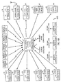
- FIG. 1 there is shown a block diagram of a local CDMA-based network 100 that connects a plurality of home entertainment devices, in accordance with a preferred embodiment of the present invention.
- the home entertainment devices in the network include, for example, televisions 10, 20 and 30; video cassette recorders (VCRs) 40, 50 and 60; a personal computer 70; an audio tuner 80; a compact disc player 90; and audio speakers 96 and 98.
- network 100 need not include all the devices shown in FIG. 1, and that the network may optionally include devices in addition to those shown such as, for example, DVD players.
- local CDMA-based network 100 provides for the coupling of the home entertainment devices described above to each other and to external signal sources, without the use of unsightly physical cables.
- network 100 includes a multi-media control center 1 having an input port 2 that receives a television signal from a cable or satellite source.
- Multi-media control center 1 also preferably includes a further input port 3 that transmits internet signals to and from control center 1.
- port 3 is coupled preferably coupled to an internet service provider via a telephone or cable modem (not shown).
- each home entertainment device in the network is coupled to multi-media control center 1 by one or more CDMA channels.
- a separate CDMA channel (i.e., a different PN spreading code and/or offset) is used for transmitting signals from each home entertainment device in the network to control center 1, and a separate CDMA channel is used for transmitting signals to each device from the control center 1.
- All the CDMA channels used for transmissions to and from the control center preferably correspond to spread spectrum signals broadcast on a common frequency band.
- all the CDMA channels used for transmissions to the control center preferably correspond to spread spectrum signals broadcast on a first frequency band
- all the CDMA channels used for transmissions from the control center preferably correspond to spread spectrum signals broadcast on a second (different) frequency band.
- a CDMA transceiver 11 is coupled to television 10 (TV1). Among other functions, CDMA transceiver 11 transmits channel selection control signals from television 10 (TV1) to control center 1 on a particular CDMA channel, and CDMA transceiver 11 receives video signals transmitted to television 10 (TV1) from control center 1 on a further CDMA channel.
- CDMA transceivers are known in the art. Components for a suitable CDMA transceiver that may be used for implementing the transceivers used in network 100 are shown in U.S. Patent No. 5,101,501 entitled "Method and Apparatus for Providing A Soft Handoff In Communications In A CDMA Cellular Telephone System", which is assigned to the assignee of the present invention.
- a further CDMA transceiver 21 is coupled to television 20 (TV2), and a further CDMA transceiver 31 is coupled to television 30 (TVn).
- CDMA transceiver 21 transmits channel selection control signals transmitted from television 20 (TV2) to control center 1 on a particular CDMA channel, and CDMA transceiver 21 receives video signals transmitted to television 20 (TV2) from control center 1 on a further CDMA channel.
- CDMA transceiver 31 transmits channel selection control signals transmitted from television 30 (TVn) to control center 1 on a particular CDMA channel, and CDMA transceiver 31 receives video signals transmitted to television 30 (TVn) from control center 1 on a still further CDMA channel.
- Each of the channel selection control signals sent by televisions 10, 20, 30 corresponds to a channel that a user of a given television desires to view. As shown in FIG. 1A, channel selection control signals may be generated at a given television in response to actuation by a user of a remote control associated with the given television.
- a CDMA transceiver 41 is coupled to VCR 40 (VCR1). Among other functions, CDMA transceiver 41 receives video signals transmitted to VCR 40 (VCR1) from control center 1 on a particular CDMA channel, and CDMA transceiver 41 transmits video signals from VCR 40 (VCR1) to control center 1 on a further CDMA channel.
- a further CDMA transceiver 51 is coupled to VCR 50 (VCR2).
- CDMA transceiver 51 receives video signals transmitted to VCR 50 (VCR2) from control center 1 on a particular CDMA channel, and CDMA transceiver 51 transmits video signals from VCR 50 (VCR2) to control center 1 on a further CDMA channel.
- a still further CDMA transceiver 61 is coupled to VCR 60 (VCRn).
- CDMA transceiver 61 receives video signals transmitted to VCR 60 (VCRn) from control center 1 on a particular CDMA channel, and CDMA transceiver 61 transmits video signals from VCR 60 (VCRn) to control center 1 on a further CDMA channel.
- CDMA transceiver 41 also optionally transmits channel selection control signals from VCR 40 to control center 1 on a particular CDMA channel
- CDMA transceiver 51 transmits channel selection control signals from VCR 50 to control center 1 on a further CDMA channel
- CDMA transceiver 61 transmits channel selection control signals from VCR 60 to control center 1 on a still further CDMA channel.
- Each of the channel selection control signals sent by VCRs 40, 50, 60 corresponds to a channel that a user of a given VCR desires to record. As shown in FIG. 1A, channel selection control signals may be generated at a given VCR in response to actuation by a user of a remote control associated with the given VCR.
- network 100 also optionally includes a personal computer 70.
- a CDMA transceiver 71 is coupled to the personal computer.
- CDMA transceiver 71 receives internet signals transmitted to personal computer 70 from control center 1 on a particular CDMA channel, and CDMA transceiver 71 transmits internet signals from personal computer 70 to control center 1 on a further CDMA channel.
- an audio tuner 80 is also optionally included in network 100.
- a CDMA transceiver 81 is coupled to the audio tuner 80.
- CDMA transceiver 81 transmits audio signals from audio tuner 80 to control center 1 on a further CDMA channel.
- the audio channel tuned using audio tuner 80 may be selected by a user with a remote control that transmits signals directly to audio tuner 80 (as shown in FIG. 1A), or with a remote a control (such as that shown in FIGS. 1B, 1C) that first transmits a channel selection signal from the remote control to control center 1.
- transceiver 81 also functions to receive channel selection signals (that represent a channel selected by a user via remote control) from control center 1 on a further CDMA channel.
- a compact disk player 90 is also optionally included in network 100.
- a CDMA transceiver 91 is coupled to the compact disk player 90.
- CDMA transceiver 91 transmits audio signals from compact disk player 90 to control center 1 on a further CDMA channel.
- the compact disk number and/or track played by player 90 may be selected by a user with a remote control that transmits control signals directly to compact disk player 90 (as shown in FIG. 1A), or with a remote a control (such as that shown in FIGS. 1B, 1C) that transmits a disk number and/or track selection signal directly from the remote control to control center 1.
- transceiver 91 also functions to receive the disk number and/or track selection signals (that represent a disk number and/or track selected by a user via remote control) from control center 1 on a further CDMA channel.
- network 100 also optionally includes audio speakers 96 and 98, which are respectively coupled to CDMA receivers 97 and 99.
- Each CDMA receiver 97, 99 receives audio signals from control center 1 on a further separate CDMA channel, and the received audio signals are provided to speakers 96, 98.
- the audio signals received by receivers 96, 98 correspond, for example, to audio signals that were first generated at tuner 80 or compact disk player 90, transmitted therefrom to control center 1 on a CDMA channel, and then routed on a further CDMA channel from control center 1 back to speakers 96, 98.
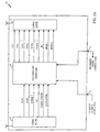
- Control center 100 includes an input port 2 that receives a television signal from a cable or satellite source, and a further input port 3 that transmits internet signals to and from control center 1.
- the control center includes a CDMA receiver 4 that receives: (i) the channel selection signals described above from televisions 10, 20 and 30, (ii) the video and/or channel selection signals described above from VCRs 40, 50 and 60, (iii) the internet signals described above from personal computer 70, (iv) and the audio signals described above from audio tuner 80 and compact disk player 90.
- CDMA receiver 4 then provides each of these received signals to controller/switcher 6.
- the internet signals received on receiver 4 are provided via switcher/controller 6 to port 3 and internet signals from port 3 are also provided to switcher/controller 6 for transmission via CDMA transmitter 5 to personal computer 70.
- Switcher/controller 6 includes software for routing signals input to the switcher (from receiver 4 or tuners 7a, 7b, 7c) to either transmitter 5 or tuners 7a, 7b, 7c.
- Control center 1 also preferably includes a plurality of television tuners 7a, 7b, 7c, each of which is associated with one of the televisions or VCRs in the network.
- Each of the tuners 7a, 7b, 7c is also coupled to port 2 and receives the television signal from the cable or satellite feed described above.
- the channel selection signal received from each television or VCR described above is provided to its respective tuner, which, in response to the channel selection signal, adjusts its tuning circuitry to the television channel corresponding to the channel selection signal.
- a television signal representative of the tuned channel from each tuner 7a, 7b, 7c is then provided back to switcher/controller 6.
- Switcher/controller 6 outputs to CDMA transmitter 5 (i) television signals from tuners 7a, 7b, 7c which are then transmitted by transmitter 5 to televisions 10, 20, 30 and VCRs 40, 50, 60 using the CDMA signals described above, (ii) television signals generated from VCRs 40, 50, 60 (during, for example, playback of a tape) which are then transmitted by transmitter 5 to televisions 10, 20, 30 using the CDMA signals described above, (iii) internet signals from port 3 which are then transmitted by transmitter 5 to personal computer 70 using the CDMA signals described above, and (iv) audio signals from audio tuner 80 and/or compact disk player 90 which are then transmitted by transmitter 5 to speakers 96, 98 using the CDMA signals described above.
- FIG. 2A there is a diagram showing the components of a control center 1a used for routing signals between home entertainment devices in a local CDMA-based network, in accordance with an alternative preferred embodiment of the present invention.
- control' center 1 in the embodiment shown in FIG. 2A the tuning of televisions stations occurs at televisions 10, 20, 30, and VCRs 40, 50, 60, rather than in television tuners disposed within the control center.
- no channel selection signals are transmitted from the televisions 20, 20 , 30 and VCRs 40, 50, 60 to control center 1, and the television signals sent from control center 1 to television 10, 20, 30 and VCR 40, 50, 60 each correspond to the entire spectrum of stations received in port 2.
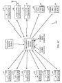
- FIGS. 1B and 1C there are shown block diagrams of local CDMA-based networks 100b, 100c that connect a plurality of home entertainment devices, in accordance with further alternative embodiments of the present invention.
- network 100b the channel selection control signals associated with televisions 10, 20, 30, VCRs 40, 50, 60 and audio tuner 80 are each transmitted from a separate remote control associated with each of the devices to control center 1, and the disk selection/track selection signals associated with compact disk player 90 are transmitted by a remote control associated with compact disk player 90 to control center 1.
- the channel selection control signals associated with televisions 10, 20, 30, VCRs 40, 50, 60 and audio tuner 80 and the disk selection/track selection signals associated with compact disk player 90 are each transmitted from a single universal remote control that communicates with all of the devices to control center 1.
Landscapes
- Engineering & Computer Science (AREA)
- Signal Processing (AREA)
- Multimedia (AREA)
- Computer Networks & Wireless Communication (AREA)
- Two-Way Televisions, Distribution Of Moving Picture Or The Like (AREA)
- Selective Calling Equipment (AREA)
- Small-Scale Networks (AREA)
Claims (18)
- Ein System zum untereinander Verbinden einer Vielzahl von Homeentertainment-Geräten unter Verwendung eines lokalen CDMA-basiertem Netzwerks, wobei die Vielzahl von Homeentertainment-Geräten ein erstes Fernsehgerät und einen ersten Videorekorder (VCR = Videocassettrecorder) enthalten, wobei das System Folgendes aufweist:wobei die Steuerzentrale einen CDMA-Empfänger beinhaltet, der Signale empfängt, die mit dem ersten CDMA-Transceiver von dem ersten VCR zu der Steuerzentrale gesendet werden; undeinen ersten CDMA-Empfänger, der an das erste Fernsehgerät gekoppelt ist;einen zweiten CDMA-Transceiver, der an den ersten VCR gekoppelt ist; eine Steuerzentrale, die einen Eingabeanschluss beinhaltet, der ein Fernsehsignal von einer Kabel- oder Satellitenquelle empfängt, wobei die Steuerzentrale an das erste Fernsehgerät und den ersten VCR mittels des lokalen CDMA-basierten Netzwerkes gekoppelt ist;
wobei die Steuerzentrale einen CDMA-Sender enthält, das Videosignale an den ersten CDMA-Empfänger gekoppelt an das erste Fernsehgerät sendet, und Videosignale an den ersten CDMA-Transceiver, der an den ersten VCR gekoppelt ist, sendet. - System nach Anspruch 1, das weiterhin Folgendes aufweist:wobei die Steuerzentrale an das zweite Fernsehgerät durch das lokale CDMA-basierte Netzwerk gekoppelt ist, und der CDMA-Sender in der Steuerzentrale Videosignale an den zweiten CDMA-Empfänger, der an das zweite Fernsehgerät gekoppelt ist, sendet.einen zweiten CDMA-Empfänger, der an ein zweites Fernsehgerät gekoppelt ist;
- System nach Anspruch 2, das weiterhin Folgendes aufweist:wobei die Steuerzentrale an das dritte Fernsehgerät durch das lokale CDMA-basierte Netzwerk gekoppelt ist, und der CDMA-Sender in der Steuerzentrale Videosignale an den dritten CDMA-Empfänger gekoppelt an das dritte Fernsehgerät sendet.einen dritten CDMA-Empfänger, der an ein drittes Fernsehgerät gekoppelt ist;
- System nach Anspruch 3, das weiterhin Folgendes aufweist:wobei die Steuerzentrale an das zweite VCR durch das lokale CDMA-basierte Netzwerk gekoppelt ist, wobei der CDMA-Empfänger in der Steuerzentrale Signale empfängt, die von dem zweiten CDMA-Transceiver von dem zweiten VCR an die Steuerzentrale gesendet werden, und der CDMA-Sender in der Steuerzentrale Videosignale an den zweiten CDMA-Transceiver, der an den zweiten VCR gekoppelt ist, sendet.einen zweiten CDMA-Transceiver, der an ein zweites VCR gekoppelt ist;
- System nach Anspruch 4, das weiterhin Folgendes aufweist:wobei die Steuerzentrale an den dritten VCR durch das lokale CDMA-basierte Netzwerk gekoppelt ist, wobei der CDMA-Empfänger in der Steuerzentrale Signale empfängt, die von dem dritten CDMA-Transceiver von dem dritten VCR an die Steuerzentrale gesendet werden, und der CDMA-Sender in der Steuerzentrale Videosignale an den dritten CDMA-Transceiver, der an den dritten VCR gekoppelt ist, sendet.einen dritten CDMA-Transceiver, der an einen dritten VCR gekoppelt ist;
- System nach Anspruch 5, wobei der CDMA-Sender in der Steuerzentrale die Videosignale von der Steuerzentrale an den ersten CMDA-Empfänger sendet, der an das erste Fernsehgerät auf einem ersten CDMA-Kanal gekoppelt ist, wobei der CDMA-Sender in der Steuerzentrale die Videosignale von der Steuerzentrale an den zweiten CDMA-Empfänger, der an das zweite Fernsehgerät gekoppelt ist, auf einem zweiten CDMA-Kanal sendet, und der CDMA-Sender in der Steuerzentrale die Videosignale von der Steuerzentrale an den dritten CDMA-Empfänger, der an das dritte Fernsehgerät gekoppelt ist, auf einem dritten CDMA-Kanal sendet.
- System nach Anspruch 6, wobei der CDMA-Sender in der Steuerzentrale die Videosignale von der Steuerzentrale an den ersten CDMA-Transceiver, der an den ersten VCR gekoppelt ist, auf einem vierten CDMA-Kanal sendet, wobei der CDMA-Sender in der Steuerzentrale die Videosignale von der Steuerzentrale an den zweiten CDMA-Transceiver, der an den zweiten VCR gekoppelt ist, auf einem fünften CDMA-Kanal sendet, und wobei der CDMA-Sender in der Steuerzentrale die Videosignale von der Steuerzentrale an den dritten CDMA-Transceiver, der an den dritten VCR gekoppelt ist, auf einem sechsten CDMA-Kanal sendet.
- System nach Anspruch 7, wobei der erste CDMA-Transceiver, der an den ersten VCR gekoppelt ist, die Videosignale zu dem CDMA-Empfänger in der Steuerzentrale auf einem siebten CDMA-Kanal sendet, wobei der zweite CDMA-Transceiver, der an den zweiten VCR gekoppelt ist, die Videosignale an den CDMA-Empfänger in der Steuerzentrale auf einem achten CDMA-Kanal sendet, und wobei der dritte CDMA-Transceiver, der an den dritten VCR gekoppelt ist, die Videosignale auf dem CDMA-Empfänger in der Steuerzentrale auf einem neunten CDMA-Kanal sendet.
- System nach Anspruch 8, das weiterhin Folgendes aufweist:einen vierten CDMA-Transceiver, der an ein erstes Fernsehgerät gekoppelt ist, wobei der vierte CDMA-Transceiver den ersten CDMA-Empfänger gekoppelt an das erste Fernsehgerät enthält;einen fünften CDMA-Transceiver, der an das zweite Fernsehgerät gekoppelt ist, wobei der fünfte CDMA-Transceiver den zweiten CDMA-Empfänger gekoppelt an das zweite Fernsehgerät enthält; undeinen sechsten CDMA-Transceiver, der an das dritte Fernsehgerät gekoppelt ist, wobei der sechste CDMA-Transceiver den dritten CDMA-Empfänger gekoppelt an das dritte Fernsehgerät enthält.
- System nach Anspruch 9, wobei der vierte CDMA-Transceiver, der an das erste Fernsehgerät gekoppelt ist, erste Steuersignale an den CDMA-Empfänger in der Steuerzentrale auf einem zehnten CDMA-Kanal sendet, wobei der fünfte CDMA-Transceiver, der an das zweite Fernsehgerät gekoppelt ist, zweite Steuersignale an den CDMA-Empfänger in der Steuerzentrale auf einem elften CDMA-Kanal sendet und der sechste CDMA-Transceiver, der an das dritte Fernsehgerät gekoppelt ist, dritte Steuersignale an den CDMA-Empfänger in der Steuerzentrale auf einem zwölften CDMA-Kanal sendet.
- System nach Anspruch 10, wobei die ersten Steuersignale eine Fernsehkanalauswahl, ausgeführt durch den Benutzer des ersten Fernsehgeräts, darstellen, wobei dies zweiten Steuersignale eine Fernsehkanalauswahl, ausgewählt durch einen Benutzer des zweiten Fernsehgeräts, darstellen, und die dritten Steuersignale einer Fernsehkanalauswahl, ausgeführt durch einen Benutzer des dritten Fernsehgeräts, darstellen.
- System nach Anspruch 11, wobei die Steuerzentrale weiterhin Folgendes beinhaltet:wobei, ansprechend auf die ersten Steuersignale, der CDMA-Sender in der Steuerzentrale, Videosignale repräsentativ für die Fernsehstation, die von dem ersten Tuner ausgewählt wurde, an den vierten CDMA-Transceiver, der an das erste Fernsehgerät gekoppelt ist, auf dem ersten CDMA-Kanal sendet;einen ersten Tuner, ansprechend auf die ersten Steuersignale, wobei der Tuner das Fernsehsignal von der Kabel- oder Satellitenquelle empfängt und hieraus eine einzelne Fernsehstation auswählt;einen zweiten Tuner, ansprechend auf die zweiten Steuersignale, wobei der Tuner das Fernsehsignal von der Kabel- oder Satellitenquelle empfängt und hieraus eine einzelne Fernsehstation auswählt;einen dritten Tuner, ansprechend auf die dritten Steuersignale, der das Fernsehsignal von der Kabel- oder Satellitenquelle empfängt und hieraus eine einzelne Fernsehstation auswählt;
wobei, ansprechend auf die zweiten Steuersignale, der CDMA-Sender in der Steuerzentrale Videosignale repräsentativ für die Fernsehstation, die von dem zweiten Tuner ausgewählt wurde an dem fünften CDMA-Transceiver, der an das zweite Fernsehgerät gekoppelt ist, auf dem zweiten CDMA-Kanal sendet; und
wobei, ansprechend auf die dritten Steuersignale der CDMA-Sender in der Steuerzentrale Videosignale repräsentativ für die Fernsehstation, ausgewählt durch den dritten Tuner, an den sechsten CDMA-Transceiver, der an das dritte Fernsehgerät gekoppelt ist, auf dem dritten CDMA-Kanal sendet. - System nach Anspruch 12, wobei der erste CDMA-Transceiver, der an den ersten VCR gekoppelt ist, vierte Steuersignale an den CDMA-Empfänger in der Steuerzentrale auf einem dreizehnten CDMA-Kanal sendet, wobei der zweite CDMA-Transceiver, der an den zweiten VCR gekoppelt ist, fünfte Steuersignale an dem CDMA-Empfänger in der Steuerzentrale auf einem vierzehnten CDMA-Kanal sendet, und wobei der dritte CDMA-Transceiver, der an den dritten VCR gekoppelt ist, sechste Steuersignale an den CDMA-Empfänger in der Steuerzentrale auf einem fünfzehnten CDMA-Kanal sendet.
- System nach Anspruch 13, wobei die vierten Steuersignale eine vierte Fernsehkanalaufzeichnungsauswahl, ausgeführt durch einen Benutzer des ersten VCRs, darstellt, wobei die fünften Steuersignale Fernsehkanalaufzeichnungsauswahl, ausgeführt durch einen Benutzer des zweiten VCRs darstellen, und die sechsten Steuersignale eine Fernsehkanalaufzeichnungsauswahl, ausgeführt durch einen Benutzer des dritten VCRs darstellen.
- System nach Anspruch 14, wobei:wobei, ansprechend auf die vierten Steuersignale, der CDMA-Sender in der Steuerzentrale Videosignale repräsentativ für die Fernsehstationsauswahl (ausgeführt durch den ersten Tuner), an den ersten CDMA-Transceiver, der an den ersten VCR gekoppelt ist, auf dem vierten CDMA-Kanal sendet;der erste Tuner weiterhin auf die vierten Steuersignale anspricht;der zweite Tuner weiterhin auf die fünften Steuersignale anspricht;der dritte Tuner weiterhin auf die sechsten Steuersignale anspricht; und
wobei, ansprechend auf die fünften Steuersignale, der CDMA-Sender in der Steuerzentrale Videosignale repräsentativ für die Fernsehstation, ausgewählt durch den zweiten Tuner, an den zweiten CDMA-Transceiver, der an dem zweiten VCR gekoppelt ist, auf dem fünften CDMA-Kanal sendet; und
wobei ansprechend auf die sechsten Steuersignale der CDMA-Sender in der Steuerzentrale Videosignale die repräsentativ sind für die Fernsehstation, die durch den dritten Tuner ausgewählt wurde, an den dritten CDMA-Transceiver, der an den dritten VCR gekoppelt ist, auf dem sechsten CDMA-Kanal sendet. - System nach Anspruch 15, der weiterhin Folgendes aufweist:wobei die Steuerzentrale weiterhin einen Eingabeanschluß beinhaltet, der ein Internetsignal von einer entfernten Quelle empfängt und ein Internetsignal an die entfernte Quelle sendet;einen siebten CDMA-Transceiver, der an einen PC (PC = Personal Computer) gekoppelt ist;
wobei die Steuerzentrale an den PC durch das lokale CDMA-basierte Netzwerk gekoppelt ist; und
wobei der CDMA-Empfänger in der Steuerzentrale Internetsignale empfängt, die von dem siebten CDMÄ-Transceiver von dem PC zu der Steuerzentrale auf einem sechzehnten CMDA-Kanal gesendet werden, und wobei der CDMA-Sender in der Steuerzentrale Internetsignale an den siebten CDMA-Transceiver, der an den PC gekoppelt ist, auf einem siebzehnten CDMA-Kanal sendet. - System nach Anspruch 16, der weiterhin Folgendes aufweist:wobei die Steuerzentrale an den Audio-Tuner, den CD-Spieler, den ersten Lautsprecher und den zweiten Lautssprecher durch das lokale CDMA-basierte Netzwerk gekoppelt ist;einen CDMA-Sender, der an einen Audio-Tuner gekoppelt ist;einen CDMA-Sender, der an einen CD-Spieler gekoppelt ist;einen CDMA-Empfänger, der an einen ersten Lautsprecher gekoppelt ist; undeinen CDMA-Empfänger, der an einen zweiten Lautsprecher gekoppelt ist; undeinen CDMA-Empfänger, der an einem zweiten Lautsprecher gekoppelt ist;
wobei der CDMA-Empfänger in der Steuerzentrale Audiosignale empfängt, die von dem Audio-Tuner an die Steuerzentrale auf einem achtzehnten CDMA-Kanal gesendet werden, wobei der CDMA-Empfänger in der Steuerzentrale Audio-Signale, die von dem CD-Spieler an die Steuerzentrale auf einem neunzehnten CDMA-Kanal gesendet werden, empfängt; und
wobei der CDMA-Sender in der Steuerzentrale Audio-Signale an den ersten Lautsprecher auf einem zwanzigsten CDMA-Kanal sendet und der CDMA-Sender in der Steuerzentrale Audio-Signal an den zweiten Lautsprecher auf einem einundzwanzigsten CDMA-Kanal sendet. - Ein Verfahren zum Verbinden einer Vielzahl von Homeentertainment- bzw. Unterhaltungsgeräten unter Verwendung eines lokalen CDMA-basierten Netzwerks, wobei die Vielzahl von Homeentertainment-Geräten ein erstes Fernsehgerät und einen Videorekorder (VCR = Videocassettrecorder) beinhalten, wobei das Verfahren die folgenden Schritte aufweist:Vorsehen eines ersten CDMA-Empfängers, der an das erste Fernsehgerät gekoppelt ist;Vorsehen eines ersten CDMA-Transceivers, der an den ersten VCR gekoppelt ist;Vorsehen einer Steuerzentrale, die einen Eingangsanschluss bzw. - port besitzt, der ein Fernsehsignal von einer Kabel- oder Satellitenquelle empfängt, wobei die Steuerzentrale an das erste Fernsehgerät und den ersten VCR mittels des lokalen CDMA-basierten Netzwerkes gekoppelt ist;Empfangen mit einem CDMA-Empfänger, bei der Steuerzentrale, von Signalen, die von dem ersten CDMA-Transceiver von dem ersten VCR zu der Steuerzentrale gesendet werden;Senden, mit einem CDMA-Sender bei der Steuerzentrale, von Videosignalen an den ersten CDMA-Empfänger, der an das erste Fernsehgerät gekoppelt ist; undSenden mit dem CDMA-Sender bei der Steuerzentrale, von Videosignalen an den ersten CDMA-Transceiver, der an den ersten VCR gekoppelt ist.
Applications Claiming Priority (3)
| Application Number | Priority Date | Filing Date | Title |
|---|---|---|---|
| US47982800A | 2000-01-07 | 2000-01-07 | |
| US479828 | 2000-01-07 | ||
| PCT/US2001/000578 WO2001052534A2 (en) | 2000-01-07 | 2001-01-08 | System and method for connecting home entertainment and computer devices using a local cdma-based network |
Publications (2)
| Publication Number | Publication Date |
|---|---|
| EP1245111A2 EP1245111A2 (de) | 2002-10-02 |
| EP1245111B1 true EP1245111B1 (de) | 2005-12-14 |
Family
ID=23905608
Family Applications (1)
| Application Number | Title | Priority Date | Filing Date |
|---|---|---|---|
| EP01942494A Expired - Lifetime EP1245111B1 (de) | 2000-01-07 | 2001-01-08 | System und verfahren zur verbindung von unterhaltungsgeräten undcomputern unter verwendung eines lokalen cdma-basierten netzes |
Country Status (9)
| Country | Link |
|---|---|
| EP (1) | EP1245111B1 (de) |
| JP (1) | JP2003520508A (de) |
| KR (1) | KR100705893B1 (de) |
| CN (1) | CN1245023C (de) |
| AT (1) | ATE313214T1 (de) |
| AU (1) | AU2931601A (de) |
| DE (1) | DE60115838T2 (de) |
| ES (1) | ES2253389T3 (de) |
| WO (1) | WO2001052534A2 (de) |
Families Citing this family (2)
| Publication number | Priority date | Publication date | Assignee | Title |
|---|---|---|---|---|
| US6975364B2 (en) * | 2002-06-13 | 2005-12-13 | Hui-Lin Lin | Radio television and frequency modulation monitor transmitting receiving control apparatus |
| JP4341539B2 (ja) * | 2004-12-07 | 2009-10-07 | 株式会社日立製作所 | 受信装置及び受信アンテナ設定方法 |
Family Cites Families (12)
| Publication number | Priority date | Publication date | Assignee | Title |
|---|---|---|---|---|
| NL8300467A (nl) * | 1983-02-08 | 1984-09-03 | Philips Nv | Draagbaar electronisch beeld-opname systeem. |
| GB9121203D0 (en) * | 1991-10-04 | 1991-11-20 | D2B Systems Co Ltd | Local communication bus system and apparatus for use in such a system |
| JPH0630470A (ja) * | 1992-07-10 | 1994-02-04 | Matsushita Electric Ind Co Ltd | ホームバスコントローラ |
| JPH0923207A (ja) * | 1995-07-07 | 1997-01-21 | Toshiba Corp | 情報多重化方式 |
| JPH1013918A (ja) * | 1996-06-19 | 1998-01-16 | Toshiba Corp | 符号分割多元接続方式を採用した移動通信システムとその無線通信装置 |
| JPH10112724A (ja) * | 1996-10-07 | 1998-04-28 | Hitachi Ltd | 家庭内av−lanシステム |
| US5999525A (en) | 1996-11-18 | 1999-12-07 | Mci Communications Corporation | Method for video telephony over a hybrid network |
| JPH10285197A (ja) * | 1997-04-04 | 1998-10-23 | Yozan:Kk | 通信システム |
| JP3887945B2 (ja) * | 1997-05-09 | 2007-02-28 | ソニー株式会社 | データ受信装置及びデータ受信方法 |
| EP1294188A1 (de) * | 1997-08-13 | 2003-03-19 | Canal + Technologies | Videoaufnahmesteuerung |
| JP3864513B2 (ja) * | 1997-09-18 | 2007-01-10 | ソニー株式会社 | 電子機器システム及び電子機器システムの制御方法 |
| JPH11155165A (ja) * | 1997-11-21 | 1999-06-08 | Toshiba Corp | 移動通信システム、基地局装置および制御局装置 |
-
2001
- 2001-01-08 EP EP01942494A patent/EP1245111B1/de not_active Expired - Lifetime
- 2001-01-08 AT AT01942494T patent/ATE313214T1/de not_active IP Right Cessation
- 2001-01-08 JP JP2001552627A patent/JP2003520508A/ja active Pending
- 2001-01-08 WO PCT/US2001/000578 patent/WO2001052534A2/en not_active Ceased
- 2001-01-08 CN CNB018035213A patent/CN1245023C/zh not_active Expired - Fee Related
- 2001-01-08 AU AU29316/01A patent/AU2931601A/en not_active Abandoned
- 2001-01-08 KR KR1020027008773A patent/KR100705893B1/ko not_active Expired - Fee Related
- 2001-01-08 ES ES01942494T patent/ES2253389T3/es not_active Expired - Lifetime
- 2001-01-08 DE DE60115838T patent/DE60115838T2/de not_active Expired - Lifetime
Also Published As
| Publication number | Publication date |
|---|---|
| KR20020074191A (ko) | 2002-09-28 |
| ATE313214T1 (de) | 2005-12-15 |
| DE60115838D1 (de) | 2006-01-19 |
| JP2003520508A (ja) | 2003-07-02 |
| WO2001052534A2 (en) | 2001-07-19 |
| KR100705893B1 (ko) | 2007-04-10 |
| EP1245111A2 (de) | 2002-10-02 |
| HK1050795A1 (en) | 2003-07-04 |
| WO2001052534A3 (en) | 2002-01-24 |
| ES2253389T3 (es) | 2006-06-01 |
| CN1245023C (zh) | 2006-03-08 |
| AU2931601A (en) | 2001-07-24 |
| DE60115838T2 (de) | 2006-08-24 |
| CN1394439A (zh) | 2003-01-29 |
Similar Documents
| Publication | Publication Date | Title |
|---|---|---|
| US6996837B1 (en) | Terminal equipment for cable television | |
| EP0488289B1 (de) | Videonetzwerksystem | |
| US8055364B2 (en) | System and method for request, delivery and use of multimedia files for audiovisual entertainment | |
| US20020026552A1 (en) | System and method for switching signals over twisted-pair wires | |
| JPH027687A (ja) | 信号分配ケーブルネットワークシステム | |
| JP2000511734A (ja) | Dbsとケーブルtvのためのプログラムガイド | |
| JP2004532574A (ja) | ディジタル・ケーブル準拠装置において用いられる無線通信podモジュール | |
| US7584494B2 (en) | Cable to wireless conversion system for in-home video distribution | |
| KR20010070480A (ko) | 전자 기기 시스템 | |
| EP1245111B1 (de) | System und verfahren zur verbindung von unterhaltungsgeräten undcomputern unter verwendung eines lokalen cdma-basierten netzes | |
| US20050223407A1 (en) | Wireless local area audio/visual information distribution system and method by impulse radio | |
| US20030177499A1 (en) | Radio frequency distribution network system | |
| JPH10336614A (ja) | 集合住宅マルチメディアシステム | |
| HK1050795B (en) | System and method for connecting home entertainment and computer devices by a local cdma-based network | |
| WO2001028241A1 (en) | Wireless data jack for set top boxes | |
| JPH0715619A (ja) | ワイヤレスav信号送受信機 | |
| KR19980087256A (ko) | 확장된 플레이 라디오 영상 카세트 녹음기 시스템 및 그 시스템의 동작 방법 | |
| KR200323208Y1 (ko) | 무선통신방식을 이용한 원격제어 에이브이 송수신 시스템 | |
| WO2006101179A1 (ja) | 伝送システム、送信側伝送器、伝送方法、及びコンピュータプログラム | |
| JP2899229B2 (ja) | 端末補償増幅器 | |
| JPH1169272A (ja) | テレビジョン信号送信器及びそのテレビジョン信号送信器を用いた映像機器 | |
| KR20040086866A (ko) | 무선통신방식을 이용한 원격제어 에이브이 송수신 시스템 | |
| US20030061616A1 (en) | Re-broadcasting systems and methods using automatic gain control | |
| JPH0630470A (ja) | ホームバスコントローラ | |
| MXPA99000516A (en) | Methods and systems for providing information to a television using a personal computer |
Legal Events
| Date | Code | Title | Description |
|---|---|---|---|
| PUAI | Public reference made under article 153(3) epc to a published international application that has entered the european phase |
Free format text: ORIGINAL CODE: 0009012 |
|
| 17P | Request for examination filed |
Effective date: 20020708 |
|
| AK | Designated contracting states |
Kind code of ref document: A2 Designated state(s): AT BE CH CY DE DK ES FI FR GB GR IE IT LI LU MC NL PT SE TR |
|
| AX | Request for extension of the european patent |
Free format text: AL;LT;LV;MK;RO;SI |
|
| GRAP | Despatch of communication of intention to grant a patent |
Free format text: ORIGINAL CODE: EPIDOSNIGR1 |
|
| GRAS | Grant fee paid |
Free format text: ORIGINAL CODE: EPIDOSNIGR3 |
|
| GRAA | (expected) grant |
Free format text: ORIGINAL CODE: 0009210 |
|
| AK | Designated contracting states |
Kind code of ref document: B1 Designated state(s): AT BE CH CY DE DK ES FI FR GB GR IE IT LI LU MC NL PT SE TR |
|
| PG25 | Lapsed in a contracting state [announced via postgrant information from national office to epo] |
Ref country code: BE Free format text: LAPSE BECAUSE OF FAILURE TO SUBMIT A TRANSLATION OF THE DESCRIPTION OR TO PAY THE FEE WITHIN THE PRESCRIBED TIME-LIMIT Effective date: 20051214 Ref country code: AT Free format text: LAPSE BECAUSE OF FAILURE TO SUBMIT A TRANSLATION OF THE DESCRIPTION OR TO PAY THE FEE WITHIN THE PRESCRIBED TIME-LIMIT Effective date: 20051214 Ref country code: NL Free format text: LAPSE BECAUSE OF FAILURE TO SUBMIT A TRANSLATION OF THE DESCRIPTION OR TO PAY THE FEE WITHIN THE PRESCRIBED TIME-LIMIT Effective date: 20051214 Ref country code: CH Free format text: LAPSE BECAUSE OF FAILURE TO SUBMIT A TRANSLATION OF THE DESCRIPTION OR TO PAY THE FEE WITHIN THE PRESCRIBED TIME-LIMIT Effective date: 20051214 Ref country code: LI Free format text: LAPSE BECAUSE OF FAILURE TO SUBMIT A TRANSLATION OF THE DESCRIPTION OR TO PAY THE FEE WITHIN THE PRESCRIBED TIME-LIMIT Effective date: 20051214 |
|
| REG | Reference to a national code |
Ref country code: GB Ref legal event code: FG4D |
|
| REG | Reference to a national code |
Ref country code: CH Ref legal event code: EP |
|
| PG25 | Lapsed in a contracting state [announced via postgrant information from national office to epo] |
Ref country code: IE Free format text: LAPSE BECAUSE OF NON-PAYMENT OF DUE FEES Effective date: 20060109 |
|
| REG | Reference to a national code |
Ref country code: IE Ref legal event code: FG4D |
|
| REF | Corresponds to: |
Ref document number: 60115838 Country of ref document: DE Date of ref document: 20060119 Kind code of ref document: P |
|
| PG25 | Lapsed in a contracting state [announced via postgrant information from national office to epo] |
Ref country code: LU Free format text: LAPSE BECAUSE OF NON-PAYMENT OF DUE FEES Effective date: 20060131 Ref country code: MC Free format text: LAPSE BECAUSE OF NON-PAYMENT OF DUE FEES Effective date: 20060131 |
|
| REG | Reference to a national code |
Ref country code: SE Ref legal event code: TRGR |
|
| PG25 | Lapsed in a contracting state [announced via postgrant information from national office to epo] |
Ref country code: DK Free format text: LAPSE BECAUSE OF FAILURE TO SUBMIT A TRANSLATION OF THE DESCRIPTION OR TO PAY THE FEE WITHIN THE PRESCRIBED TIME-LIMIT Effective date: 20060314 Ref country code: GR Free format text: LAPSE BECAUSE OF FAILURE TO SUBMIT A TRANSLATION OF THE DESCRIPTION OR TO PAY THE FEE WITHIN THE PRESCRIBED TIME-LIMIT Effective date: 20060314 |
|
| PG25 | Lapsed in a contracting state [announced via postgrant information from national office to epo] |
Ref country code: PT Free format text: LAPSE BECAUSE OF FAILURE TO SUBMIT A TRANSLATION OF THE DESCRIPTION OR TO PAY THE FEE WITHIN THE PRESCRIBED TIME-LIMIT Effective date: 20060515 |
|
| NLV1 | Nl: lapsed or annulled due to failure to fulfill the requirements of art. 29p and 29m of the patents act | ||
| REG | Reference to a national code |
Ref country code: ES Ref legal event code: FG2A Ref document number: 2253389 Country of ref document: ES Kind code of ref document: T3 |
|
| REG | Reference to a national code |
Ref country code: CH Ref legal event code: PL |
|
| ET | Fr: translation filed | ||
| PLBE | No opposition filed within time limit |
Free format text: ORIGINAL CODE: 0009261 |
|
| STAA | Information on the status of an ep patent application or granted ep patent |
Free format text: STATUS: NO OPPOSITION FILED WITHIN TIME LIMIT |
|
| 26N | No opposition filed |
Effective date: 20060915 |
|
| PG25 | Lapsed in a contracting state [announced via postgrant information from national office to epo] |
Ref country code: TR Free format text: LAPSE BECAUSE OF FAILURE TO SUBMIT A TRANSLATION OF THE DESCRIPTION OR TO PAY THE FEE WITHIN THE PRESCRIBED TIME-LIMIT Effective date: 20051214 |
|
| PG25 | Lapsed in a contracting state [announced via postgrant information from national office to epo] |
Ref country code: CY Free format text: LAPSE BECAUSE OF FAILURE TO SUBMIT A TRANSLATION OF THE DESCRIPTION OR TO PAY THE FEE WITHIN THE PRESCRIBED TIME-LIMIT Effective date: 20051214 |
|
| PGFP | Annual fee paid to national office [announced via postgrant information from national office to epo] |
Ref country code: SE Payment date: 20091223 Year of fee payment: 10 |
|
| PGFP | Annual fee paid to national office [announced via postgrant information from national office to epo] |
Ref country code: GB Payment date: 20091211 Year of fee payment: 10 Ref country code: ES Payment date: 20100115 Year of fee payment: 10 |
|
| PGFP | Annual fee paid to national office [announced via postgrant information from national office to epo] |
Ref country code: FR Payment date: 20100125 Year of fee payment: 10 Ref country code: IT Payment date: 20100116 Year of fee payment: 10 Ref country code: FI Payment date: 20100108 Year of fee payment: 10 |
|
| PGFP | Annual fee paid to national office [announced via postgrant information from national office to epo] |
Ref country code: DE Payment date: 20100129 Year of fee payment: 10 |
|
| REG | Reference to a national code |
Ref country code: SE Ref legal event code: EUG |
|
| GBPC | Gb: european patent ceased through non-payment of renewal fee |
Effective date: 20110108 |
|
| REG | Reference to a national code |
Ref country code: FR Ref legal event code: ST Effective date: 20110930 |
|
| PG25 | Lapsed in a contracting state [announced via postgrant information from national office to epo] |
Ref country code: FR Free format text: LAPSE BECAUSE OF NON-PAYMENT OF DUE FEES Effective date: 20110131 |
|
| PG25 | Lapsed in a contracting state [announced via postgrant information from national office to epo] |
Ref country code: GB Free format text: LAPSE BECAUSE OF NON-PAYMENT OF DUE FEES Effective date: 20110108 Ref country code: FI Free format text: LAPSE BECAUSE OF NON-PAYMENT OF DUE FEES Effective date: 20110108 |
|
| REG | Reference to a national code |
Ref country code: DE Ref legal event code: R119 Ref document number: 60115838 Country of ref document: DE Effective date: 20110802 |
|
| PG25 | Lapsed in a contracting state [announced via postgrant information from national office to epo] |
Ref country code: IT Free format text: LAPSE BECAUSE OF NON-PAYMENT OF DUE FEES Effective date: 20110108 |
|
| REG | Reference to a national code |
Ref country code: ES Ref legal event code: FD2A Effective date: 20120220 |
|
| PG25 | Lapsed in a contracting state [announced via postgrant information from national office to epo] |
Ref country code: ES Free format text: LAPSE BECAUSE OF NON-PAYMENT OF DUE FEES Effective date: 20110109 |
|
| PG25 | Lapsed in a contracting state [announced via postgrant information from national office to epo] |
Ref country code: SE Free format text: LAPSE BECAUSE OF NON-PAYMENT OF DUE FEES Effective date: 20110109 |
|
| PG25 | Lapsed in a contracting state [announced via postgrant information from national office to epo] |
Ref country code: DE Free format text: LAPSE BECAUSE OF NON-PAYMENT OF DUE FEES Effective date: 20110802 |