EP1245165B1 - Dispositif pour monter une visière sur un casque - Google Patents
Dispositif pour monter une visière sur un casque Download PDFInfo
- Publication number
- EP1245165B1 EP1245165B1 EP01309088A EP01309088A EP1245165B1 EP 1245165 B1 EP1245165 B1 EP 1245165B1 EP 01309088 A EP01309088 A EP 01309088A EP 01309088 A EP01309088 A EP 01309088A EP 1245165 B1 EP1245165 B1 EP 1245165B1
- Authority
- EP
- European Patent Office
- Prior art keywords
- shield
- engagement
- fixing structure
- stopper
- structure according
- Prior art date
- Legal status (The legal status is an assumption and is not a legal conclusion. Google has not performed a legal analysis and makes no representation as to the accuracy of the status listed.)
- Expired - Lifetime
Links
- 230000000694 effects Effects 0.000 abstract description 3
- NMFHJNAPXOMSRX-PUPDPRJKSA-N [(1r)-3-(3,4-dimethoxyphenyl)-1-[3-(2-morpholin-4-ylethoxy)phenyl]propyl] (2s)-1-[(2s)-2-(3,4,5-trimethoxyphenyl)butanoyl]piperidine-2-carboxylate Chemical compound C([C@@H](OC(=O)[C@@H]1CCCCN1C(=O)[C@@H](CC)C=1C=C(OC)C(OC)=C(OC)C=1)C=1C=C(OCCN2CCOCC2)C=CC=1)CC1=CC=C(OC)C(OC)=C1 NMFHJNAPXOMSRX-PUPDPRJKSA-N 0.000 description 46
- 238000012423 maintenance Methods 0.000 description 1
- 238000012986 modification Methods 0.000 description 1
- 230000004048 modification Effects 0.000 description 1
- 230000001846 repelling effect Effects 0.000 description 1
Images






Classifications
-
- A—HUMAN NECESSITIES
- A42—HEADWEAR
- A42B—HATS; HEAD COVERINGS
- A42B3/00—Helmets; Helmet covers ; Other protective head coverings
- A42B3/04—Parts, details or accessories of helmets
- A42B3/18—Face protection devices
-
- A—HUMAN NECESSITIES
- A42—HEADWEAR
- A42B—HATS; HEAD COVERINGS
- A42B3/00—Helmets; Helmet covers ; Other protective head coverings
- A42B3/04—Parts, details or accessories of helmets
- A42B3/18—Face protection devices
- A42B3/22—Visors
- A42B3/221—Attaching visors to helmet shells, e.g. on motorcycle helmets
- A42B3/222—Attaching visors to helmet shells, e.g. on motorcycle helmets in an articulated manner, e.g. hinge devices
Definitions
- This invention relates to a fixing structure for shield installed in a full-face type helmet and an open-face type helmet wearing to protect the head part and the face part of a driver when the driver rides on various kinds of motorized vehicles or moving devices such as a motorcycle and an automobile or the like
- the fixing structure described in the gazette is operated such that the shield is turned to the position where the engagement protuberances ride over the stoppers under operation not found in usual use for widening the shield or twisting the shield in consideration of releasing the engagement between the engagement protuberances and the stoppers at a position where the engagement protuberances are contacted with the stoppers in the full-opened upper limit position of the shield, the guide pieces are coincided with the inlet at the aforesaid position to enable it to be removed from the notch of the hub, thereby the shield is removed from the helmet.
- the guide pieces and the engagement steps are always engaged with each other, the engagement protuberances are contacted with the stoppers at the full-opened upper limit position of the shield to prevent it from being turned over the former limit position, so that the shield is not removed from the shell.
- the shield when the shield is removed, the shield can be removed through one-finger touch operation without using a setscrew at all.
- a technical means employed by the present invention to accomplish the aforesaid object relates to a fixing structure for a shield 1 installed at the front surface of a helmet main body, wherein an engagement protuberance 101 is contacted with a stopper 5 at a full-opened upper limit position of the shield 1, and when the engagement protuberance 101 rides over the stopper 5, a guide piece 81 at a hub 82 installed at a fixing part 2 for the shield 1 is released from the engaged state with the engagement step 33 formed at a notch 31 for supporting the hub 82 of the engagement male members B arranged at right and left sides of a helmet A and can be released from an inlet 32 for releasing the guide piece 81 formed at the notch 31, wherein an engagement protuberance 101 is formed with a passing notch 102 having such a size as one through which the stopper 5 can pass, the stopper 5 can be slid against the engagement male member B to be coincided with or removed from the passing notch 102 and integrally engaged while being always biased in a direction repelling from the passing
- the fixing structure described in the gazette of Japanese Patent Publication No. Hei 6-60444 ( EP 0 294 677 A1 ) has a click means positioned in a concentric manner with the supporting part acting as a center of turning operation of the shield.
- the click means is used for adjusting an opening or closing angle during opening or closing of the shield in a stepwise manner, wherein the shield is held at a predetermined position in a resilient manner in a range from the full-closed lower limit position to the full-opened upper limit position.
- the fixing structure of the present invention can be installed in a full-face type helmet.
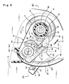
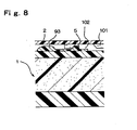
- the engagement protuberance 101 is contacted with the stopper 5 to restrict its more turning operation (refer to Figs. 5 to 8 ).
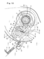
- the hub 82 is released out of the notch 31 and the shield 1 is removed (refer to Fig. 14 ).
- the stopper 5 When the shield 1 is removed, the stopper 5 is released in its held state with the holding part 10 and at the same time it is slid by a biasing force in such a direction as one in which it is repelled from the passing notch 10 and it is returned back to its initial state (refer to Fig. 14 ).
- the shield 1 When it is desired to fix the shield 1, the shield 1 is set at the aforesaid removable position, the hub 82 is pushed into the notch 31, resulting in that the pushing surface 92 is pushed by the guide piece 81, it is slid in such a direction as one in which it is released from the notch 31 to release the notch 31, the hub 82 is pushed into the notch 31, the pushing surface 92 slides toward the notch 31 to close the notch 31 and thereby the shield 1 is supported.
- Moving amount of the pushing surface 92 at this time is up to a location before the site where the stopper 5 slid under operation of the operating part 93, and it is not held at the holding part 10 through sliding operation of the stopper 5 performed by the fixing operation.
- a slant surface inclined toward a thickness direction is formed at a location of the stopper 5 where the engagement protuberance 101 is contacted through lower turning operation of the shield 1, the engagement protuberance 101 moves downward along the slant surface to cause the shield 1 to be gradually widened in an outward direction and ride over the stopper 5 and it is returned back to its original state with its own resilient force in concurrent with this riding over operation.
- FIG. 1 shows an open face type helmet A to which the fixing structure of the present invention is applied.
- B denotes engagement male members installed at the right and left sides of the helmet A.
- C denotes engagement female members for installing the shield 1 in such a way that it can be turned up and down while being integrally installed at the right and left fixing parts 2 of the shield 1, disengaged or engaged in respect to the engagement male members B.
- the engagement male member B is comprised of a supporting part 3 becoming a turning center of the fixing part 2; a resilient piece 41 having an arcuate outer circumferential surface constituting one of the click means 4 acted resiliently against turning of the fixing part 2 to restrict its turning operation at a predetermined position; and a stopper 5 for restricting a turning range of the shield 1.
- the engagement female member C is comprised of a guide plate 42 constituting the other click means 4 in which several arcuate engagement parts 421 having an outer circumferential surface of the resilient piece 41 adaptively engaged with it by a predetermined angle are formed; and a pivot part 8 rotatably engaged with the supporting part 3.
- the supporting part 3 and the resilient piece 41 are integrally molded, generate a resilient force when the supporting part 3 is engaged with the pivot part 8 to cause the outer circumferential surface of the resilient piece 41 to be pushed against the engagement part 421 and then an opening or closing angle of the shield 1 to be adequately changed over.
- the stopper 5 is contacted with the engagement protuberance 101 (refer to Fig. 5 ) arranged in the fixing part 2 at the full-opened upper limit position of the shield 1 to cause a further turning of the shield 1 to be restricted and concurrently when the shield 1 is turned downwardly from the position exceeding the full-opened upper limit position, the engagement protuberance 101 widens the shield 1 in an outward direction, the engagement protuberance 101 rides over the stopper 5 and it is slidably engaged with the engagement male member B and integrally formed with it.
- the engagement protuberance 101 (refer to Fig. 5 ) arranged in the fixing part 2 at the full-opened upper limit position of the shield 1 to cause a further turning of the shield 1 to be restricted and concurrently when the shield 1 is turned downwardly from the position exceeding the full-opened upper limit position, the engagement protuberance 101 widens the shield 1 in an outward direction, the engagement protuberance 101 rides over the stopper 5 and it is slidably engaged with the engagement male member B and integrally formed with it.
- Reference numeral 102 denotes a passing notch (refer to Figs. 5 and 8 ) opposing against the stopper 5 when the stopper 5 is slid by the operating lever 93 and then turning of the shield 1 causes the passing notch to pass by the stopper 5 and enables the shield 1 to be turned over the full-opened upper limit position.
- reference numeral 31 denotes a notch part
- reference numeral 32 denotes an inlet
- reference numeral 33 denotes an engagement step
- reference numeral 81 denotes a guide piece
- reference numeral 82 denotes a hub.
- the stopper 5 will be described in detail as follows.
- the stopper 5 has a protuberance shape in the same manner as that disclosed in the gazette of Japanese Patent Publication No. Hei 6-60444 ( EP 0 294 677 A1 ), wherein its side facing the full-opened upper limit position is applied as a vertical surface part 52 and its opposite side is applied as a slant surface part 53, its size is set to such a value as one in which it may pass through the passing notch 102.
- a closing part 9 for closing the inlet 32 of the supporting part and an operating part 93 (called as an operating lever) for slidingly operating the stopper 5 are integrally provided through a connecting plate 51, and the closing part 9 is always biased in such a direction as one in which it closes the inlet.
- the closing part 9 has a guiding surface 91 for pressing the upper surface of the guide piece 81 and a pushing surface 92 cooperatively arranged at the guiding surface and inclined toward its thickness.
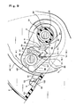
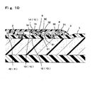
- the closing part 9 closes the inlet 32, the guiding surface 91 guides the turning operation of the guide piece 81 as the hub 82 is turned, and under a state in which the stopper 5 faces against the passing notch 102, the closing part 9 releases the inlet 32 to release the guide of the guide piece 81 (refer to Figs. 5 , 6 , 9 and 10 ).
- the hub 82 is fitted to the notch 31.
- the guide piece 81 pushes against the pushing surface 92, thereby the closing part 9 slides in a guide releasing direction to release the inlet 32 and it closes by a biasing force in concurrent with operation in which the hub 82 is fitted to the notch 31
- the operating lever 93 is set at such a position as one in which it is exposed to be enabled to operate at the full-opened upper limit position of the shield 1 (refer to Fig. 9 ).
- Reference numeral 34 denotes a leaf spring which is integrally arranged at the engagement male member B so as to bias the stopper 5 in the aforesaid direction.
- the leaf spring 34 pushes against a pushing wall 92 integrally arranged at the connecting plate 51 behind the closing part 9 and the stopper 5 is biased by the biasing force in a direction moving away from the passing notch 102.
- Biasing force of the leaf spring 34 biases the stopper 5 in such a direction as one in which the closing part 9 always closes the inlet 32.
- Sliding structure of the stopper 5 is made such that a protuberance 94 integrally formed with the engagement male member B and formed along a sliding direction of the stopper 5 is held by a protuberance 95 integrally formed at the location opposing against the protuberance 94 of the connecting plate 51 and by the operating lever 93 to cause the stopper 5 to be slid (refer to Figs. 2 , 4 , 7 and 11 ).
- connecting plate 51 is held at its front side and rear side to cause the stopper 5 and the engagement male member B to be integrally engaged to each other.
- the end part of the raised portion of the protuberance 95 and the pressing plate 96 for pressing the front surface side of the connecting plate 51 are integrally arranged at the base part of the protuberance 94 and in turn the extremity end side of the leaf spring 34 is formed with a pressing protuberance 98 for pressing the rear surface side of the connecting plate 51 while being engaged with the engagement notch 97 arranged at the lower end of the pressing wall 92, the front side and the rear side of the connecting plate 51 are held by these pressing plate 96 and pressing protuberance 98 to cause the stopper 5 to be integrally engaged with the engagement male member B (refer to Figs. 2 and 4 ).
- the stopper 5 is slidably and integrally engaged with the engagement male member B to become one unit, so that its installing work to the helmet A becomes quite easy.
- Reference numeral 10 denotes a holding part for keeping opposed states of both stopper 5 and passing notch 102 when the stopper 5 slides in the passing notch 102 and for holding the released state of the closing part 9.
- the holding part 10 is constituted by a deformed plate 12 constituting one of the holding parts 10 and integrally arranged at the connecting plate 51 with resiliency; a hook protuberance 13 integrally projected outside the extremity end of the deformed plate 12; and a hook stopper 14 constituting the other of the holding parts 10, arranged at the fixing part 2 and having the hook protuberance 13 engaged with it.
- the hook protuberance 13 is comprised of a hook surface 15 hooked with the hook stopper 14 at its extremity end, and a slant surface 16 cooperatively arranged at the hook surface 15 and inclined at its extremity end and toward its thick portion.
- the hook stopper 14 is set to have such a length as one to cause the hook protuberance 13 to be hooked when the shield 1 is over the full-opened upper limit position and it is raised into an arcuate shape in concentric with the pivot part 8.
- the stopper 5 is contacted with the engagement protuberance 101, its further turning is restricted and at the same time the operating lever 93 is exposed at the state in which it can be operated and the hook stopper 14 reaches such a position as one in which the hook protuberance 13 can be engaged (refer to Figs. 5 to 8 ).
- the shield 1 is widened outwardly by its own resilient force in concurrent with the removing enabled state, the hub 82 is removed from the notch 31 and the shield 1 is removed (refer to Fig. 14 ).
- the shield 1 In order to fix the shield 1, the shield 1 is positioned at the aforesaid removing-enabled state, the hub 82 is pushed into the notch 31, the guide piece 81 pushes against the pressing surface 92 as described above, the closing part 9 is slid in a guide releasing direction to release the inlet 32.
- the closing part 9 In concurrent with fitting of the hub 82 with the notch 31, the closing part 9 returns back to its original state by the biasing force to close the inlet and then the guiding of the guide piece 81 is started.
- the shield 1 As the shield 1 is turned downwardly from this state, the engagement protuberance 101 moves along the slant surface 53 of the stopper 5 in the same manner as that described in the gazette, the shield 1 widens gradually in an outward direction, the engagement protuberance 101 rides over the stopper 5 and at the same time, the shield 1 returns back to its original state by its own resilient force, thereby it becomes a normal openable or closable turning state shown in Figs. 1 to 4 .
- the present invention can provide the fixing structure for the shield in which the shield fixing or removing operation can be carried out in its improved convenience upon holding the superior effect of the fixing structure proposed in the aforesaid gazette due to the fact that the shield can be removed under normal opening operation performed through operation of the operating part.
- the shield can be turned without releasing and keep on stopping the stopper with a hand of the user by himself or by herself.
- the shield is turned more upward from the full-opened upper limit position, thereby the engagement between the guide piece and the engagement step is released for the first time to enable the guide piece to be removed from the inlet, so that even if the operating part is operated erroneously at the full-opened upper limit position, the shield can not be released only by this operation.
- the held state of the stopper is released automatically, so that even if the stopper is slid erroneously at the full-opened upper limit position and so on, it can be returned rapidly back to a normal shield fixing state.
- engagement male member and the stopper are integrally engaged with each other to accomplish one unit, so that its installing work for the helmet or its decomposing or maintenance work becomes quite easy.
Landscapes
- Helmets And Other Head Coverings (AREA)
- Snaps, Bayonet Connections, Set Pins, And Snap Rings (AREA)
Claims (22)
- Dispositif pour monter une visière destiné à attacher une visière (1) sur un casque (A), le dispositif de fixation de visière comportant deux composants, un composant étant attaché sur chaque côté dudit casque (A) alors que ladite visière (1) s'étend entre les côtés, chacun desdits composants comprenant :un élément d'engagement mâle (B) apte à être raccordé au casque (A), ledit élément d'engagement mâle (B) comportant une butée (5) afin de limiter le mouvement de ladite visière (1) ;un élément d'engagement femelle (C) raccordé de façon amovible à l'élément d'engagement mâle (B), ledit élément d'engagement femelle (C) possédant une section de fixation pour permettre d'attacher lesdits deux composants à ladite visière (1) ;caractérisé par une encoche de passage (102) destinée à s'opposer à ladite butée (5) lorsqu'on fait tourner ladite visière (1) vers une position ouverte à partir d'une position fermée, et à passer au-dessus de ladite butée (5) lorsqu'on fait tourner ladite visière (1) vers une position d'enlèvement afin d'être enlevée dudit casque (A), et
lesdits composants sont positionnés sur des côtés opposés dudit casque (A), chaque extrémité de ladite visière (1) étant attachée au casque au moyen desdits composants de fixation de visière. - Dispositif de fixation de visière, selon la revendication 1:ladite section de fixation comprenant en outre une saillie d'engagement (101) laquelle est engagée de façon coulissante avec ledit élément d'engagement mâle (B).
- Dispositif de fixation de visière, selon la revendication 2 :ledit élément d'engagement femelle (C) possédant une section à pivot (8) ;ladite visière (1) tournant autour de ladite section à pivot (8) lorsqu'on la change d'une position à une autre, et lorsqu'on l'enlève dudit casque (A).
- Dispositif de fixation de visière, selon la revendication 3 :ladite section à pivot (8) comprenant en outre un moyeu (82) et une pièce de guidage (81) ;ledit élément d'engagement mâle (B) comprenant en outre un orifice d'entrée (32) ;ledit moyeu (82) possédant un axe central autour duquel ledit moyeu tourne ;ladite section à pivot (8) étant en engagement rotatif avec ledit élément d'engagement mâle (B) ;cas dans lequel, lorsqu'on fait tourner ladite section à pivot (8) autour dudit moyeu (82) et que ladite pièce de guidage (81) coïncide avec ledit orifice d'entrée (32), ledit élément d'engagement femelle (C) est apte à être enlevé de son engagement avec ledit élément d'engagement mâle (B), ce qui permet par conséquent d'enlever la visière (1) du casque (A).
- Dispositif de fixation de visière, selon la revendication 4 :ladite saillie d'engagement (101) comportant une encoche (31),cas dans lequel ladite butée (5) passe par ladite encoche (102) lorsqu'on enlève ladite visière (1) dudit casque (A).
- Dispositif de fixation de visière, selon la revendication 5 :ladite butée (5) ayant une saillie munie d'une surface verticale et d'une surface inclinée ; etladite butée (5) possédant un levier (93) qui oblige ladite butée (5) à se déplacer quand il est actionné,cas dans lequel ladite saillie de ladite butée (5) passe par ladite encoche (102) lorsqu'on enlève ladite visière (1) dudit casque (A), et aboute contre ladite saillie d'engagement (101) lorsqu'on déplace ladite visière (1) vers une position ouverte.
- Dispositif de fixation de visière, selon la revendication 6 :ledit élément d'engagement mâle (B) possédant une section de support (3) qui est engagée avec ladite section à pivot (8) dudit élément d'engagement femelle (C) ;ladite section de support (3) facilitant la rotation dudit élément d'engagement mâle (B) autour de ladite section à pivot (8) dudit élément d'engagement femelle (C).
- Dispositif de fixation de visière, selon la revendication 7 :ledit moyen d'engagement femelle (C) comprenant en outre une plaque de guidage (42) dont un bord cranté comporte une pluralité d'encoches de forme arquée ; etledit moyen d'engagement mâle (B) comprenant en outre une pièce élastique (41) qui comporte au moins un bord de forme arquée,cas dans lequel ladite pièce élastique (41) s'engage par accouplement avec ledit bord cranté de ladite plaque de guidage (42) lorsqu'on fait tourner ladite visière (1) d'une position à une autre position, etladite pièce élastique (41) génère une force élastique lorsque ladite section de support (3) est engagée avec ladite section à pivot (8), ce qui fait que la surface circonférentielle externe de ladite pièce élastique (41) est poussée contre ladite section d'engagement (421).
- Dispositif de fixation de visière, selon la revendication 1, caractérisé en ce que lesdits composants sont des images inverses les uns par rapport aux autres.
- Dispositif de fixation de visière, selon la revendication 1, caractérisé en ce que les éléments d'engagement femelle (C) constituent une base pour la rotation de ladite visière (1) et ladite visière (1) est apte à être soumise à une rotation entre une position fermée et une position ouverte et est également apte à être enlevée dudit casque (A).
- Dispositif de fixation de visière, selon la revendication 1, caractérisé en ce que :l'élément d'engagement femelle (C) possède une section de fixation (2) destinée à être attachée à la visière (1).
- Dispositif de fixation de visière, selon la revendication 11 :ladite section de fixation (2) comprenant en outre une saillie d'engagement laquelle est engagée de façon coulissante avec ledit élément d'engagement mâle (B).
- Dispositif de fixation de visière, selon la revendication 12 :ledit élément d'engagement femelle (C) possédant une section à pivot (8) ;ladite visière (1) tournant autour de ladite section à pivot (8) lorsqu'on la change d'une position à une autre, et lorsqu'on l'enlève dudit casque (A).
- Dispositif de fixation de visière, selon la revendication 13 :ladite section à pivot (8) comprenant en outre un moyeu (82) et une pièce de guidage (81) ;ledit élément d'engagement mâle (B) comprenant en outre un orifice d'entrée (32) ;ledit moyeu (82) possédant un axe central autour duquel ledit moyeu (82) tourne ;ladite section à pivot (8) étant en engagement rotatif avec ledit élément d'engagement mâle (B),cas dans lequel, lorsqu'on fait tourner ladite section à pivot (8) autour dudit moyeu (82) et que ladite pièce de guidage (81) coïncide avec ledit orifice d'entrée (32), ledit élément d'engagement femelle (C) est apte à être enlevé de son engagement avec ledit élément d'engagement mâle (B), ce qui permet par conséquent d'enlever la visière (1) du casque (A).
- Dispositif de fixation de visière, selon la revendication 14 :ladite saillie d'engagement (101) comportant une encoche (31),cas dans lequel ladite butée (5) passe par ladite encoche (31) lorsqu'on enlève ladite visière (1) dudit casque (A).
- Dispositif de fixation de visière, selon la revendication 15:ladite butée (5) ayant une saillie munie d'une surface verticale et d'une surface inclinée ; etladite butée (5) possédant un levier (93) qui oblige ladite butée (5) à se déplacer quand il est actionné,cas dans lequel ladite saillie de ladite butée (5) passe par ladite encoche (31) lorsqu'on enlève ladite visière (1) dudit casque (A), et aboute contre ladite saillie d'engagement (101) lorsqu'on déplace ladite visière (1) vers une position ouverte.
- Dispositif de fixation de visière, selon la revendication 16 :ledit élément d'engagement mâle (B) possédant une section de support (3) qui est engagée avec ladite section à pivot (8) dudit élément d'engagement femelle (C) ;ladite section de support (3) facilitant la rotation dudit élément d'engagement mâle (B) autour de ladite section à pivot (8) dudit élément d'engagement femelle (C).
- Dispositif de fixation de visière, selon la revendication 17 :ledit moyen d'engagement femelle (C) comprenant en outre une plaque de guidage (42) dont un bord cranté comporte une pluralité d'encoches de forme arquée ; etledit moyen d'engagement mâle (B) comprenant en outre une pièce élastique (41) qui comporte au moins un bord de forme arquée,cas dans lequel ladite pièce élastique (41) s'engage par accouplement avec ledit bord cranté de ladite plaque de guidage (42) lorsqu'on fait tourner ladite visière (1) d'une position à une autre position, etladite pièce élastique (41) génère une force élastique lorsque ladite section de support (3) est engagée avec ladite section à pivot (8), ce qui fait que la surface circonférentielle externe de ladite pièce élastique (41) est poussée contre ladite section d'engagement (421).
- Dispositif de fixation de visière, selon la revendication 1, caractérisé en ce que le dispositif est installé au niveau d'une surface frontale du corps principal du casque (A).
- Dispositif de fixation de visière, selon la revendication 19, caractérisé en ce que seulement au moment où les saillies d'engagement (101) entrent en contact avec les butées (5) au niveau de la position de limite supérieure entièrement ouverte de la visière (1) et que les saillies d'engagement (101) passent au-dessus des butées (5), les pièces de guidage (81) des moyeux (2) installées sur les sections de fixation de la visière (1) seront libérées de leur engagement avec les gradins d'engagement ménagés dans les encoches de support du moyeu (82) des éléments d'engagement mâles (B) disposés dans les côtés droit et gauche du casque (A) et peuvent être enlevés de l'orifice d'entrée formé au niveau de l'encoche (31) afin de monter ou d'enlever les pièces de guidage (81).
- Dispositif de fixation de visière, selon la revendication 20, caractérisé en ce que les saillies d'engagement (101) sont formées avec les encoches de passage (102) ayant une taille dans laquelle les butées (5) peuvent passer, les butées (5) étant engagées de façon intégrale avec les éléments d'engagement mâles (B) de manière coulissante, et soumises à une poussée suivant une direction telle qu'elles sont toujours enlevées des encoches (31) de sorte qu'elles coïncident avec les encoches de passage (102) et en sont enlevées.
- Dispositif de fixation de visière, selon la revendication 21, caractérisé en ce que les butées (5) sont maintenues par les sections de retenue (10) lesquelles maintiennent les positions coïncidant avec les encoches de passage (102) au-dessus de la position de limite supérieure entièrement ouverte de la visière (1) en vertu de l'actionnement de la section fonctionnelle destinée à être coulissée contre la force de poussée à la position de limite supérieure entièrement ouverte de la visière (1), l'état engagé avec les saillies d'engagement (101) sera libéré pour qu'il soit possible de faire tourner la visière (1) vers le haut à partir de la position de limite supérieure entièrement ouverte jusqu'à la position d'autorisation de libération et, par ailleurs, lorsque la visière (1) est déplacée vers le haut jusqu'à la position d'autorisation de libération et qu'elle est enlevée de celle-ci, et lorsque la visière (1) est abaissée à partir de la position de limite supérieure entièrement ouverte du fait qu'elle n'est pas soumise à l'action de déplacement vers le haut jusqu'à la position d'autorisation de libération, les butées (5) seront libérées des sections de retenue (10) et seront remises à un état initial par ladite force de poussée.
Applications Claiming Priority (2)
| Application Number | Priority Date | Filing Date | Title |
|---|---|---|---|
| JP2001096692 | 2001-03-29 | ||
| JP2001096692A JP3549490B2 (ja) | 2001-03-29 | 2001-03-29 | ヘルメットにおけるシールドの取付構造 |
Publications (3)
| Publication Number | Publication Date |
|---|---|
| EP1245165A2 EP1245165A2 (fr) | 2002-10-02 |
| EP1245165A3 EP1245165A3 (fr) | 2005-08-24 |
| EP1245165B1 true EP1245165B1 (fr) | 2008-05-14 |
Family
ID=18950580
Family Applications (1)
| Application Number | Title | Priority Date | Filing Date |
|---|---|---|---|
| EP01309088A Expired - Lifetime EP1245165B1 (fr) | 2001-03-29 | 2001-10-26 | Dispositif pour monter une visière sur un casque |
Country Status (8)
| Country | Link |
|---|---|
| US (2) | US20020138897A1 (fr) |
| EP (1) | EP1245165B1 (fr) |
| JP (1) | JP3549490B2 (fr) |
| KR (1) | KR100733859B1 (fr) |
| CN (1) | CN1195428C (fr) |
| AT (1) | ATE394954T1 (fr) |
| DE (1) | DE60133990D1 (fr) |
| TW (1) | TWI228396B (fr) |
Cited By (1)
| Publication number | Priority date | Publication date | Assignee | Title |
|---|---|---|---|---|
| US11213089B2 (en) | 2019-06-04 | 2022-01-04 | Msa Technology, Llc | Protective helmet with face protection shield and linkage mechanism |
Families Citing this family (32)
| Publication number | Priority date | Publication date | Assignee | Title |
|---|---|---|---|---|
| USD495838S1 (en) | 2003-07-10 | 2004-09-07 | Arai Helmet (Europe) B.V. | Helmet |
| USD498563S1 (en) | 2003-07-11 | 2004-11-16 | Bombardier Recreational Products Inc. | Combined helmet eye shield and visor |
| KR100568946B1 (ko) * | 2004-11-25 | 2006-04-10 | 주식회사 홍진에이치제이씨 | 헬멧용 실드 결합장치 |
| USD547007S1 (en) * | 2005-02-28 | 2007-07-17 | Schuberth Werk Gmbh | Commando helmet |
| TWM273977U (en) * | 2005-04-13 | 2005-09-01 | Bing-Jang Ye | Union structure of helmet lens and helmet body |
| KR100659171B1 (ko) * | 2005-12-15 | 2006-12-19 | 주식회사 홍진에이치제이씨 | 헬멧용 턱 보호대의 개폐장치 |
| JP4895647B2 (ja) * | 2006-03-17 | 2012-03-14 | 株式会社Shoei | ヘルメット |
| US8069499B2 (en) * | 2006-05-15 | 2011-12-06 | Shoei Co., Ltd. | Helmet shield attaching mechanism, and helmet attached with the same |
| KR100750720B1 (ko) * | 2006-09-21 | 2007-08-22 | 주식회사 기도스포츠 | 헬멧 |
| JP4976153B2 (ja) * | 2007-02-06 | 2012-07-18 | 株式会社Shoei | ヘルメットサイズの調整方法 |
| JP5041906B2 (ja) * | 2007-08-07 | 2012-10-03 | 株式会社Shoei | ヘルメット |
| US8166576B2 (en) * | 2008-05-21 | 2012-05-01 | Katoh Electrical Machinery Co., Ltd. | Opening/closing device and helmet having the same |
| NZ568990A (en) * | 2008-06-06 | 2011-02-25 | Pacific Helmets Nz Ltd | Hinge system/visor attachment |
| KR101052092B1 (ko) | 2008-11-17 | 2011-07-27 | 주식회사 바이온셀 | 생약재추출물이 함유된 화장료 조성물 및 그 추출방법 |
| USD640010S1 (en) * | 2009-05-27 | 2011-06-14 | Mat Global Solutions, S.L. | Motorcycle helmet |
| WO2012044898A1 (fr) | 2010-10-01 | 2012-04-05 | HaberVision LLC | Systèmes de lunetterie de protection et procédés pour renforcer la vision |
| USD682479S1 (en) * | 2011-04-28 | 2013-05-14 | Msa Gallet | Fireman helmet |
| WO2013047930A1 (fr) * | 2011-09-30 | 2013-04-04 | 주식회사 홍진에이치제이씨 | Dispositif d'accouplement pour protecteur facial et casque le comprenant |
| ITVR20120022A1 (it) * | 2012-02-20 | 2013-08-21 | Agv Spa | Dispositivo di movimentazione per un casco per muovere un primo elemento del casco rispetto ad un secondo elemento del casco. |
| USD696465S1 (en) * | 2012-08-22 | 2013-12-24 | Hjc Corp. | Helmet |
| USD696464S1 (en) * | 2012-08-22 | 2013-12-24 | Hjc Corp. | Helmet |
| USD774257S1 (en) * | 2015-02-11 | 2016-12-13 | Joey LaRocque | Helmet |
| US11419381B2 (en) * | 2015-05-19 | 2022-08-23 | Maurício Paranhos Torres | Cranial protection cell |
| FR3046912A1 (fr) * | 2016-01-22 | 2017-07-28 | Salomon Sas | Systeme d'accroche d'une visiere sur un casque de protection et casque muni d'une visiere assemblee avec un tel systeme d'accroche |
| AU201617063S (en) * | 2016-06-22 | 2017-01-12 | Locatelli S P A | Helmet |
| JP1643008S (fr) * | 2019-02-07 | 2019-10-07 | ||
| JP7168480B2 (ja) * | 2019-02-08 | 2022-11-09 | 株式会社Shoei | バイザーのロック機構及びヘルメット |
| CN110754730A (zh) * | 2019-11-15 | 2020-02-07 | 徐州旭升车辆制造有限公司 | 一种井下应急安全帽 |
| USD1038529S1 (en) * | 2021-11-19 | 2024-08-06 | Hjc Corp. | Helmet |
| USD1038528S1 (en) * | 2021-11-19 | 2024-08-06 | Hjc Corp. | Helmet |
| USD1064418S1 (en) * | 2022-05-24 | 2025-02-25 | HJC Corporation | Helmet |
| USD1054632S1 (en) * | 2023-08-03 | 2024-12-17 | Shark | Helmet for motorcyclists |
Family Cites Families (12)
| Publication number | Priority date | Publication date | Assignee | Title |
|---|---|---|---|---|
| JPH0660444B2 (ja) * | 1987-06-09 | 1994-08-10 | 理夫 新井 | ヘルメットにおけるシールドの取付構造 |
| JPH01207412A (ja) * | 1987-10-26 | 1989-08-21 | Shoei Kako Kk | ヘルメットのシールド装置 |
| US5095551A (en) * | 1990-06-18 | 1992-03-17 | Chin Chen L S | Motorcycle helmet angle-adjustable wind visor mounting structure |
| JPH0635682B2 (ja) * | 1990-08-15 | 1994-05-11 | 昭栄化工株式会社 | ヘルメットのシールド板取付構造 |
| JPH04126812A (ja) * | 1990-09-12 | 1992-04-27 | Dainippon Ink & Chem Inc | 乗車用ヘルメット |
| JPH0621369B2 (ja) * | 1991-02-04 | 1994-03-23 | 昭栄化工株式会社 | ヘルメットにおけるシールド板開閉制御装置 |
| JPH0621370B2 (ja) * | 1991-05-31 | 1994-03-23 | 昭栄化工株式会社 | ヘルメットにおけるシールド板取付構造 |
| JPH0699846B2 (ja) * | 1992-09-03 | 1994-12-07 | 株式会社アライヘルメット | ヘルメットにおけるシールドの取付構造 |
| JPH086202B2 (ja) * | 1993-06-18 | 1996-01-24 | 昭栄化工株式会社 | ヘルメットにおけるシールド板取付構造 |
| JP3891623B2 (ja) * | 1996-12-17 | 2007-03-14 | 株式会社Shoei | ヘルメットのシールド板取付け機構 |
| CA2289371A1 (fr) * | 1998-11-13 | 2000-05-13 | Hong Jin Crown Corporation | Raccord d'ecran facial pour casque |
| US6301721B1 (en) * | 1999-03-12 | 2001-10-16 | Michio Arai | Shield fixing structure in helmet |
-
2001
- 2001-03-29 JP JP2001096692A patent/JP3549490B2/ja not_active Expired - Fee Related
- 2001-05-25 KR KR1020010028944A patent/KR100733859B1/ko not_active Expired - Fee Related
- 2001-06-07 TW TW090113798A patent/TWI228396B/zh not_active IP Right Cessation
- 2001-10-26 DE DE60133990T patent/DE60133990D1/de not_active Expired - Lifetime
- 2001-10-26 AT AT01309088T patent/ATE394954T1/de not_active IP Right Cessation
- 2001-10-26 EP EP01309088A patent/EP1245165B1/fr not_active Expired - Lifetime
- 2001-11-13 US US09/987,018 patent/US20020138897A1/en not_active Abandoned
-
2002
- 2002-01-30 CN CNB021032327A patent/CN1195428C/zh not_active Expired - Fee Related
-
2003
- 2003-06-12 US US10/459,441 patent/US6711753B2/en not_active Expired - Lifetime
Cited By (1)
| Publication number | Priority date | Publication date | Assignee | Title |
|---|---|---|---|---|
| US11213089B2 (en) | 2019-06-04 | 2022-01-04 | Msa Technology, Llc | Protective helmet with face protection shield and linkage mechanism |
Also Published As
| Publication number | Publication date |
|---|---|
| EP1245165A3 (fr) | 2005-08-24 |
| CN1195428C (zh) | 2005-04-06 |
| CN1378802A (zh) | 2002-11-13 |
| US20030196255A1 (en) | 2003-10-23 |
| TWI228396B (en) | 2005-03-01 |
| JP3549490B2 (ja) | 2004-08-04 |
| ATE394954T1 (de) | 2008-05-15 |
| US20020138897A1 (en) | 2002-10-03 |
| DE60133990D1 (de) | 2008-06-26 |
| KR100733859B1 (ko) | 2007-06-29 |
| JP2002294511A (ja) | 2002-10-09 |
| US6711753B2 (en) | 2004-03-30 |
| KR20020076993A (ko) | 2002-10-11 |
| EP1245165A2 (fr) | 2002-10-02 |
Similar Documents
| Publication | Publication Date | Title |
|---|---|---|
| US6711753B2 (en) | Shield fixing structure in helmet | |
| EP0629357B1 (fr) | Dispositif pour monter une visière sur un casque | |
| US4748696A (en) | Safety helmet | |
| EP0294676B1 (fr) | Dispositif pour monter une visière sur un casque de protection | |
| US7376981B2 (en) | Helmet | |
| US4866792A (en) | Shield mounting assembly for a safety helmet | |
| JP2668322B2 (ja) | 乗車用ヘルメット | |
| US6260213B1 (en) | Shield connector for helmet | |
| JPH04257304A (ja) | ヘルメットにおけるシールド板開閉制御装置 | |
| JPH0689483B2 (ja) | ヘルメットにおけるシールドの取付構造 | |
| US6301721B1 (en) | Shield fixing structure in helmet | |
| US20160286890A1 (en) | Helmet and visor assembly | |
| US6442766B1 (en) | Shield supporting structure in helmet | |
| JP2702397B2 (ja) | ヘルメットのシールド取付装置 | |
| EP2063728B1 (fr) | Casque de protection pourvu d'une visiere renfoncee affleurante comprenant une partie avant de mentonniere-visiere inclinable | |
| EP1000558A2 (fr) | Dispositif pour monter une visière sur un casque | |
| GB2087220A (en) | Device for adjusting the opening of the visors in crash helmets for motorcyclists and the like | |
| JP2810657B2 (ja) | ヘルメットのシールド取付装置 | |
| JPH072575Y2 (ja) | ヘルメットにおけるシールドのロック機構 | |
| CA2925650C (fr) | Ensemble de casque et de visiere | |
| JP3395888B2 (ja) | ヘルメットのシールド取付構造 | |
| JPH0461084B2 (fr) | ||
| JPH0735601B2 (ja) | ヘルメットにおけるシールド板取付構造 | |
| JPH01183508A (ja) | シールド取付装置 | |
| JPS62141108A (ja) | ヘルメツトのシ−ルド板装置 |
Legal Events
| Date | Code | Title | Description |
|---|---|---|---|
| PUAI | Public reference made under article 153(3) epc to a published international application that has entered the european phase |
Free format text: ORIGINAL CODE: 0009012 |
|
| AK | Designated contracting states |
Kind code of ref document: A2 Designated state(s): AT BE CH CY DE DK ES FI FR GB GR IE IT LI LU MC NL PT SE TR |
|
| AX | Request for extension of the european patent |
Free format text: AL;LT;LV;MK;RO;SI |
|
| PUAL | Search report despatched |
Free format text: ORIGINAL CODE: 0009013 |
|
| AK | Designated contracting states |
Kind code of ref document: A3 Designated state(s): AT BE CH CY DE DK ES FI FR GB GR IE IT LI LU MC NL PT SE TR |
|
| AX | Request for extension of the european patent |
Extension state: AL LT LV MK RO SI |
|
| 17P | Request for examination filed |
Effective date: 20060220 |
|
| AKX | Designation fees paid |
Designated state(s): AT BE CH CY DE DK ES FI FR GB GR IE IT LI LU MC NL PT SE TR |
|
| 17Q | First examination report despatched |
Effective date: 20070213 |
|
| GRAP | Despatch of communication of intention to grant a patent |
Free format text: ORIGINAL CODE: EPIDOSNIGR1 |
|
| GRAS | Grant fee paid |
Free format text: ORIGINAL CODE: EPIDOSNIGR3 |
|
| GRAA | (expected) grant |
Free format text: ORIGINAL CODE: 0009210 |
|
| AK | Designated contracting states |
Kind code of ref document: B1 Designated state(s): AT BE CH CY DE DK ES FI FR GB GR IE IT LI LU MC NL PT SE TR |
|
| REG | Reference to a national code |
Ref country code: GB Ref legal event code: FG4D |
|
| REG | Reference to a national code |
Ref country code: CH Ref legal event code: NV Representative=s name: ABREMA AGENCE BREVET ET MARQUES, GANGUILLET Ref country code: CH Ref legal event code: EP |
|
| REG | Reference to a national code |
Ref country code: IE Ref legal event code: FG4D Free format text: LANGUAGE OF EP DOCUMENT: FRENCH |
|
| REF | Corresponds to: |
Ref document number: 60133990 Country of ref document: DE Date of ref document: 20080626 Kind code of ref document: P |
|
| REG | Reference to a national code |
Ref country code: SE Ref legal event code: TRGR |
|
| PG25 | Lapsed in a contracting state [announced via postgrant information from national office to epo] |
Ref country code: FI Free format text: LAPSE BECAUSE OF FAILURE TO SUBMIT A TRANSLATION OF THE DESCRIPTION OR TO PAY THE FEE WITHIN THE PRESCRIBED TIME-LIMIT Effective date: 20080514 Ref country code: ES Free format text: LAPSE BECAUSE OF FAILURE TO SUBMIT A TRANSLATION OF THE DESCRIPTION OR TO PAY THE FEE WITHIN THE PRESCRIBED TIME-LIMIT Effective date: 20080825 |
|
| PG25 | Lapsed in a contracting state [announced via postgrant information from national office to epo] |
Ref country code: AT Free format text: LAPSE BECAUSE OF FAILURE TO SUBMIT A TRANSLATION OF THE DESCRIPTION OR TO PAY THE FEE WITHIN THE PRESCRIBED TIME-LIMIT Effective date: 20080514 |
|
| PG25 | Lapsed in a contracting state [announced via postgrant information from national office to epo] |
Ref country code: PT Free format text: LAPSE BECAUSE OF FAILURE TO SUBMIT A TRANSLATION OF THE DESCRIPTION OR TO PAY THE FEE WITHIN THE PRESCRIBED TIME-LIMIT Effective date: 20081014 Ref country code: DK Free format text: LAPSE BECAUSE OF FAILURE TO SUBMIT A TRANSLATION OF THE DESCRIPTION OR TO PAY THE FEE WITHIN THE PRESCRIBED TIME-LIMIT Effective date: 20080514 |
|
| PLBE | No opposition filed within time limit |
Free format text: ORIGINAL CODE: 0009261 |
|
| STAA | Information on the status of an ep patent application or granted ep patent |
Free format text: STATUS: NO OPPOSITION FILED WITHIN TIME LIMIT |
|
| 26N | No opposition filed |
Effective date: 20090217 |
|
| PG25 | Lapsed in a contracting state [announced via postgrant information from national office to epo] |
Ref country code: MC Free format text: LAPSE BECAUSE OF NON-PAYMENT OF DUE FEES Effective date: 20081031 |
|
| REG | Reference to a national code |
Ref country code: IE Ref legal event code: MM4A |
|
| PG25 | Lapsed in a contracting state [announced via postgrant information from national office to epo] |
Ref country code: IE Free format text: LAPSE BECAUSE OF NON-PAYMENT OF DUE FEES Effective date: 20081026 |
|
| PG25 | Lapsed in a contracting state [announced via postgrant information from national office to epo] |
Ref country code: LU Free format text: LAPSE BECAUSE OF NON-PAYMENT OF DUE FEES Effective date: 20081026 Ref country code: CY Free format text: LAPSE BECAUSE OF FAILURE TO SUBMIT A TRANSLATION OF THE DESCRIPTION OR TO PAY THE FEE WITHIN THE PRESCRIBED TIME-LIMIT Effective date: 20080514 |
|
| PG25 | Lapsed in a contracting state [announced via postgrant information from national office to epo] |
Ref country code: TR Free format text: LAPSE BECAUSE OF FAILURE TO SUBMIT A TRANSLATION OF THE DESCRIPTION OR TO PAY THE FEE WITHIN THE PRESCRIBED TIME-LIMIT Effective date: 20080514 |
|
| PG25 | Lapsed in a contracting state [announced via postgrant information from national office to epo] |
Ref country code: GR Free format text: LAPSE BECAUSE OF FAILURE TO SUBMIT A TRANSLATION OF THE DESCRIPTION OR TO PAY THE FEE WITHIN THE PRESCRIBED TIME-LIMIT Effective date: 20080815 |
|
| REG | Reference to a national code |
Ref country code: DE Ref legal event code: R082 Ref document number: 60133990 Country of ref document: DE Representative=s name: MAI DOERR BESIER EUROPEAN PATENT ATTORNEYS - E, DE Ref country code: DE Ref legal event code: R082 Ref document number: 60133990 Country of ref document: DE Representative=s name: MAI DOERR BESIER PATENTANWAELTE, DE |
|
| REG | Reference to a national code |
Ref country code: FR Ref legal event code: PLFP Year of fee payment: 15 |
|
| PGFP | Annual fee paid to national office [announced via postgrant information from national office to epo] |
Ref country code: CH Payment date: 20151021 Year of fee payment: 15 |
|
| PGFP | Annual fee paid to national office [announced via postgrant information from national office to epo] |
Ref country code: BE Payment date: 20151019 Year of fee payment: 15 Ref country code: SE Payment date: 20151021 Year of fee payment: 15 Ref country code: NL Payment date: 20151021 Year of fee payment: 15 |
|
| REG | Reference to a national code |
Ref country code: FR Ref legal event code: PLFP Year of fee payment: 16 |
|
| PG25 | Lapsed in a contracting state [announced via postgrant information from national office to epo] |
Ref country code: BE Free format text: LAPSE BECAUSE OF NON-PAYMENT OF DUE FEES Effective date: 20161031 |
|
| REG | Reference to a national code |
Ref country code: CH Ref legal event code: PL |
|
| REG | Reference to a national code |
Ref country code: NL Ref legal event code: MM Effective date: 20161101 |
|
| PG25 | Lapsed in a contracting state [announced via postgrant information from national office to epo] |
Ref country code: CH Free format text: LAPSE BECAUSE OF NON-PAYMENT OF DUE FEES Effective date: 20161031 Ref country code: LI Free format text: LAPSE BECAUSE OF NON-PAYMENT OF DUE FEES Effective date: 20161031 |
|
| PG25 | Lapsed in a contracting state [announced via postgrant information from national office to epo] |
Ref country code: NL Free format text: LAPSE BECAUSE OF NON-PAYMENT OF DUE FEES Effective date: 20161101 Ref country code: SE Free format text: LAPSE BECAUSE OF NON-PAYMENT OF DUE FEES Effective date: 20161027 |
|
| REG | Reference to a national code |
Ref country code: FR Ref legal event code: PLFP Year of fee payment: 17 |
|
| REG | Reference to a national code |
Ref country code: BE Ref legal event code: MM Effective date: 20161031 |
|
| PGFP | Annual fee paid to national office [announced via postgrant information from national office to epo] |
Ref country code: DE Payment date: 20171019 Year of fee payment: 17 |
|
| PGFP | Annual fee paid to national office [announced via postgrant information from national office to epo] |
Ref country code: GB Payment date: 20171019 Year of fee payment: 17 Ref country code: IT Payment date: 20171023 Year of fee payment: 17 |
|
| REG | Reference to a national code |
Ref country code: FR Ref legal event code: PLFP Year of fee payment: 18 |
|
| PGFP | Annual fee paid to national office [announced via postgrant information from national office to epo] |
Ref country code: FR Payment date: 20181022 Year of fee payment: 18 |
|
| REG | Reference to a national code |
Ref country code: DE Ref legal event code: R119 Ref document number: 60133990 Country of ref document: DE |
|
| GBPC | Gb: european patent ceased through non-payment of renewal fee |
Effective date: 20181026 |
|
| PG25 | Lapsed in a contracting state [announced via postgrant information from national office to epo] |
Ref country code: DE Free format text: LAPSE BECAUSE OF NON-PAYMENT OF DUE FEES Effective date: 20190501 |
|
| PG25 | Lapsed in a contracting state [announced via postgrant information from national office to epo] |
Ref country code: GB Free format text: LAPSE BECAUSE OF NON-PAYMENT OF DUE FEES Effective date: 20181026 Ref country code: IT Free format text: LAPSE BECAUSE OF NON-PAYMENT OF DUE FEES Effective date: 20181026 |
|
| PG25 | Lapsed in a contracting state [announced via postgrant information from national office to epo] |
Ref country code: FR Free format text: LAPSE BECAUSE OF NON-PAYMENT OF DUE FEES Effective date: 20191031 |