EP1245456A1 - Aufpralldämpfer - Google Patents
Aufpralldämpfer Download PDFInfo
- Publication number
- EP1245456A1 EP1245456A1 EP02005951A EP02005951A EP1245456A1 EP 1245456 A1 EP1245456 A1 EP 1245456A1 EP 02005951 A EP02005951 A EP 02005951A EP 02005951 A EP02005951 A EP 02005951A EP 1245456 A1 EP1245456 A1 EP 1245456A1
- Authority
- EP
- European Patent Office
- Prior art keywords
- hollow body
- fastening
- fastening surface
- jacket
- impact
- Prior art date
- Legal status (The legal status is an assumption and is not a legal conclusion. Google has not performed a legal analysis and makes no representation as to the accuracy of the status listed.)
- Granted
Links
Images


Classifications
-
- B—PERFORMING OPERATIONS; TRANSPORTING
- B60—VEHICLES IN GENERAL
- B60R—VEHICLES, VEHICLE FITTINGS, OR VEHICLE PARTS, NOT OTHERWISE PROVIDED FOR
- B60R19/00—Wheel guards; Radiator guards, e.g. grilles; Obstruction removers; Fittings damping bouncing force in collisions
- B60R19/02—Bumpers, i.e. impact receiving or absorbing members for protecting vehicles or fending off blows from other vehicles or objects
- B60R19/24—Arrangements for mounting bumpers on vehicles
- B60R19/26—Arrangements for mounting bumpers on vehicles comprising yieldable mounting means
- B60R19/34—Arrangements for mounting bumpers on vehicles comprising yieldable mounting means destroyed upon impact, e.g. one-shot type
-
- F—MECHANICAL ENGINEERING; LIGHTING; HEATING; WEAPONS; BLASTING
- F16—ENGINEERING ELEMENTS AND UNITS; GENERAL MEASURES FOR PRODUCING AND MAINTAINING EFFECTIVE FUNCTIONING OF MACHINES OR INSTALLATIONS; THERMAL INSULATION IN GENERAL
- F16F—SPRINGS; SHOCK-ABSORBERS; MEANS FOR DAMPING VIBRATION
- F16F7/00—Vibration-dampers; Shock-absorbers
- F16F7/12—Vibration-dampers; Shock-absorbers using plastic deformation of members
-
- B—PERFORMING OPERATIONS; TRANSPORTING
- B60—VEHICLES IN GENERAL
- B60R—VEHICLES, VEHICLE FITTINGS, OR VEHICLE PARTS, NOT OTHERWISE PROVIDED FOR
- B60R21/00—Arrangements or fittings on vehicles for protecting or preventing injuries to occupants or pedestrians in case of accidents or other traffic risks
- B60R2021/0002—Type of accident
- B60R2021/0023—Offset collision
Definitions
- the invention relates to an impact damper for motor vehicles for energy consumption in the event of a collision between the motor vehicle and an obstacle Features of the preamble of claim 1 or the subordinate Claim 4.
- Impact absorbers of the type in question serve to protect the occupants of a motor vehicle in a collision, in particular in a front, rear or Side collision in that it is the one released in such a collision Absorb energy as much as possible through deformation and to the Do not pass on the passenger compartment or only pass it on to a significantly reduced extent.
- Such impact dampers are primarily used between those connected to the passenger compartment Vehicle side members and the transverse bumper side Cross beams, the so-called bumper cross beams.
- the primary task of the bumper cross member is in the event of a collision a train connection between the right and left side of the vehicle body to ensure optimal occupant protection.
- Impact dampers between the vehicle side members and the bumper cross members must therefore have a tensile connection between the involved carriers as well as the desired energy consumption by deformation.
- impact dampers are entirely considerable demands on material and design.
- Impact dampers are usually made of metal, especially steel, if necessary also made of aluminum, magnesium or corresponding alloys. Very different types of steel, including high-strength steels in the corresponding Shapes are often used here.
- Impact dampers for motor vehicles for energy absorption are also for side collisions deployed within the structures, commonly known as side impact protection be designated.
- the area of the B-pillar and if necessary the C-pillar could be interesting for the arrangement of the impact absorber.
- impact dampers of the type in question are also inside the passenger compartment can be used, for example as a support arrangement for knee pads.
- the force-displacement curve is essential for the function and effect of an impact damper vital.
- the beginning of deformation is of considerable importance.
- very complex movements of the bumper cross member on which is taken into account when designing the impact damper should be.
- the fastening surfaces are parallel to one another aligned, which is often the case, the adaptation to the mostly in a complicated manner, the curved shape of the bumper cross member, the strak, done in another way.
- the Bumper cross member has different cross sections or that wedge-shaped / arc-shaped Compensating elements between the bumper cross member and the impact damper inserted and welded or screwed (EP 0 718 157 A1, EP 0 718 158 A1).
- the angular position between the bumper cross member and the front surface of the impact absorber changes in a laterally offset front collision, that the bumper crossmember is initially strongly depressed in the middle is and only then a substantially uniform deformation over the full width of the impact area in the longitudinal direction.
- It can Known impact absorbers that occur transversely to the longitudinal direction force component occurring so large, especially at the beginning of the front collision is that the bumper cross member tears off the impact damper or the impact damper kinked sideways. The impact damper thus loses at Beginning of the front collision its effect, which only afterwards to protect the passenger compartment.
- the teaching is therefore based on the problem of an impact damper for motor vehicles to indicate the properties regarding collision, especially in a laterally offset front collision.
- the arcuate in accordance with the Strak running bumper cross member especially with a laterally offset Front collision on the inside of the motor vehicle body Side that is the first or the most powerful in the event of a collision is deformed in a targeted manner in the longitudinal direction without the main part the impact damper, namely the hollow body as such, already deformed becomes.
- the lead path realized according to the invention it is guaranteed that in a laterally offset front collision initially at an acute angle to the first mounting surface second mounting surface up to parallelism or approximately parallelism aligns with the first mounting surface.
- the total shock absorber So it stops at the beginning of the deformation and its deformation in the longitudinal direction for the purpose of energy absorption only begins when the bumper cross member is particularly stressed, towards the center the area of the motor vehicle body is considerably deformed inwards Has.
- the function of the shock absorber remains with a laterally offset one Front collision preserved, the passenger compartment remains optimally protected.
- the second mounting surface is So the contact surface on the bumper cross member shaped so that the Mating surface on the bumper cross member here without problems in a considerable Angular range can come to the plant.
- the bolt bearing realized here becomes a bearing on a spherical segment or similarly arcuate cap reached. You can easily screw the bumper cross beam here axially or weld. This is of particular importance Teach also the fact that at the foot of the cap in the transition to Hollow body is formed or can be a kink, which is the asymmetrical Buckling while maintaining the hollow body unchanged a laterally offset front collision in a similar manner as previously explained allowed. This asymmetrical buckling or sinking of the cap into the The body of the hollow body as a whole leads to the firm connection of the Bumper cross member with the impact absorber does not tear open, but itself in the event of a laterally offset front collision.
- Impact absorbers are the subject of the subclaims.
- the subclaims are also more preferred in connection with the explanation Embodiments discussed further with reference to the drawing.
- the Impact absorber 1 intended for use in motor vehicles, specifically for Energy consumption when the motor vehicle collides with an obstacle.
- the impact damper 1 can at various points in the body of the Motor vehicle installed and should be the existing in a collision Absorb kinetic energy as much as possible to work it in deformation implement so that the passenger compartment of the vehicle body is affected as little as possible. On the executions the general part of the description may refer to this again become.
- the exemplary embodiment shown describes, just as an example, one Impact absorber 1 using the example of an insert for energy absorption in a Front collision of the motor vehicle with an obstacle, namely used between a front bumper cross member 2 and one in the vehicle longitudinal direction extending vehicle side member connected to the passenger compartment 3 or its end face.
- this vehicle side member 3 only indicated by dashed lines to the installation position of the impact damper 1 to make it easier to understand.
- the is concealing Front of the bumper cross member 2 has been omitted.
- the impact damper 1 regularly consists of a metal, in particular Steel, possibly also made of an aluminum alloy.
- the impact damper 1 shows the impact damper 1 for absorbing energy in the event of a collision of the motor vehicle with an obstacle.
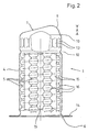
- Fig. 2 in context with Fig. 1, it can be seen that the impact damper 1 is a metal existing, defining a longitudinal direction of the impact damper 1 has cylindrical hollow body 4.
- Preferred embodiments of this cylindrical hollow body 4 are otherwise the subject of older, not previously published Patent applications (100 00 285.4, 100 00 286.2) to which may be referred here to avoid repetitions.
- the Hollow body 4 has a defined compression of the hollow body 4 Deformation beads in the jacket in the longitudinal direction when force is applied 5 on.
- first fastening surface 6 On the hollow body 4 there is an essentially transversely oriented, first fastening surface 6 provided at one end for attachment to a vehicle side member 3 or another structural component of the motor vehicle body.
- second end of the hollow body 4 there is a second fastening surface 7 for fastening the impact damper 1 on a counter surface 8 of the bumper cross member 2 or one other structural component of the motor vehicle body.
- the hollow body 4 is essentially closed at the second end.
- the one located there second fastening surface 7 allows the bumper cross member to be fastened 2 on the hollow body 4 with at an acute angle to the first mounting surface 6 running counter surface 8.
- FIG. 1, 2 and 3 of an inventive Impact absorber 1 is now characterized in that the second mounting surface 7 as an inclined face corresponding to the acute angle of the hollow body 4 is formed, the hollow body 4 is the second fastening surface 7 forming, roof-shaped beveled end portion 9 and approximately below that which is most forward in the longitudinal direction Edge of the second fastening surface 7, in FIG. 1 the one on the top right Edge, on the other hand, set back in the longitudinal direction by a certain distance A, A kink 10 is formed in the jacket of the hollow body. This Kink 10 is designed such that upon initial application of force At this point, a compression takes place here, namely in the essentially without compression of the hollow body 4 in the rest.
- Fig. 3 shows a somewhat more pronounced formation of the kink 10 in one another embodiment.
- the determined distance A corresponds approximately to the distance of the furthest front edge from furthest back Edge of the second fastening surface 7.
- the kink 10 is on the jacket of the Hollow body 4 in the end section 9 extending over a section executed.
- a bead In the embodiment shown in Fig. 3 one can see such a bead, however, also in a modified form on the opposite one Edge.
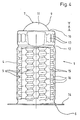
- Fig. 4 shows a further, alternative embodiment of an inventive Impact absorber 1.
- the impact damper 1 here has an arcuate shape, in particular spherical section-shaped cap 11 which the hollow body 4 on closes the second end and forms the second fastening surface 7 there.
- these Cap 11 basically an arbitrary attachment of the counter surface 8th on the hollow body 4, that is to say the function of that in the prior art known pivot pin met, without having its disadvantages.
- connection can be made by welding or by screwing will be realized.
- FIG. 4 Impact absorber 1
- a corresponding one Kink 10 is realized.
- the kink 10 is designed such that at the beginning Applying force at this point initially essentially compresses here otherwise without upsetting the hollow body 4.
- the in Fig. 4 example shows that the kink 10 at the foot of the cap 11 lies within the circumference of the shell of the hollow body 4. This leads the kink 10 so that the cap 11 at the presupposed asymmetrical application of force in the longitudinal direction at the beginning of the deformation overall, so to speak, pressed into the interior of the hollow body 1 becomes. In this way it is particularly useful here the lead path for the function according to the invention is realized.
- the hollow body 4 has an end section 9, which in this case forms the cap 11.
- the end portion 9 of the hollow body 4 from the hollow body 4 in the rest is offset by a completely surrounding bead 12.
- the jacket of the hollow body 4 in the end section 9, namely between the kink 10 and the bead 12, with extending in the longitudinal direction Stiffening ribs 13 is provided.
- the end section 9 of the hollow body 4 overall a relatively stiff in the longitudinal direction, thus only forms a compressible area under high forces into which the roof-shaped beveled end is pressed before the total Hollow body 4 is otherwise in the longitudinal direction, that is, axially compressed.
- the illustrated and preferred exemplary embodiments show, moreover, that, as already known in the prior art, the hollow body 4 for training the first mounting surface 6 an outwardly projecting mounting flange 14 has.
- the hollow body 4 at least three evenly distributed over its circumference and in the longitudinal direction extending web-shaped areas 15 and between adjacent web-shaped regions 15 in the jacket of the hollow body 4 at least three parallel, extending in the circumferential direction and to the interior of the hollow body
- Directional stiffening beads 5 are arranged such that - in axial Direction seen - between adjacent stiffening beads 5 after result in domed areas 16.
- the vaulted ones adjacent on the circumference Areas 16 enclose the in the illustrated embodiment Longitudinal axis of the hollow body 4 helically. An alternative can even with a circular design.
- cylindrical hollow body 4 does not necessarily mean a circular cylindrical design, also other cross-sections, oval, square, polygonal cross-sections are also conceivable if this is in practice proven in experiments.
Landscapes
- Engineering & Computer Science (AREA)
- General Engineering & Computer Science (AREA)
- Mechanical Engineering (AREA)
- Vibration Dampers (AREA)
- Body Structure For Vehicles (AREA)
- Developing Agents For Electrophotography (AREA)
- Lock And Its Accessories (AREA)
- Accessory Devices And Overall Control Thereof (AREA)
Abstract
Description
- Fig. 1
- in einer Prinzipdarstellung einen Ausschnitt eines Stoßfängerquerträgers an einer Kraftfahrzeugkarosserie in Verbindung mit einem Aufpralldämpfer und einem Fahrzeuglängsträger,
- Fig. 2
- ein erstes Ausführungsbeispiel eines erfindungsgemäßen Aufpralldämpfers,
- Fig. 3
- ein zweites Ausführungsbeispiel eines erfindungsgemäßen Aufpralldämpfers,
- Fig. 4
- ein drittes Ausführungsbeispiel eines erfindungsgemäßen Aufpralldämpfers.
Claims (12)
- Aufpralldämpfer für Kraftfahrzeuge zur Energieaufnahme bei einer Kollision des Kraftfahrzeugs mit einem Hindernis,
mit einem aus Metall bestehenden, eine Längsrichtung des Aufpralldämpfers (1) definierenden zylindrischen Hohlkörper (4) mit Verformungssicken (5) im Mantel zur Realisierung einer definierten Stauchung des Hohlkörpers (4) bei Kraftbeaufschlagung in Längsrichtung,
mit einer im wesentlichen quer ausgerichteten, ersten Befestigungsfläche (6) an einem Ende des Hohlkörpers (4) zur Befestigung an einem Fahrzeuglängsträger (3) oder einem anderen Strukturbauelement der Kraftfahrzeugkarosserie,
mit einer zweiten Befestigungsfläche (7) am gegenüberliegenden, zweiten Ende des Hohlkörpers (4) zur Befestigung an einer Gegenfläche (8) eines Stoßfängerquerträgers (2) oder eines anderen Strukturbauelementes der Kraftfahrzeugkarosserie,
wobei der Hohlkörper (4) am zweiten Ende im wesentlichen geschlossen ist und die zweite Befestigungsfläche (7) eine Befestigung des Stoßfängerquerträgers (2) o. dgl. mit in einem spitzen Winkel zur ersten Befestigungsfläche (6) verlaufender Gegenfläche (8) erlaubt,
dadurch gekennzeichnet, daß die zweite Befestigungsfläche (7) an einer entsprechend dem spitzen Winkel geneigten Stirnfläche des Hohlkörpers (4) ausgebildet ist,
daß der Hohlkörper (4) einen die zweite Befestigungsfläche (7) ausbildenden dachförmig abgeschrägten Endabschnitt (9) aufweist und
daß etwa unterhalb des in Längsrichtung am weitesten vorn liegenden Randes der zweiten Befestigungsfläche (7), in Längsrichtung um einen bestimmten Abstand (A) dagegen zurückversetzt, im Mantel des Hohlkörpers (4) eine Knickstelle (10) ausgebildet ist dergestalt, daß bei anfänglicher Kraftbeaufschlagung an dieser Stelle zunächst hier eine Stauchung im wesentlichen ohne Stauchung des Hohlkörpers (4) im übrigen erfolgt. - Aufpralldämpfer nach Anspruch 1, dadurch gekennzeichnet, daß der bestimmte Abstand (A) etwa dem Abstand des am weitesten vorn liegenden Randes von dem am weitesten hinten liegenden Rand der zweiten Befestigungsfläche (7) entspricht.
- Aufpralldämpfer nach Anspruch 1 oder 2 dadurch gekennzeichnet, daß die Knickstelle (10) am Mantel als über einen Abschnitt des Umfangs veraufende Sicke ausgeführt ist.
- Aufpralldämpfer für Kraftfahrzeuge zur Energieaufnahme bei einer Kollision des Kraftfahrzeugs mit einem Hindernis,
mit einem aus Metall bestehenden, eine Längsrichtung des Aufpralldämpfers (1) definierenden zylindrischen Hohlkörper (4) mit Verformungssicken (5) im Mantel zur Realisierung einer definierten Stauchung des Hohlkörpers (4) bei Kraftbeaufschlagung in Längsrichtung,
mit einer im wesentlichen quer ausgerichteten, ersten Befestigungsfläche (6) an einem Ende des Hohlkörpers (4) zur Befestigung an einem Fahrzeuglängsträger (3) oder einem anderen Strukturbauelement der Kraftfahrzeugkarosserie,
mit einer zweiten Befestigungsfläche (7) am gegenüberliegenden, zweiten Ende des Hohlkörpers (4) zur Befestigung an einer Gegenfläche (8) eines Stoßfängerquerträgers (2) oder eines anderen Strukturbauelementes der Kraftfahrzeugkarosserie,
wobei der Hohlkörper (4) am zweiten Ende im wesentlichen geschlossen ist und die zweite Befestigungsfläche (7) eine Befestigung des Stoßfängerquerträgers (2) o. dgl. mit in einem spitzen Winkel zur ersten Befestigungsfläche (6) verlaufender Gegenfläche (8) erlaubt,
dadurch gekennzeichnet, daß die zweite Befestigungsfläche (7) an einer den Hohlkörper (4) am zweiten Ende schließenden, bogenförmig, insbesondere kugelabschnittförmig ausgebildeten Kappe (11) ausgebildet ist. - Aufpralldämpfer nach Anspruch 4 dadurch gekennzeichnet, daß am Fuß der Kappe (11) im Übergang zum Hohlkörper (4), insbesondere zum Mantel des Hohlkörpers (4) eine Knickstelle (10) ausgebildet ist dergestalt, daß bei anfänglicher Kraftbeaufschlagung an dieser Stelle zunächst hier eine Stauchung im wesentlichen ohne Stauchung des Hohlkörpers (4) im übrigen erfolgt.
- Aufpralldämpfer nach Anspruch 5, dadurch gekennzeichnet, daß die Knickstelle (10) am Fuß der Kappe (11) radial innerhalb des Mantels des Hohlkörpers (4) liegt.
- Aufpralldämpfer nach einem der Ansprüche 4 bis 6, dadurch gekennzeichnet, daß der Hohlkörper (4) einen die Kappe (11) tragenden bzw. bildenden Endabschnitt (9) aufweist.
- Aufpralldämpfer nach Anspruch 7, dadurch gekennzeichnet, daß der Endabschnitt (9) des Hohlkörpers (4) vom Hohlkörper (4) im übrigen durch eine vollständig umlaufende Sicke (12) abgesetzt ist.
- Aufpralldämpfer nach einem der Ansprüche 1 bis 8, dadurch gekennzeichnet, daß der Mantel des Hohlkörpers (4) im Endabschnitt (9) hinter der Knickstelle (10) mit in Längsrichtung verlaufenden Versteifungsrippen (13) versehen ist.
- Aufpralldämpfer nach einem der Ansprüche 1 bis 9, dadurch gekennzeichnet, daß der Hohlkörper (4) zur Ausbildung der ersten Befestigungsfläche (6) einen nach außen abragenden Befestigungsflansch (14) aufweist.
- Aufpralldämpfer nach einem der Ansprüche 1 bis 10, dadurch gekennzeichnet, daß der Hohlkörper (4) im Mantel mindestens drei gleichmäßig über seinen Umfang verteilt angeordnete und sich in Längsrichtung des Hohlkörpers (4) erstreckende stegförmige Bereiche (15) aufweist, daß zwischen benachbarten stegförmigen Bereichen (15) im Mantel des Hohlkörpers (4) jeweils mindestens drei parallele, in Umfangsrichtung verlaufende und zum Innenraum des Hohlkörpers (4) gerichtete Verformungssicken (5) angeordnet sind derart, daß sich - in axialer Richtung gesehen - zwischen benachbarten Verformungssicken (5) nach außen gewölbte Bereiche (16) ergeben, wobei die umfangseitig benachbarten gewölbten Bereiche (16) die Längsachse des Hohlkörpers (4) schraubenlinienförmig oder kreisringförmig umschließen.
- Aufpralldämpfer nach einem der Ansprüche 1 bis 10, dadurch gekennzeichnet, daß der Hohlkörper (4) im Mantel eine nach außen gewölbte Verformungssicke (5) mit schraubenlinienförmigem Verlauf mit mindestens zwei den Hohlkörper (4) umschließenden Windungen aufweist.
Applications Claiming Priority (2)
| Application Number | Priority Date | Filing Date | Title |
|---|---|---|---|
| DE10115512 | 2001-03-28 | ||
| DE10115512 | 2001-03-28 |
Publications (2)
| Publication Number | Publication Date |
|---|---|
| EP1245456A1 true EP1245456A1 (de) | 2002-10-02 |
| EP1245456B1 EP1245456B1 (de) | 2004-05-19 |
Family
ID=7679517
Family Applications (1)
| Application Number | Title | Priority Date | Filing Date |
|---|---|---|---|
| EP02005951A Expired - Lifetime EP1245456B1 (de) | 2001-03-28 | 2002-03-15 | Aufpralldämpfer |
Country Status (5)
| Country | Link |
|---|---|
| US (1) | US6672438B2 (de) |
| EP (1) | EP1245456B1 (de) |
| AT (1) | ATE267101T1 (de) |
| DE (2) | DE10128114B4 (de) |
| ES (1) | ES2219597T3 (de) |
Cited By (4)
| Publication number | Priority date | Publication date | Assignee | Title |
|---|---|---|---|---|
| DE10359483A1 (de) * | 2003-12-17 | 2005-07-28 | Ise Innomotive Systems Europe Gmbh | Energieaufnehmende Einrichtung |
| DE102010014109A1 (de) * | 2010-04-07 | 2011-10-13 | Volkswagen Ag | Fahrzeugkarosserie mit Knickstäben im unteren Vorderwagenbereich |
| CN102398560A (zh) * | 2006-04-25 | 2012-04-04 | 艾尔坎技术及管理有限公司 | 用于将保险杠固定在汽车纵梁上的装置 |
| CN103909888A (zh) * | 2014-03-31 | 2014-07-09 | 长城汽车股份有限公司 | 汽车吸能盒 |
Families Citing this family (27)
| Publication number | Priority date | Publication date | Assignee | Title |
|---|---|---|---|---|
| US6814381B1 (en) * | 2001-02-21 | 2004-11-09 | Alcan Technology & Management Ltd. | Vehicle with bumper and deformation element |
| EP1533192A1 (de) * | 2003-11-19 | 2005-05-25 | Alcan Technology & Management Ltd. | Stossfängersystem |
| EP1593585A1 (de) * | 2004-05-04 | 2005-11-09 | Corus Staal BV | Crashstruktur eines Kraftfahrzeugs |
| SE0401460L (sv) * | 2004-06-09 | 2005-07-26 | Gestamp Hardtech Ab | Krockbox för fordon |
| SE529533C2 (sv) * | 2006-01-24 | 2007-09-04 | Gestamp Hardtech Ab | Krockbox för fordon |
| US20070176442A1 (en) * | 2006-01-30 | 2007-08-02 | Nissan Technical Center North America, Inc. | Bumper stay |
| DE102006044384A1 (de) * | 2006-09-18 | 2008-03-27 | Automotive Group Ise Innomotive Systems Europe Gmbh | Einteilige Stoßenergieaufnahmevorrichtung |
| JP5040568B2 (ja) * | 2007-10-01 | 2012-10-03 | マツダ株式会社 | 自動車の車体構造 |
| KR100870416B1 (ko) | 2007-10-04 | 2008-11-25 | 주식회사 성우하이텍 | 차량용 범퍼의 크래쉬 박스 |
| DE102009050772B4 (de) * | 2009-10-27 | 2018-01-11 | Audi Ag | Deformationselement für ein Kraftfahrzeug und Kraftfahrzeug |
| DE102010060157A1 (de) * | 2010-10-26 | 2012-04-26 | Benteler Automobiltechnik Gmbh | Deformationselement |
| DE102012023651A1 (de) * | 2012-11-28 | 2014-05-28 | GM Global Technology Operations LLC (n. d. Gesetzen des Staates Delaware) | Dämpfeinheit, stossfangeinrichtung und kraftfahrzeug |
| DE102013103366B4 (de) | 2013-04-04 | 2016-02-18 | Benteler Automobiltechnik Gmbh | Verfahren und Vorrichtung zur Herstellung eines Energieabsorptionsprofils für ein Kraftfahrzeug |
| JP5924308B2 (ja) * | 2013-06-03 | 2016-05-25 | トヨタ自動車株式会社 | 車体前部構造 |
| US8939480B1 (en) * | 2013-08-15 | 2015-01-27 | Ford Global Technologies, Llc | Energy absorbing apparatus for a bumper rail |
| JP6020497B2 (ja) * | 2014-03-24 | 2016-11-02 | トヨタ自動車株式会社 | 車両のエネルギ吸収構造及びエネルギ吸収部材 |
| JP6039600B2 (ja) | 2014-03-28 | 2016-12-07 | 富士重工業株式会社 | 衝撃吸収構造 |
| US9352783B2 (en) * | 2014-04-17 | 2016-05-31 | Tesla Motors, Inc. | Vehicle crush rail with substantially square cells and initiators |
| KR101683395B1 (ko) * | 2015-09-14 | 2016-12-07 | (주)엘지하우시스 | 좌굴 유도형 차량용 크래쉬 박스 및 이를 갖는 차량용 백빔 |
| US10513236B2 (en) * | 2015-12-24 | 2019-12-24 | Uacj Corporation | Energy absorbing member |
| DE102016000599A1 (de) * | 2016-01-21 | 2017-08-10 | GM Global Technology Operations LLC (n. d. Ges. d. Staates Delaware) | Crashbox |
| DE102016117317A1 (de) * | 2016-09-14 | 2018-03-15 | Dr. Ing. H.C. F. Porsche Aktiengesellschaft | Karosserie und Kraftfahrzeug mit einer solchen |
| SE1751561A1 (en) * | 2017-12-18 | 2019-06-19 | Gestamp Hardtech Ab | Crash box for a bumper |
| JP7035908B2 (ja) * | 2018-08-29 | 2022-03-15 | トヨタ自動車株式会社 | 車両前部構造 |
| DE102020209190A1 (de) | 2020-07-22 | 2022-01-27 | Volkswagen Aktiengesellschaft | Crash Energieabsorber für ein Kraftfahrzeug |
| FR3116491B1 (fr) * | 2020-11-26 | 2023-03-10 | Valeo Systemes Thermiques | Dispositif absorbeur d’énergie. |
| JP7667691B2 (ja) * | 2021-04-28 | 2025-04-23 | 株式会社Subaru | 車両の前部車体構造 |
Citations (10)
| Publication number | Priority date | Publication date | Assignee | Title |
|---|---|---|---|---|
| US3564688A (en) * | 1966-07-14 | 1971-02-23 | Koppy Tool Corp | Method for forming a shock absorbing structural member |
| DE2263977A1 (de) * | 1972-12-29 | 1974-07-04 | Guenter Gerloff | Sicherheitsvorrichtung |
| FR2238869A1 (de) * | 1973-07-28 | 1975-02-21 | Daimler Benz Ag | |
| DE2636696A1 (de) * | 1976-08-14 | 1978-02-16 | Teves Gmbh Alfred | Zerstoerungsglied |
| JPS5873475A (ja) * | 1982-09-14 | 1983-05-02 | Mitsubishi Motors Corp | 車両フレ−ム |
| JPS60121147A (ja) * | 1983-12-05 | 1985-06-28 | Nissan Motor Co Ltd | バンパ取付構造 |
| DE4127597A1 (de) * | 1991-03-16 | 1992-09-17 | Volkswagen Ag | Deformationselement mit einem durch faltenbeulen deformierbaren hohltraeger |
| WO1997003865A1 (en) * | 1995-07-17 | 1997-02-06 | Norsk Hydro A.S | Vehicle bumper assembly |
| DE19807158A1 (de) * | 1998-02-20 | 1999-08-26 | Opel Adam Ag | Pralldämpfer |
| DE19814842A1 (de) * | 1998-04-02 | 1999-10-07 | Wagon Automotive Gmbh | Aufpralldämpfer |
Family Cites Families (18)
| Publication number | Priority date | Publication date | Assignee | Title |
|---|---|---|---|---|
| US3782769A (en) * | 1971-06-01 | 1974-01-01 | Monroe Auto Equipment Co | Energy absorber for vehicle bumpers and the like |
| US3983963A (en) * | 1972-09-22 | 1976-10-05 | Nissan Motor Co., Ltd. | Multifacially formed panel impact absorber |
| US3995901A (en) * | 1974-06-24 | 1976-12-07 | E. I. Dupont De Nemours And Company | Energy-absorbing systems |
| DE4401865A1 (de) * | 1993-02-05 | 1994-08-11 | Volkswagen Ag | Stoßfänger mit einer Stoßstange und diese haltenden hohlen Deformationselementen |
| DE19522575C2 (de) * | 1994-06-27 | 1999-06-10 | Lw Composite Gmbh & Co | Aufprallvorrichtung für Fahrzeuge |
| ES2129788T3 (es) | 1994-12-23 | 1999-06-16 | Alusuisse Lonza Services Ag | Parachoques para vehiculos. |
| CH688652A5 (de) * | 1994-12-23 | 1997-12-31 | Alusuisse Lonza Services Ag | Stossstange mit Halterungen zum Befestigen an einem Fahrzeug. |
| DE19526707A1 (de) | 1995-07-24 | 1997-02-06 | Ymos Ag Ind Produkte | Aufprallträger für Kraftfahrzeuge |
| CH691731A5 (de) | 1997-03-11 | 2001-09-28 | Alusuisse Tech & Man Ag | Fahrzeug mit Stossstange und Deformationselement. |
| DE19829566B4 (de) * | 1997-08-08 | 2005-06-23 | Wagon Automotive Gmbh | Aufpralldämpfer für Kraftfahrzeuge |
| JP3651224B2 (ja) * | 1998-01-26 | 2005-05-25 | 日産自動車株式会社 | バンパレインフォースの取付構造 |
| DE19832114B4 (de) * | 1998-07-17 | 2008-02-28 | Suspa Holding Gmbh | Pralldämpfer für Kraftfahrzeuge |
| US6174009B1 (en) * | 1998-10-09 | 2001-01-16 | Shape Corporation | Bumper construction including self-orienting support towers providing consistent energy absorption on impact |
| DE10000286A1 (de) * | 2000-01-07 | 2001-07-26 | Wagon Automotive Gmbh | Aufpralldämpfer |
| DE10000285A1 (de) * | 2000-01-07 | 2001-07-26 | Wagon Automotive Gmbh | Aufpralldämpfer |
| DE60119187T2 (de) * | 2000-02-17 | 2007-02-01 | Kabushiki Kaisha Kobe Seiko Sho, Kobe | Versteifungsanordnung für Stossstange und Stossstangenhalterung |
| DE10053840A1 (de) * | 2000-10-30 | 2002-05-08 | Bayer Ag | Stoßfängersystem für Fahrzeuge |
| US6416094B1 (en) * | 2001-07-27 | 2002-07-09 | Talfourd-Jones Inc. | Energy absorbing bumper |
-
2001
- 2001-06-09 DE DE10128114A patent/DE10128114B4/de not_active Expired - Fee Related
-
2002
- 2002-03-15 DE DE50200448T patent/DE50200448D1/de not_active Expired - Fee Related
- 2002-03-15 EP EP02005951A patent/EP1245456B1/de not_active Expired - Lifetime
- 2002-03-15 AT AT02005951T patent/ATE267101T1/de not_active IP Right Cessation
- 2002-03-15 ES ES02005951T patent/ES2219597T3/es not_active Expired - Lifetime
- 2002-03-28 US US10/108,821 patent/US6672438B2/en not_active Expired - Fee Related
Patent Citations (10)
| Publication number | Priority date | Publication date | Assignee | Title |
|---|---|---|---|---|
| US3564688A (en) * | 1966-07-14 | 1971-02-23 | Koppy Tool Corp | Method for forming a shock absorbing structural member |
| DE2263977A1 (de) * | 1972-12-29 | 1974-07-04 | Guenter Gerloff | Sicherheitsvorrichtung |
| FR2238869A1 (de) * | 1973-07-28 | 1975-02-21 | Daimler Benz Ag | |
| DE2636696A1 (de) * | 1976-08-14 | 1978-02-16 | Teves Gmbh Alfred | Zerstoerungsglied |
| JPS5873475A (ja) * | 1982-09-14 | 1983-05-02 | Mitsubishi Motors Corp | 車両フレ−ム |
| JPS60121147A (ja) * | 1983-12-05 | 1985-06-28 | Nissan Motor Co Ltd | バンパ取付構造 |
| DE4127597A1 (de) * | 1991-03-16 | 1992-09-17 | Volkswagen Ag | Deformationselement mit einem durch faltenbeulen deformierbaren hohltraeger |
| WO1997003865A1 (en) * | 1995-07-17 | 1997-02-06 | Norsk Hydro A.S | Vehicle bumper assembly |
| DE19807158A1 (de) * | 1998-02-20 | 1999-08-26 | Opel Adam Ag | Pralldämpfer |
| DE19814842A1 (de) * | 1998-04-02 | 1999-10-07 | Wagon Automotive Gmbh | Aufpralldämpfer |
Non-Patent Citations (2)
| Title |
|---|
| PATENT ABSTRACTS OF JAPAN vol. 007, no. 169 (M - 231) 26 July 1983 (1983-07-26) * |
| PATENT ABSTRACTS OF JAPAN vol. 009, no. 279 (M - 427) 7 November 1985 (1985-11-07) * |
Cited By (8)
| Publication number | Priority date | Publication date | Assignee | Title |
|---|---|---|---|---|
| DE10359483A1 (de) * | 2003-12-17 | 2005-07-28 | Ise Innomotive Systems Europe Gmbh | Energieaufnehmende Einrichtung |
| DE10359483B4 (de) * | 2003-12-17 | 2011-01-20 | Ise Automotive Gmbh | Energieaufnehmende Einrichtung |
| CN102398560A (zh) * | 2006-04-25 | 2012-04-04 | 艾尔坎技术及管理有限公司 | 用于将保险杠固定在汽车纵梁上的装置 |
| CN102398560B (zh) * | 2006-04-25 | 2015-01-14 | 通用汽车环球科技运作有限责任公司 | 用于将保险杠固定在汽车纵梁上的装置 |
| DE102010014109A1 (de) * | 2010-04-07 | 2011-10-13 | Volkswagen Ag | Fahrzeugkarosserie mit Knickstäben im unteren Vorderwagenbereich |
| DE102010014109B4 (de) * | 2010-04-07 | 2024-10-17 | Volkswagen Ag | Fahrzeugkarosserie mit Knickstäben im unteren Vorderwagenbereich |
| CN103909888A (zh) * | 2014-03-31 | 2014-07-09 | 长城汽车股份有限公司 | 汽车吸能盒 |
| CN103909888B (zh) * | 2014-03-31 | 2016-03-02 | 长城汽车股份有限公司 | 汽车吸能盒 |
Also Published As
| Publication number | Publication date |
|---|---|
| DE50200448D1 (de) | 2004-06-24 |
| US20020158384A1 (en) | 2002-10-31 |
| ATE267101T1 (de) | 2004-06-15 |
| DE10128114B4 (de) | 2006-12-28 |
| ES2219597T3 (es) | 2004-12-01 |
| US6672438B2 (en) | 2004-01-06 |
| DE10128114A1 (de) | 2002-10-10 |
| EP1245456B1 (de) | 2004-05-19 |
Similar Documents
| Publication | Publication Date | Title |
|---|---|---|
| DE10128114B4 (de) | Aufpralldämpfer | |
| EP2376300B2 (de) | Querlenker eines kraftfahrzeuges | |
| EP1920952B1 (de) | Quer- und Schräglenker | |
| EP2013067B1 (de) | Lenksäule für ein kraftfahrzeug | |
| DE69720171T2 (de) | Energieabsorbierende Struktur für ein Kraftfahrzeug | |
| DE4240237A1 (de) | Stauchrohr | |
| DE2610001A1 (de) | Puffereinrichtung fuer fahrzeuge | |
| DE102014213364B4 (de) | Radträger eines Fahrzeugs mit einer Klemmsitz-Verbindung | |
| DE2600937C2 (de) | ||
| DE60130018T2 (de) | Anordnung zur schwächung einer konstruktion | |
| DE10206011A1 (de) | Schutzvorrichtung für Kraftfahrzeuge | |
| DE2460598A1 (de) | Stossdaempfungsvorrichtung | |
| DE2212713B2 (de) | Sicherheitslenksaeule fuer fahrzeuge, insbesondere kraftfahrzeuge | |
| DE102012100626B3 (de) | Lenksäule für ein Kraftfahrzeug | |
| DE102004034577A1 (de) | Vorrichtung zur Absorption von Aufprallenergie an einem Kraftfahrzeug | |
| EP1077861A1 (de) | Crashsystem für lenksäule | |
| DE102007021228B4 (de) | Stossdämpfer - Schwenklagerverbindung einer Radaufhängung eines Kraftfahrzeugs | |
| DE19829566B4 (de) | Aufpralldämpfer für Kraftfahrzeuge | |
| DE102008000936B4 (de) | Radaufhängung für ein Fahrzeug und Verbindungselement für eine solche Radaufhängung | |
| EP1080003B1 (de) | Crashsystem für lenksäule | |
| DE102017011968B4 (de) | Vorrichtung zum Schutz von Batteriemodulen in einem Kraftfahrzeug | |
| DE69505601T2 (de) | Perfektionierter Energiedämpfer für Kraftfahrzeug | |
| DE102016208091B4 (de) | Baugruppe für ein Kraftfahrzeug | |
| WO2010129973A1 (de) | Lenksäule für ein kraftfahrzeug | |
| DE10108352B4 (de) | Strukturbauelement für den Fahrzeugbau |
Legal Events
| Date | Code | Title | Description |
|---|---|---|---|
| PUAI | Public reference made under article 153(3) epc to a published international application that has entered the european phase |
Free format text: ORIGINAL CODE: 0009012 |
|
| AK | Designated contracting states |
Kind code of ref document: A1 Designated state(s): AT BE CH CY DE DK ES FI FR GB GR IE IT LI LU MC NL PT SE TR |
|
| AX | Request for extension of the european patent |
Free format text: AL;LT;LV;MK;RO;SI |
|
| 17P | Request for examination filed |
Effective date: 20021016 |
|
| 17Q | First examination report despatched |
Effective date: 20030220 |
|
| AKX | Designation fees paid |
Designated state(s): AT BE CH CY DE DK ES FI FR GB GR IE IT LI LU MC NL PT SE TR |
|
| GRAP | Despatch of communication of intention to grant a patent |
Free format text: ORIGINAL CODE: EPIDOSNIGR1 |
|
| GRAS | Grant fee paid |
Free format text: ORIGINAL CODE: EPIDOSNIGR3 |
|
| GRAA | (expected) grant |
Free format text: ORIGINAL CODE: 0009210 |
|
| AK | Designated contracting states |
Kind code of ref document: B1 Designated state(s): AT BE CH CY DE DK ES FI FR GB GR IE IT LI LU MC NL PT SE TR |
|
| PG25 | Lapsed in a contracting state [announced via postgrant information from national office to epo] |
Ref country code: FI Free format text: LAPSE BECAUSE OF FAILURE TO SUBMIT A TRANSLATION OF THE DESCRIPTION OR TO PAY THE FEE WITHIN THE PRESCRIBED TIME-LIMIT Effective date: 20040519 Ref country code: TR Free format text: LAPSE BECAUSE OF FAILURE TO SUBMIT A TRANSLATION OF THE DESCRIPTION OR TO PAY THE FEE WITHIN THE PRESCRIBED TIME-LIMIT Effective date: 20040519 Ref country code: NL Free format text: LAPSE BECAUSE OF FAILURE TO SUBMIT A TRANSLATION OF THE DESCRIPTION OR TO PAY THE FEE WITHIN THE PRESCRIBED TIME-LIMIT Effective date: 20040519 Ref country code: IE Free format text: LAPSE BECAUSE OF FAILURE TO SUBMIT A TRANSLATION OF THE DESCRIPTION OR TO PAY THE FEE WITHIN THE PRESCRIBED TIME-LIMIT Effective date: 20040519 |
|
| REG | Reference to a national code |
Ref country code: GB Ref legal event code: FG4D Free format text: NOT ENGLISH |
|
| REG | Reference to a national code |
Ref country code: CH Ref legal event code: EP |
|
| REG | Reference to a national code |
Ref country code: IE Ref legal event code: FG4D Free format text: GERMAN |
|
| REF | Corresponds to: |
Ref document number: 50200448 Country of ref document: DE Date of ref document: 20040624 Kind code of ref document: P |
|
| REG | Reference to a national code |
Ref country code: SE Ref legal event code: TRGR |
|
| GBT | Gb: translation of ep patent filed (gb section 77(6)(a)/1977) |
Effective date: 20040705 |
|
| PG25 | Lapsed in a contracting state [announced via postgrant information from national office to epo] |
Ref country code: GR Free format text: LAPSE BECAUSE OF FAILURE TO SUBMIT A TRANSLATION OF THE DESCRIPTION OR TO PAY THE FEE WITHIN THE PRESCRIBED TIME-LIMIT Effective date: 20040819 Ref country code: DK Free format text: LAPSE BECAUSE OF FAILURE TO SUBMIT A TRANSLATION OF THE DESCRIPTION OR TO PAY THE FEE WITHIN THE PRESCRIBED TIME-LIMIT Effective date: 20040819 |
|
| NLV1 | Nl: lapsed or annulled due to failure to fulfill the requirements of art. 29p and 29m of the patents act | ||
| REG | Reference to a national code |
Ref country code: ES Ref legal event code: FG2A Ref document number: 2219597 Country of ref document: ES Kind code of ref document: T3 |
|
| ET | Fr: translation filed | ||
| REG | Reference to a national code |
Ref country code: IE Ref legal event code: FD4D |
|
| PGFP | Annual fee paid to national office [announced via postgrant information from national office to epo] |
Ref country code: SE Payment date: 20050310 Year of fee payment: 4 |
|
| PG25 | Lapsed in a contracting state [announced via postgrant information from national office to epo] |
Ref country code: CY Free format text: LAPSE BECAUSE OF FAILURE TO SUBMIT A TRANSLATION OF THE DESCRIPTION OR TO PAY THE FEE WITHIN THE PRESCRIBED TIME-LIMIT Effective date: 20050315 Ref country code: LU Free format text: LAPSE BECAUSE OF NON-PAYMENT OF DUE FEES Effective date: 20050315 Ref country code: AT Free format text: LAPSE BECAUSE OF NON-PAYMENT OF DUE FEES Effective date: 20050315 |
|
| PGFP | Annual fee paid to national office [announced via postgrant information from national office to epo] |
Ref country code: ES Payment date: 20050323 Year of fee payment: 4 |
|
| PLBE | No opposition filed within time limit |
Free format text: ORIGINAL CODE: 0009261 |
|
| STAA | Information on the status of an ep patent application or granted ep patent |
Free format text: STATUS: NO OPPOSITION FILED WITHIN TIME LIMIT |
|
| PG25 | Lapsed in a contracting state [announced via postgrant information from national office to epo] |
Ref country code: BE Free format text: LAPSE BECAUSE OF NON-PAYMENT OF DUE FEES Effective date: 20050331 Ref country code: MC Free format text: LAPSE BECAUSE OF NON-PAYMENT OF DUE FEES Effective date: 20050331 |
|
| 26N | No opposition filed |
Effective date: 20050222 |
|
| BERE | Be: lapsed |
Owner name: *WAGON AUTOMOTIVE G.M.B.H. Effective date: 20050331 |
|
| PGFP | Annual fee paid to national office [announced via postgrant information from national office to epo] |
Ref country code: FR Payment date: 20060313 Year of fee payment: 5 |
|
| PG25 | Lapsed in a contracting state [announced via postgrant information from national office to epo] |
Ref country code: SE Free format text: LAPSE BECAUSE OF NON-PAYMENT OF DUE FEES Effective date: 20060316 Ref country code: ES Free format text: LAPSE BECAUSE OF NON-PAYMENT OF DUE FEES Effective date: 20060316 |
|
| PGFP | Annual fee paid to national office [announced via postgrant information from national office to epo] |
Ref country code: GB Payment date: 20060322 Year of fee payment: 5 |
|
| PG25 | Lapsed in a contracting state [announced via postgrant information from national office to epo] |
Ref country code: CH Free format text: LAPSE BECAUSE OF NON-PAYMENT OF DUE FEES Effective date: 20060331 Ref country code: LI Free format text: LAPSE BECAUSE OF NON-PAYMENT OF DUE FEES Effective date: 20060331 |
|
| PGFP | Annual fee paid to national office [announced via postgrant information from national office to epo] |
Ref country code: IT Payment date: 20060331 Year of fee payment: 5 |
|
| PGFP | Annual fee paid to national office [announced via postgrant information from national office to epo] |
Ref country code: DE Payment date: 20060522 Year of fee payment: 5 |
|
| REG | Reference to a national code |
Ref country code: CH Ref legal event code: PL |
|
| EUG | Se: european patent has lapsed | ||
| REG | Reference to a national code |
Ref country code: ES Ref legal event code: FD2A Effective date: 20060316 |
|
| GBPC | Gb: european patent ceased through non-payment of renewal fee |
Effective date: 20070315 |
|
| BERE | Be: lapsed |
Owner name: *WAGON AUTOMOTIVE G.M.B.H. Effective date: 20050331 |
|
| PG25 | Lapsed in a contracting state [announced via postgrant information from national office to epo] |
Ref country code: PT Free format text: LAPSE BECAUSE OF NON-PAYMENT OF DUE FEES Effective date: 20041019 |
|
| REG | Reference to a national code |
Ref country code: FR Ref legal event code: ST Effective date: 20071130 |
|
| PG25 | Lapsed in a contracting state [announced via postgrant information from national office to epo] |
Ref country code: DE Free format text: LAPSE BECAUSE OF NON-PAYMENT OF DUE FEES Effective date: 20071002 |
|
| PG25 | Lapsed in a contracting state [announced via postgrant information from national office to epo] |
Ref country code: GB Free format text: LAPSE BECAUSE OF NON-PAYMENT OF DUE FEES Effective date: 20070315 |
|
| PG25 | Lapsed in a contracting state [announced via postgrant information from national office to epo] |
Ref country code: FR Free format text: LAPSE BECAUSE OF NON-PAYMENT OF DUE FEES Effective date: 20070402 |
|
| PG25 | Lapsed in a contracting state [announced via postgrant information from national office to epo] |
Ref country code: IT Free format text: LAPSE BECAUSE OF NON-PAYMENT OF DUE FEES Effective date: 20070315 |