EP1245729B1 - Dispositif de transfert d'une bande de papier - Google Patents
Dispositif de transfert d'une bande de papier Download PDFInfo
- Publication number
- EP1245729B1 EP1245729B1 EP20020005684 EP02005684A EP1245729B1 EP 1245729 B1 EP1245729 B1 EP 1245729B1 EP 20020005684 EP20020005684 EP 20020005684 EP 02005684 A EP02005684 A EP 02005684A EP 1245729 B1 EP1245729 B1 EP 1245729B1
- Authority
- EP
- European Patent Office
- Prior art keywords
- web
- edge
- guide plate
- tail
- air
- Prior art date
- Legal status (The legal status is an assumption and is not a legal conclusion. Google has not performed a legal analysis and makes no representation as to the accuracy of the status listed.)
- Expired - Lifetime
Links
Images



Classifications
-
- D—TEXTILES; PAPER
- D21—PAPER-MAKING; PRODUCTION OF CELLULOSE
- D21G—CALENDERS; ACCESSORIES FOR PAPER-MAKING MACHINES
- D21G9/00—Other accessories for paper-making machines
- D21G9/0063—Devices for threading a web tail through a paper-making machine
- D21G9/0072—Devices for threading a web tail through a paper-making machine using at least one rope
-
- B—PERFORMING OPERATIONS; TRANSPORTING
- B65—CONVEYING; PACKING; STORING; HANDLING THIN OR FILAMENTARY MATERIAL
- B65H—HANDLING THIN OR FILAMENTARY MATERIAL, e.g. SHEETS, WEBS, CABLES
- B65H19/00—Changing the web roll
- B65H19/22—Changing the web roll in winding mechanisms or in connection with winding operations
- B65H19/26—Cutting-off the web running to the wound web roll
- B65H19/265—Cutting-off the web running to the wound web roll using a cutting member moving linearly in a plane parallel to the surface of the web and along a direction crossing the web
-
- B—PERFORMING OPERATIONS; TRANSPORTING
- B65—CONVEYING; PACKING; STORING; HANDLING THIN OR FILAMENTARY MATERIAL
- B65H—HANDLING THIN OR FILAMENTARY MATERIAL, e.g. SHEETS, WEBS, CABLES
- B65H2301/00—Handling processes for sheets or webs
- B65H2301/50—Auxiliary process performed during handling process
- B65H2301/51—Modifying a characteristic of handled material
- B65H2301/515—Cutting handled material
- B65H2301/5153—Details of cutting means
- B65H2301/51533—Air jet
-
- B—PERFORMING OPERATIONS; TRANSPORTING
- B65—CONVEYING; PACKING; STORING; HANDLING THIN OR FILAMENTARY MATERIAL
- B65H—HANDLING THIN OR FILAMENTARY MATERIAL, e.g. SHEETS, WEBS, CABLES
- B65H2301/00—Handling processes for sheets or webs
- B65H2301/50—Auxiliary process performed during handling process
- B65H2301/52—Auxiliary process performed during handling process for starting
- B65H2301/522—Threading web into machine
-
- B—PERFORMING OPERATIONS; TRANSPORTING
- B65—CONVEYING; PACKING; STORING; HANDLING THIN OR FILAMENTARY MATERIAL
- B65H—HANDLING THIN OR FILAMENTARY MATERIAL, e.g. SHEETS, WEBS, CABLES
- B65H2801/00—Application field
- B65H2801/84—Paper-making machines
-
- Y—GENERAL TAGGING OF NEW TECHNOLOGICAL DEVELOPMENTS; GENERAL TAGGING OF CROSS-SECTIONAL TECHNOLOGIES SPANNING OVER SEVERAL SECTIONS OF THE IPC; TECHNICAL SUBJECTS COVERED BY FORMER USPC CROSS-REFERENCE ART COLLECTIONS [XRACs] AND DIGESTS
- Y10—TECHNICAL SUBJECTS COVERED BY FORMER USPC
- Y10T—TECHNICAL SUBJECTS COVERED BY FORMER US CLASSIFICATION
- Y10T83/00—Cutting
- Y10T83/202—With product handling means
- Y10T83/2066—By fluid current
- Y10T83/2068—Plural blasts directed against plural product pieces
-
- Y—GENERAL TAGGING OF NEW TECHNOLOGICAL DEVELOPMENTS; GENERAL TAGGING OF CROSS-SECTIONAL TECHNOLOGIES SPANNING OVER SEVERAL SECTIONS OF THE IPC; TECHNICAL SUBJECTS COVERED BY FORMER USPC CROSS-REFERENCE ART COLLECTIONS [XRACs] AND DIGESTS
- Y10—TECHNICAL SUBJECTS COVERED BY FORMER USPC
- Y10T—TECHNICAL SUBJECTS COVERED BY FORMER US CLASSIFICATION
- Y10T83/00—Cutting
- Y10T83/364—By fluid blast and/or suction
Definitions
- the invention relates to a device for transferring a (consisting of a flexible material) web, in particular paper web, from a web-issuing web guide surface to a web conveyor. In most cases, it involves the transfer of a threading strip which is a part (eg edge strip) of said paper web. The transfer takes place z. From a first machine section to a subsequent second machine section. Such machine sections may in particular be parts of a machine for producing or finishing a paper web. For example, it is the transfer of the ribbon inside or at the end of the press section of a papermaking machine or within a winding machine or from the end of the dryer section of the papermaking machine to a subsequent calender or to a winding machine. This "Bändelüberext" serves to facilitate the threading of the paper web into the machine.
- US Pat. No. 3,355,349 describes a vacuum belt conveyor for conveying an insert strip or ribbon of a paper web from the dryer section of a paper web Papermaking machine for the first nip of the calender of said machine.
- the belt conveyor comprises an elongated body and an air-permeable endless belt which is movably mounted on the body by means of two rollers.
- the endless belt comprises a conveyor belt; that is, for example, his upper strand; the conveyor run runs from the area of the last drying cylinder to the area of the first nip of the calender.
- the band is arranged to receive the lead-in strip from the last drying cylinder.
- Said elongate body is formed as a vacuum box having a perforated top. The vacuum box extends lengthwise below the conveyor run of the belt. Provided are measures for generating negative pressure in the box, thereby holding the lead-in strip on the moving belt.
- a separator or belt cutter Attached to the upstream end of the known belt conveyor is a separator or belt cutter comprising a cutter blade extending transversely, i. parallel to the roller axis.
- the complete web including the ribbon, descends from the last "web-dispensing" drying cylinder, past the infeed area of the belt conveyor, finally entering a broke bin or broke pulper.
- a narrow "ribbon scraper” is provided on the last drying cylinder to detach the strip from the jacket of the drying cylinder and to transfer the ribbon to the belt conveyor.
- the ribbon cutter cuts the ribbon and thus forms a new beginning of the ribbon, which is now transported to the calender. If no ribbon cutter were present, the belt conveyor would pull a piece of the ribbon back out of the reject bin and thus transport a "double ribbon”; that would cause problems during the threading process.
- the belt conveyor type which is known from US'349 and from said brochure, has proven itself in operation. However, improvements are desirable with the aim of making the belt conveyor even more reliable, even at increased operating speeds. In addition, a ribbon scraper should be avoided because caused this undue wear of the outer surface of the drying cylinder.
- a device for transversely severing and guiding a ribbon is designed to avoid moving parts and a cutting blade or knife.
- the tape is removed from the last drying cylinder with the help of two edge blowing nozzles and cut transversely with the aid of two pneumatic guide plates, which pull the tape in two different directions.
- the further transport of the strip is then carried out exclusively with one of the pneumatic guide plates. It is doubtful whether this known type works satisfactorily, at least when a paper web with relatively high strength and / or very high operating speed is to be transferred.
- edge nozzles see, for example, US Patent 1,688,267, Fig. 4, paragraphs 80 and 82
- the ribbon can use from the web-issuing web guide surface, but also for cross-cutting the web or the ribbon.
- the peripheral nozzles emit a high-energy air jet for a short time only (that is, if possible only for a fraction of a second) whose flow velocity is as high as possible.
- an assembly is provided at the inlet region, for example, a known vacuum belt conveyor, specifically for safe transfer of the web or the ribbon is used by the web-issuing web guide surface.
- a pneumatic guide plate with means for generating a running on the guide plate in the web running air flow.
- the subassembly for transversely severing the web or the ribbon comprises a release and separating device which is designed as at least one edge nozzle.
- the air supply to the at least one edge nozzle is designed such that a high-energy air jet is ejected for a short time between the web-issuing web guide surface and the web or the ribbon so that the web or ribbon is severed transversely as it is being detached from the web guide surface.
- An important further aspect of the invention is that one makes the said assembly (consisting of guide plate and separator) relative to the vacuum belt conveyor such that one can vary the distance between the web-emitting web guide surface and the said assembly.
- Said consisting of guide plate and separator assembly can for the safest possible transfer of the new beginning of the web or the ribbon be further designed as follows: It can be provided directly at the inlet end of the guide plate additional blowing openings for generating a transport of the web or the ribbon supportive air flow. These additional blowing apertures should preferably eject short-term high energy air jets or a corresponding air curtain simultaneously with the edge jets. To this end, alternatively or additionally, the guide plate should have at its inlet end a so-called Coanda nozzle, ie rounded edge, which - deflects an air flow (of the highest possible speed) in the direction of the guide plate - using the Coanda effect.
- Coanda nozzle ie rounded edge
- the guide plate has a plurality of successively arranged further blowing devices in the manner of a cascade, at least one of these further blowing devices can also be designed as a Coanda nozzle.
- the guide plate at its outlet side, z. B. located near the conveyor run of the belt conveyor end an air duct, which is curved so that it moves away from the path of the web or the ribbon.
- This air guide trough causes two things: It ensures a deflection of the entrained air boundary layer of the tape and thus makes them harmless; d. H. It is ensured that at most a part of this air boundary layer reaches the point where the tape is detected by the vacuum belt conveyor.
- the brought up on the guide plate air flow is passed on the shortest path in the suction zone of the vacuum belt conveyor and largely sucked there. As a result, the web or the belt is reliably detected by the vacuum belt conveyor and forwarded as intended.
- the air duct when the strip is transferred to the rope scissors of a cable management system.
- the above-mentioned operations occur at the full operating speed of the papermaking or finishing machine, e.g. At about 2000 m / min, ie within a fraction of a second. Therefore, the invention This is the basis for improved, successful threading processes, especially in modern high-speed paper machines.
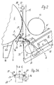
- Figure 1 can be seen a vacuum or vacuum belt conveyor 8, which is used to transport a moving web, preferably a threading-9, namely from the last drying cylinder 6 of a papermaking machine, for example, to a multi-roll calender 7th It is known, a threading-Bändel Part of a moving web, such as a paper or board web: it is needed for threading the web into the papermaking or paper finishing machine. Before the threading operation, the web runs down the path 9a ( Figures 1 and 2), being guided by the cylinder 6 into a broke bin (not shown) by a machine-wide doctor 18.
- a threading-9 namely from the last drying cylinder 6 of a papermaking machine, for example, to a multi-roll calender 7th
- a threading-Bändel Part of a moving web such as a paper or board web: it is needed for threading the web into the papermaking or paper finishing machine.
- the web runs down the path 9a ( Figures 1 and 2), being guided by the cylinder 6
- the vacuum belt conveyor 8 comprises an air-permeable, endless conveyor belt 10, which passes over two rollers 11, 12 and via a suction box or vacuum box 15.
- the two rollers 11, 12 are rotatably arranged in holders (not shown), which are attached to the suction box 15.
- One of the rollers is provided with a drive, not shown.
- a vacuum source 17 for generating negative pressure in the suction box 15th
- the suction box 15 has a cover plate 16 in which slots (or similar openings) are provided. On this plate slides the conveyor run of the air-permeable conveyor belt 10; As a result, the threading tape 9 is sucked onto the conveyor belt and transported.
- a so-called nose shoe 50 and a pivotable guide plate 63 (which are known from EP 1 076 130) are provided at the discharge end of the conveyor 8. After a successful threading procedure, the strip 9 is widened in a known manner; the complete web, designated by 9 'in FIGS.
- the suction box 15 is shaped (in a known manner) as an elongate body. Other types, e.g. have an internal means for generating a negative pressure at the conveyor run of the belt 10 may also be used.
- a total of 20 designated assembly is provided;
- This is a Bändel transfer device according to the invention.
- These include a pneumatic guide plate 22 and a low-pressure chamber 24, which is connected via a line 25 to a compressed air source 26, further a strip-separating device 21 in the form of two so-called edge nozzles.
- Each edge nozzle 21 is arranged in operation in one of the edge regions of the ribbon 9, see Figure 2A.
- Each edge nozzle 21 is suitable for ejecting a high-energy air jet onto the web-emitting lateral surface 6a of the cylinder 6. This ensures that the downwardly running strip 9 is detached from the cylinder jacket surface 6a and that at the same time the strip is severed transversely. From now on, the tape 9 runs with a new beginning of the tape on the guide plate 22 to the conveyor belt 10 and with this towards calender. 7
- the width b is of the order of magnitude 0.2 m) of the strip 9 only a fraction of the usual width of the paper web to be produced or to be finished. It is understood that the working width of the entire web conveying device is adapted to the Bändelbreite b. However, it is also conceivable to execute a transfer device according to the invention in machine-width in a relatively narrow paper-processing machine.
- the guide plate 22 In the rest position of the assembly 20, the guide plate 22 is approximately parallel to the belt conveyor 8; In this case, the distance between the cylinder jacket surface 6a and the edge nozzles 21 is greater by a multiple than in the working position. If necessary, you can also place the assembly 20 temporarily in a middle, provided between the rest and working position intermediate position. Furthermore, a (known) pivoting means, not shown, can be provided to the Entire device (belt conveyor 8 with module 20) carefully spas to the range of the machine.
- the edge nozzles 21 are, as shown, preferably fixed immovably in the assembly 20. However, it is also conceivable that the edge nozzles are movable relative to the guide plate 22.
- the assembly 20 comprises a high-pressure chamber 34 to which both edge nozzles 21 are connected (FIGS. 2 and 3).
- the high-pressure chamber 34 can be connected via a high-pressure line 36 to a high-pressure source 35.
- a control valve 37 is provided, which by means of a time signal (line 38) briefly, z. B. for 0.05 to 0.5 seconds, can be opened. It is important that the edge nozzles 21 eject the high-energy air jet only for a short time so that the new beginning of the ribbon 9 continues as far as possible without damage.
- each fringe nozzle can be assigned its own control valve (FIG. 2A).
- the edge nozzles 21 together form a C-shaped pipe section 40 or 41 (in which the high-pressure line 36 opens) z. 4 or 5.
- the peripheral nozzles can be formed as Laval nozzles (21A, FIG.
- the assembly 20 comprises the high-pressure chamber 34 formed from a rectangular hollow profile and the guide plate 22 which has at least one step at 42 and optionally at 42a and which is stepped at 43 fixed to the high-pressure chamber 34. Said elements 22 and 34 together with other walls 45, 46 delimit the already mentioned low-pressure chamber 24.
- the step 42 (and optionally at the step 42a) there is a series of blowing apertures extending across the plate and through which Air from the chamber 24 flows.
- additional blow holes 34 are provided on the high-pressure chamber, which emit simultaneously with the edge nozzles 21 short-term high-energy air jets. All of these blow holes create airflows that line the tape along the guide plate 22 in the direction of the belt conveyor 8 lead.
- the number of stages 42, 42a and 43 may be greater or less than shown in the drawing.
- the approximately parallel to the lateral surface 6a extending wall 45 may have a downwardly extending extension to guide the severed part 9a of the strip down. Again, if necessary, a step with blow holes may be provided at 48.
- the guide plate 22 has an air guide 49 at its end, located near the conveyor run of the belt 10; this is curved against the direction of the conveyor run; their effect has already been described above.
- an elastic, the band 10 slightly touching seal 60 may be provided.
- the high-pressure chamber 34a including the C-shaped pipe section 40 (which forms the edge nozzles 21), is designed such that the blowing openings 43a active at the same time as the edge nozzles are positioned at the smallest possible distance from the cylinder jacket surface 6a.
- FIG. 7 shows that a banding transfer device 20 "according to the invention, consisting of edge nozzles 21 and a pneumatic guide plate 22, also for this purpose can serve a detached from a cylinder surface 6 a strip 9 not to a belt conveyor but to another transport device, eg. B. to convict a cable guide system 70.
- a banding transfer device 20 consisting of edge nozzles 21 and a pneumatic guide plate 22, also for this purpose can serve a detached from a cylinder surface 6 a strip 9 not to a belt conveyor but to another transport device, eg. B. to convict a cable guide system 70.
- FIG. 7 shows that a banding transfer device 20 "according to the invention, consisting of edge nozzles 21 and a pneumatic guide plate 22, also for this purpose can serve a detached from a cylinder surface 6 a strip 9 not to a belt conveyor but to another transport device, eg. B. to convict a cable guide system 70.
- two ropes 71 and 72 which
- edge nozzles 21 emit a short-term high-energy air jet in order to detach a ribbon from the cylinder jacket 6a and at the same time sever it transversely, so that a new ribbon beginning is fed to the cable management system 70 without formation of a double ribbon.
- Double arrow 69 indicates that the device 20 "can be displaced back and forth between a working and a rest position, similar to that described above with reference to FIG.
Landscapes
- Paper (AREA)
- Advancing Webs (AREA)
- Preliminary Treatment Of Fibers (AREA)
- Replacement Of Web Rolls (AREA)
Claims (17)
- Dispositif pour le transfert d'une bande continue, à base d'un matériau flexible, en particulier d'une bande de papier ou d'une bandelette d'insertion (9), qui fait partie d'une bande de papier continue, d'une surface de guidage de bande (6a) délivrant la bande à un dispositif de transport de bande (22), en particulier dans une machine pour la fabrication ou le façonnage d'une bande de papier, présentant les caractéristiques suivantes :a) sur au moins l'un des bords de la bande ou de la bandelette (9), il est prévu au moins une buse marginale (21) pour le décollement de la bande ou de la bandelette (9) de la surface de guidage de bande (6a) ;b) un dispositif de séparation sert à la séparation transversale de la bande ou de la bandelette (9) et à la formation d'un nouveau début, à amener au dispositif de transport de bande (22), de la bande ou de la bandelette ;c) l'au moins une buse marginale (21) exerce en supplément la fonction du dispositif de séparation, sachant qu'elle est conçue de telle sorte qu'elle expulse brièvement un jet d'air à haute énergie entre la surface de guidage de bande (6a) délivrant la bande et la bande ou la bandelette (9),
caractérisé en ce que,d) il est prévu un ensemble (20, 20', 20") comprenant l'au moins une buse marginale (21) et une plaque de guidage (22) pneumatique pour le transport de bande sur laquelle l'au moins une buse marginale (21) est fixée ;e) l'ensemble (20, 20', 20") est mobile, de sorte qu'une distance (a) entre lui et la surface de guidage de bande (6a) délivrant la bande est variable ;f) il est prévu un transporteur à bande sous vide (8) qui prend en charge la bande ou la bandelette (9) sur la plaque de guidage (22) pneumatique et la transmet. - Dispositif selon la revendication 1, caractérisé en ce que l'ensemble (20) est soutenu sur la zone d'entrée du transporteur à bande sous vide (8).
- Dispositif selon la revendication 1 ou 2, caractérisé par les caractéristiques suivantes :a) l'ensemble (20) peut être basculé à partir d'une position de repos dans une position de travail ou dans le sens contraire ;b) dans la position de repos, la plaque de guidage (22) s'étend au moins approximativement parallèlement à un brin de transport d'une bande (10) du convoyeur à bande sous vide (8) ;c) dans la position de travail, la plaque de guidage (22) est inclinée vers le brin de transport de la bande (10) ;d) la distance entre la surface de guidage de bande (6a) délivrant la bande et l'ensemble (20) est plusieurs fois supérieure dans la position de repos par rapport à la position de travail.
- Dispositif selon la revendication 3, caractérisé en ce que l'ensemble (20) peut être bloqué temporairement dans une position intermédiaire centrale, prévue entre la position de repos et la position de travail.
- Dispositif selon l'une quelconque des revendications 1 à 4, caractérisé par les caractéristiques suivantes :a) sur chacun des deux bords de la bandelette (9) il est prévu à chaque fois au moins une buse marginale (21) ;b) les buses marginales (21) présentes sur les deux bords sont en liaison l'une avec l'autre au moyen d'une conduite d'arrivée commune d'air comprimé (40, 41) ;c) la conduite d'arrivée d'air comprimé (40, 41) s'étend transversalement à la plaque de guidage (22) et est soutenue sur celle-ci.
- Dispositif selon l'une quelconque des revendications 1 à 5, caractérisé en ce que la plaque de guidage (22) présente des ouvertures de soufflage (43, 43a) supplémentaires directement sur leur extrémité côté arrivée, pour générer un écoulement d'air favorisant le transport de la bande ou de la bandelette (9).
- Dispositif selon la revendication 6, caractérisé en ce que les ouvertures de soufflage (43, 43a) supplémentaires sont conçues de telle sorte qu'elles expulsent au moins approximativement en même temps que les buses de soufflage marginales (21) des jets d'air à haute énergie de courte durée.
- Dispositif selon la revendication 6 ou 7, caractérisé en ce que la conduite d'arrivée d'air comprimé (40, 41) attribuée aux buses marginales (21) présente les ouvertures de soufflage (43, 43a) supplémentaires citées.
- Dispositif selon l'une quelconque des revendications 1 à 8, caractérisé en ce que chaque buse marginale (21) présente une vanne de commande (23) qui lui est propre.
- Dispositif selon l'une quelconque des revendications précédentes, caractérisé en ce que la plaque de guidage (22) présente sur son extrémité côté entrée une arête (50) arrondie qui fait dévier, avec l'utilisation de l'effet de Coanda, un écoulement d'air dans la direction allant au-delà de la plaque de guidage (22).
- Dispositif selon l'une quelconque des revendications précédentes, caractérisé en ce qu'il est prévu au moins une buse marginale (21 A) conçue comme buse de Laval.
- Dispositif selon l'une quelconque des revendications précédentes, caractérisé en ce qu'à au moins l'un des deux bords de la bandelette (9) sont attribuées deux buses de soufflage marginales (21) qui conviennent pour expulser en même temps ou de façon directement consécutive des jets d'air de courte durée.
- Dispositif selon l'une quelconque des revendications précédentes, caractérisé en ce que la plaque de guidage (22) présente à la façon d'une cascade plusieurs rangées disposées les unes derrière les autres d'ouvertures de soufflage (42, 42a) et/ou "buses Coanda".
- Dispositif selon l'une quelconque des revendications précédentes, caractérisé en ce que la plaque de guidage (22) présente sur son extrémité côté écoulement, située à proximité du brin de transport de la bande (10), une goulotte de guidage d'air (49) incurvée et s'éloignant du trajet de passage de la bande ou de la bandelette.
- Dispositif selon l'une quelconque des revendications précédentes, caractérisé par un dispositif de commande (37 et/ou 23), qui limite dans le temps à 0,05 à 0,5 s l'expulsion du jet d'air à haute énergie à la sortie de la/des buse(s) marginale(s) (21) et éventuellement des ouvertures de soufflage (43) supplémentaires.
- Dispositif selon l'une quelconque des revendications précédentes, caractérisé en ce que la (les) buse (s) marginale (s) (21) et éventuellement les ouvertures de soufflage (43) supplémentaires sont raccordées à une source de haute pression (35), qui génère une pression d'air d'au moins 5 bars, de préférence 7 à 10 bars.
- Dispositif selon l'une quelconque des revendications précédentes, caractérisé en ce que la surface de guidage de bande (6a) délivrant la bande est le dernier tambour sécheur à l'intérieur d'une machine de fabrication ou de façonnage.
Applications Claiming Priority (2)
| Application Number | Priority Date | Filing Date | Title |
|---|---|---|---|
| DE10115618 | 2001-03-26 | ||
| DE2001115618 DE10115618A1 (de) | 2001-03-26 | 2001-03-26 | Verfahren und Vorrichtung zum Überführen einer Bahn |
Publications (2)
| Publication Number | Publication Date |
|---|---|
| EP1245729A1 EP1245729A1 (fr) | 2002-10-02 |
| EP1245729B1 true EP1245729B1 (fr) | 2006-10-11 |
Family
ID=7679586
Family Applications (1)
| Application Number | Title | Priority Date | Filing Date |
|---|---|---|---|
| EP20020005684 Expired - Lifetime EP1245729B1 (fr) | 2001-03-26 | 2002-03-13 | Dispositif de transfert d'une bande de papier |
Country Status (6)
| Country | Link |
|---|---|
| US (2) | US6928912B2 (fr) |
| EP (1) | EP1245729B1 (fr) |
| JP (1) | JP2002356272A (fr) |
| AT (1) | ATE342404T1 (fr) |
| CA (1) | CA2378831A1 (fr) |
| DE (2) | DE10115618A1 (fr) |
Cited By (1)
| Publication number | Priority date | Publication date | Assignee | Title |
|---|---|---|---|---|
| EP1972718A2 (fr) | 2007-03-23 | 2008-09-24 | Voith Patent GmbH | Dispositif de guidage ou de transfert d'une bande en papier, carton ou autre matière fibreuse |
Families Citing this family (24)
| Publication number | Priority date | Publication date | Assignee | Title |
|---|---|---|---|---|
| FI112876B (fi) | 2002-10-16 | 2004-01-30 | Metso Paper Inc | Järjestely päänviennissä paperikoneen monitelakalanterilla |
| CA2413104A1 (fr) * | 2002-11-28 | 2004-05-28 | Voith Paper Patent Gmbh | Methode et appareil de transfert de bobines de papier |
| US7117775B2 (en) * | 2002-12-12 | 2006-10-10 | Voith Paper Patent Gmbh | Method and apparatus for transferring a paper web |
| US6846151B2 (en) * | 2003-02-21 | 2005-01-25 | Lockhead Martin Corporation | Non-contact aerodynamic diverter/stacker insertion system |
| RU2007114909A (ru) * | 2004-09-20 | 2008-11-10 | БАЙЕР ХЕЛТКЭА ЭлЭлСи (US) | Устройство с зазубренным ножом для распределения датчиков уровня глюкозы в крови |
| US7849770B2 (en) * | 2004-10-07 | 2010-12-14 | Douglas Machine, Inc. | Film cutter |
| US20060075861A1 (en) * | 2004-10-07 | 2006-04-13 | Flooding Daniel L | Film cutter |
| FI119441B (fi) * | 2007-08-20 | 2008-11-14 | Runtech Systems Oy | Menetelmä paperirainan muodonmuutoksien kompensoimiseksi |
| DE102008000133A1 (de) * | 2008-01-23 | 2009-07-30 | Voith Patent Gmbh | Trockenpartie |
| DE102008002260A1 (de) | 2008-06-06 | 2009-12-10 | Voith Patent Gmbh | Vorrichtung zum Führen bzw. Überführen einer Faserstoffbahn |
| DE102008002346A1 (de) | 2008-06-11 | 2009-12-17 | Voith Patent Gmbh | Vorrichtung zum Überführen einer Faserstoffbahn |
| DE102008044226A1 (de) | 2008-12-01 | 2010-06-02 | Voith Patent Gmbh | Vorrichtung zum Führen bzw. Überführen einer Faserstoffbahn |
| US8177940B2 (en) * | 2009-03-04 | 2012-05-15 | Andritz Inc. | Apparatus and method for stabilizing a moving web having transitions in a surface adjacent the web |
| FI20090288A0 (fi) * | 2009-07-30 | 2009-07-30 | Runtech Systems Oy | Menetelmä päänvientinauhan siirtämiseksi rakenneryhmältä toiselle sekä laitteisto ja sen käyttö |
| US9138781B1 (en) * | 2011-02-25 | 2015-09-22 | John Bean Technologies Corporation | Apparatus and method for harvesting portions with fluid nozzle arrays |
| DE102011016588A1 (de) * | 2011-04-08 | 2012-10-11 | Andritz Küsters Gmbh | Vorrichtung zum Überführen einer Bahn in einer Station einer Bahn-Herstellungs- oder Verarbeitungsmaschine |
| DE102015001008A1 (de) | 2015-01-28 | 2016-07-28 | Andritz Küsters Gmbh | Verfahren und Vorrichtung zur Herstellung von nassgelegten Vliesstoffen |
| DE102015005384A1 (de) | 2015-04-28 | 2016-11-03 | Andritz Küsters Gmbh | Verfahren und Vorrichtung zur Herstellung von nassgelegten Vliesstoffen |
| CN109250441A (zh) * | 2018-11-19 | 2019-01-22 | 佛山市宝索机械制造有限公司 | 卷材尾端定向输送装置 |
| CN111596089B (zh) * | 2020-04-22 | 2022-04-12 | 安徽楚江高精铜带有限公司 | 一种led铜带高精度速度测量装置 |
| DE102020128265A1 (de) * | 2020-10-28 | 2022-04-28 | Voith Patent Gmbh | Alternatives Saugwalzenkonzept |
| CN113201959B (zh) * | 2021-05-25 | 2022-11-15 | 于都县正亿纸品纸业有限公司 | 造纸设备中的纸边控制装置及其使用方法 |
| DE102024117961A1 (de) * | 2024-06-26 | 2025-12-31 | Voith Patent Gmbh | Vorrichtung und Verfahren zum Überführen einer Faserstoffbahn |
| DE102024117960A1 (de) * | 2024-06-26 | 2025-12-31 | Voith Patent Gmbh | Vorrichtung und Verfahren zum Überführen einer Faserstoffbahn |
Family Cites Families (16)
| Publication number | Priority date | Publication date | Assignee | Title |
|---|---|---|---|---|
| US1279756A (en) * | 1918-03-14 | 1918-09-24 | Great Northern Paper Co | Method and machine for making paper. |
| US1595478A (en) * | 1920-05-25 | 1926-08-10 | Minton Ogden | Method of stripping and feeding paper and apparatus |
| US1688267A (en) | 1927-08-19 | 1928-10-16 | Great Northern Paper Co | Paper making |
| US1878184A (en) * | 1927-11-15 | 1932-09-20 | Wood Newspaper Mach Corp | Pneumatic web severing device |
| US3355349A (en) * | 1964-12-14 | 1967-11-28 | Andrew G Devlin | Apparatus for conveying lead strip from driers to calenders in paper-making |
| US3999696A (en) * | 1975-05-27 | 1976-12-28 | Crown Zellerbach Corporation | Web threading system |
| FI62695C (fi) * | 1981-05-15 | 1983-02-10 | Valmet Oy | Anordning i en pappersmaskin foer kapning och styrning av en pappersbanans kantremsa |
| FI78528C (fi) * | 1988-01-26 | 1989-08-10 | Valmet Paper Machinery Inc | Foerfarande och anordning foer styrning av pappersbanans spetsdragningsband fraon pressens slaetytade vals eller motsvarande. |
| FI80921C (fi) * | 1988-08-25 | 1990-08-10 | Ahlstroem Valmet | Foerfarande och anordning i samband med spetsdragningen av en pappersbana. |
| CA2028443C (fr) * | 1990-10-24 | 1996-04-30 | Stanley Hui Mah | Dispositif de mise en route de l'amorce du papier par rotation inversee des couteaux |
| US5377930A (en) * | 1993-01-15 | 1995-01-03 | International Paper Company | Paper turn-up system and method |
| SE504708C2 (sv) * | 1995-09-13 | 1997-04-07 | Valmet Karlstad Ab | Sätt och anordning för överföring av en snabbt löpande färdigtorkad fiberbana, särskilt en tissuebana, från en anordning och längs en förutbestämd bana till en efterföljande anordning |
| DE19929927A1 (de) * | 1999-06-29 | 2001-01-04 | Voith Paper Patent Gmbh | Vorrichtung zum Trennen und Überführen eines Einführstreifens |
| US6270629B1 (en) * | 1999-08-13 | 2001-08-07 | Voith Sulzer Papertechnik Patent Gmbh | Web handling apparatus |
| DE19962731A1 (de) * | 1999-12-23 | 2001-06-28 | Voith Paper Patent Gmbh | Bahnfördereinrichtung |
| DE10146538A1 (de) * | 2001-09-21 | 2003-04-10 | Voith Paper Patent Gmbh | Verfahren und Vorrichtung zum Überführen einer Papierbahn |
-
2001
- 2001-03-26 DE DE2001115618 patent/DE10115618A1/de not_active Withdrawn
-
2002
- 2002-03-13 DE DE50208374T patent/DE50208374D1/de not_active Expired - Fee Related
- 2002-03-13 AT AT02005684T patent/ATE342404T1/de not_active IP Right Cessation
- 2002-03-13 EP EP20020005684 patent/EP1245729B1/fr not_active Expired - Lifetime
- 2002-03-20 US US10/102,160 patent/US6928912B2/en not_active Expired - Fee Related
- 2002-03-25 JP JP2002083750A patent/JP2002356272A/ja active Pending
- 2002-03-25 CA CA 2378831 patent/CA2378831A1/fr not_active Abandoned
-
2005
- 2005-02-16 US US11/059,006 patent/US20050167065A1/en not_active Abandoned
Cited By (1)
| Publication number | Priority date | Publication date | Assignee | Title |
|---|---|---|---|---|
| EP1972718A2 (fr) | 2007-03-23 | 2008-09-24 | Voith Patent GmbH | Dispositif de guidage ou de transfert d'une bande en papier, carton ou autre matière fibreuse |
Also Published As
| Publication number | Publication date |
|---|---|
| EP1245729A1 (fr) | 2002-10-02 |
| ATE342404T1 (de) | 2006-11-15 |
| US6928912B2 (en) | 2005-08-16 |
| US20020148874A1 (en) | 2002-10-17 |
| JP2002356272A (ja) | 2002-12-10 |
| CA2378831A1 (fr) | 2002-09-26 |
| DE10115618A1 (de) | 2002-10-02 |
| DE50208374D1 (de) | 2006-11-23 |
| US20050167065A1 (en) | 2005-08-04 |
Similar Documents
| Publication | Publication Date | Title |
|---|---|---|
| EP1245729A1 (fr) | Procédé et dispositif de transfert d'une bande de papier | |
| DE69613231T2 (de) | Verfahren und vorrichtung zur übergabe einer schnellaufenden trockenen faserbahn, insbesondere einer tissuebahn, von einer vorrichtung und entlang einer bestimmten bahn zu einer nachfolgenden vorrichtung | |
| EP0995707B1 (fr) | Enrouleuse | |
| EP0639668A2 (fr) | Section de séchage | |
| DE3524006A1 (de) | Vorrichtung in einer papiermaschine zum transport und zur fuehrung des bahnendauffuehrungsbandes | |
| EP1205415A2 (fr) | Transporteur à courroie aspirante | |
| DE3344217A1 (de) | Vorrichtung zum ueberfuehren einer papierbahn von der pressen- in die trockenpartie einer papiermaschine | |
| DE29924658U1 (de) | Vorrichtung zum Befördern und Führen eines Einführstreifens einer Bahn bei einer Papiermaschine | |
| EP2217759B1 (fr) | Dispositif pour transférer une bande de papier d'une bande de soutien a une autre | |
| EP1283185A2 (fr) | Méthode pour enrouler une bande de matériau en mouvement et enrouleuse pour la mise en oeuvre du procédé | |
| EP0674044B1 (fr) | Procédé et dispositif de guidage d'une bande de matériau | |
| DE19962731A1 (de) | Bahnfördereinrichtung | |
| DE60133328T2 (de) | Verfahren und Vorrichtung zum Bahneinzug in die Trockenpartie einer Papiermaschine oder dergleichen | |
| EP1038817B1 (fr) | Méthode et dispositif pour guider une bande de matériau sur un tambour | |
| EP1440926B1 (fr) | Transporteur a courroie aspirante et machine comportant un tel convoyeur pour la fabrication ou la finition d'une bande de papier | |
| EP1065313B1 (fr) | Dispositif pour séparer et enfiler la bande directrice | |
| DE19848806A1 (de) | Verfahren zum Aufführen einer Materialbahn auf einen Tambour und Vorrichtung zur Durchführung des Verfahrens | |
| EP1354677A2 (fr) | Dispositif de coupe à jet d'eau | |
| EP1972718A2 (fr) | Dispositif de guidage ou de transfert d'une bande en papier, carton ou autre matière fibreuse | |
| AT410684B (de) | Einfädelvorrichtung und verfahren zum einfädeln des endes einer bahn | |
| DE4328554A1 (de) | Trockenpartie | |
| DE10358155B4 (de) | Vorrichtung zum Überführen einer Materialbahn | |
| DE3731541C2 (de) | Verfahren und Vorrichtung zur stabilisierten Führung einer bewegten Materialbahn | |
| EP1200329B1 (fr) | Procede et dispositif pour raccourcir le drapeau forme suite au remplacement de bobines | |
| AT11148U1 (de) | Vorrichtung zum führen bzw. überführen einer faserstoffbahn |
Legal Events
| Date | Code | Title | Description |
|---|---|---|---|
| PUAI | Public reference made under article 153(3) epc to a published international application that has entered the european phase |
Free format text: ORIGINAL CODE: 0009012 |
|
| AK | Designated contracting states |
Kind code of ref document: A1 Designated state(s): AT BE CH CY DE DK ES FI FR GB GR IE IT LI LU MC NL PT SE TR |
|
| AX | Request for extension of the european patent |
Free format text: AL;LT;LV;MK;RO;SI |
|
| 17P | Request for examination filed |
Effective date: 20030402 |
|
| AKX | Designation fees paid |
Designated state(s): AT DE FI SE |
|
| 17Q | First examination report despatched |
Effective date: 20040220 |
|
| GRAP | Despatch of communication of intention to grant a patent |
Free format text: ORIGINAL CODE: EPIDOSNIGR1 |
|
| RTI1 | Title (correction) |
Free format text: DEVICE FOR TRANSFERRING A WEB |
|
| GRAS | Grant fee paid |
Free format text: ORIGINAL CODE: EPIDOSNIGR3 |
|
| GRAA | (expected) grant |
Free format text: ORIGINAL CODE: 0009210 |
|
| RAP1 | Party data changed (applicant data changed or rights of an application transferred) |
Owner name: VOITH PATENT GMBH |
|
| AK | Designated contracting states |
Kind code of ref document: B1 Designated state(s): AT DE FI SE |
|
| PG25 | Lapsed in a contracting state [announced via postgrant information from national office to epo] |
Ref country code: FI Free format text: LAPSE BECAUSE OF FAILURE TO SUBMIT A TRANSLATION OF THE DESCRIPTION OR TO PAY THE FEE WITHIN THE PRESCRIBED TIME-LIMIT Effective date: 20061011 |
|
| REF | Corresponds to: |
Ref document number: 50208374 Country of ref document: DE Date of ref document: 20061123 Kind code of ref document: P |
|
| PG25 | Lapsed in a contracting state [announced via postgrant information from national office to epo] |
Ref country code: SE Free format text: LAPSE BECAUSE OF FAILURE TO SUBMIT A TRANSLATION OF THE DESCRIPTION OR TO PAY THE FEE WITHIN THE PRESCRIBED TIME-LIMIT Effective date: 20070111 |
|
| PLBE | No opposition filed within time limit |
Free format text: ORIGINAL CODE: 0009261 |
|
| STAA | Information on the status of an ep patent application or granted ep patent |
Free format text: STATUS: NO OPPOSITION FILED WITHIN TIME LIMIT |
|
| 26N | No opposition filed |
Effective date: 20070712 |
|
| PG25 | Lapsed in a contracting state [announced via postgrant information from national office to epo] |
Ref country code: DE Free format text: LAPSE BECAUSE OF NON-PAYMENT OF DUE FEES Effective date: 20071002 |
|
| PG25 | Lapsed in a contracting state [announced via postgrant information from national office to epo] |
Ref country code: AT Free format text: LAPSE BECAUSE OF NON-PAYMENT OF DUE FEES Effective date: 20070313 |