EP0639668A2 - Section de séchage - Google Patents
Section de séchage Download PDFInfo
- Publication number
- EP0639668A2 EP0639668A2 EP94111918A EP94111918A EP0639668A2 EP 0639668 A2 EP0639668 A2 EP 0639668A2 EP 94111918 A EP94111918 A EP 94111918A EP 94111918 A EP94111918 A EP 94111918A EP 0639668 A2 EP0639668 A2 EP 0639668A2
- Authority
- EP
- European Patent Office
- Prior art keywords
- felt
- dryer
- group
- cylinders
- web
- Prior art date
- Legal status (The legal status is an assumption and is not a legal conclusion. Google has not performed a legal analysis and makes no representation as to the accuracy of the status listed.)
- Granted
Links
Images


Classifications
-
- D—TEXTILES; PAPER
- D21—PAPER-MAKING; PRODUCTION OF CELLULOSE
- D21G—CALENDERS; ACCESSORIES FOR PAPER-MAKING MACHINES
- D21G9/00—Other accessories for paper-making machines
- D21G9/0063—Devices for threading a web tail through a paper-making machine
- D21G9/0072—Devices for threading a web tail through a paper-making machine using at least one rope
-
- D—TEXTILES; PAPER
- D21—PAPER-MAKING; PRODUCTION OF CELLULOSE
- D21F—PAPER-MAKING MACHINES; METHODS OF PRODUCING PAPER THEREON
- D21F5/00—Dryer section of machines for making continuous webs of paper
- D21F5/02—Drying on cylinders
- D21F5/04—Drying on cylinders on two or more drying cylinders
-
- D—TEXTILES; PAPER
- D21—PAPER-MAKING; PRODUCTION OF CELLULOSE
- D21F—PAPER-MAKING MACHINES; METHODS OF PRODUCING PAPER THEREON
- D21F5/00—Dryer section of machines for making continuous webs of paper
- D21F5/02—Drying on cylinders
- D21F5/04—Drying on cylinders on two or more drying cylinders
- D21F5/042—Drying on cylinders on two or more drying cylinders in combination with suction or blowing devices
-
- D—TEXTILES; PAPER
- D21—PAPER-MAKING; PRODUCTION OF CELLULOSE
- D21G—CALENDERS; ACCESSORIES FOR PAPER-MAKING MACHINES
- D21G9/00—Other accessories for paper-making machines
- D21G9/0063—Devices for threading a web tail through a paper-making machine
Definitions
- the invention relates to a dryer section for drying a running web, preferably as part of a paper making machine.
- the starting point of the invention is a dryer section with the features specified in the preamble of claim 1, which are known from DE-PS 4037661 (file P 4748).
- Such a dryer section is divided into several successive dryer groups.
- Each of these drying groups comprises a plurality of heatable drying cylinders which come into contact with the web and which are coupled to a (preferably common) drive.
- single-felt dryer groups each of which has only a single endless felt (or such a sieve). This felt runs together with the web in a meandering shape over the cylinders and over deflection rollers, preferably deflection suction rollers.
- Such one-felt dryer groups are usually provided in the initial area of the dryer section, to which the web to be dried is fed in a still relatively moist state (with a dry content of approximately 35-55%, depending on the paper type and working speed).
- one or more two-felt dryer groups are provided in the end region of the dryer section.
- Each of these dryer groups has an upper and a lower row of cylinders, the web running alternately over the upper and lower cylinders.
- the two-felt dryer group (s) can directly follow the last one-felt dryer group, or an additional unit (size press, dampening unit or the like) is inserted in between.
- Such a dryer section which comprises at least one single-felt and at least one subsequent two-felt dryer group, is hereinafter referred to as "mixed dryer section".
- One aspect of the invention addresses the problem of how the total web contact area of the mixed dryer section each according to the type of paper to be divided between the cylinders of the one-felt dryer group (s) and the cylinders of the two-felt dryer group (s). If the proportion of two-felt dryer groups is relatively large, so that the web dry content when entering the first two-felt dryer group is still relatively low, there is an increased risk of paper web tears, because the web is still in relatively moist condition free, ie runs from cylinder to cylinder unsupported. Threading the web when starting the machine can also be difficult.
- the entire dryer section or almost the entire dryer section is composed of single-felt dryer groups, other disadvantages must be accepted:
- the dryer section requires more space in the longitudinal direction and thus causes higher building costs.
- a one-felt dryer group located at the end of the dryer section considerable longitudinal tensions can build up in the paper web because the paper web has little or no possibility of shrinking in the longitudinal direction; there is again the risk of paper web tears.
- placing a tip cutter at the end of the dryer section is difficult. Sometimes there is also increased felt wear.
- Another aspect of the present invention addresses the problem of threading the web to be dried into the dryer section.
- the mechanically dewatered web formed in the initial part of the paper making machine temporarily runs during the start-up phase at full working speed only to the end of the press section or to the first drying cylinder of the drying section. From there it goes down to a reject breakdown facility. A narrow edge strip is now separated from the web, hereinafter referred to as "ribbon".
- an automatic rope-less ribbon guide device is also provided in the two-felt dryer group (s) according to the invention.
- Suitable elements of various types are known per se from the following publications: DE-PS 1 245 278, DE-GM 8 914 679 (file P 4692), DE-GM 9 109 313 (file P 4829).
- the measures according to the invention ensure that the paper web, in particular the ribbon, at the boundary between the one-felt and the two-felt dryer groups achieves a sufficiently high degree of rigidity and tensile strength to ensure that the threading process done automatically with great reliability.
- the paper web at the discharge point of each drying cylinder adheres relatively strongly to its surface.
- Another aspect of the invention relates to advantageous arrangements of the cylinders and felt guide rollers in the transition area between the last one-felt dryer group and the subsequent two-felt dryer group. (Claims 7 to 9). It is particularly favorable if the web can pass through the separation point between the two drying groups mentioned essentially from top to bottom.
- a still further aspect of the invention is concerned with the problem of reject paper removal which occasionally arises in the event of a paper web tear. This danger, which can never be completely ruled out, is particularly evident in the initial area of the dryer section, i.e. in the area of the single-felt dryer groups. It is most advantageous if, according to claim 10 or 12, all single-felt dryer groups are felted at the top; then the paper board can easily escape under the force of gravity. The most common arrangement of the cylinders in horizontal rows does not cause any problems.
- the latter protects, among other things, a dryer section configuration with several V-shaped and top-felted dryer groups and with two bottom-felted and V-shaped dryer groups, whereby a gap can be opened between the bottom cylinders of these two dryer groups for the purpose of removing scrap paper .
- deflection rollers already mentioned above and required in the single-felt drying groups are designed as suction rollers, then these can be provided in a conventional manner with an inner stationary suction box, which can also serve to limit a desired suction zone.
- an inner stationary suction box which can also serve to limit a desired suction zone.
- a construction is preferred according to claim 14, in which the The interior of the deflection suction rolls is free of stationary internals. It is also not necessary to produce a hollow pin which is used to extract air, in order to generate negative pressure inside the roll. Rather, an external suction box is provided (for example in the pocket between two adjacent drying cylinders), preferably in accordance with patent application EP 94109372.6 (file PA 10082).
- Another aspect of the invention addresses the problem of how high above a horizontal reference plane, e.g. B. above the paper machine floor, the axes of rotation of the cylinders and / or deflection rollers of the single-felt dryer group (s) are advantageously arranged, e.g. with regard to the necessary free evaporation path of the paper web between two cylinders.
- Another aspect is the arrangement of these axes of rotation relative to the planes in which the axes of rotation of the cylinders of the subsequent two-felt dryer group lie.
- particularly advantageous solutions are given in claims 15 to 17.
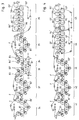
- 1 to 4 show schematic side views of several different dryer sections with several one-felt dryer groups and with at least one subsequent two-felt dryer group.
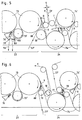
- FIGS. 1 to 4 show (compared to FIGS. 1 to 4 enlarged) schematic side views of the transition zone between a one-felt drying group and a subsequent two-felt drying group with the associated ribbon guide devices.
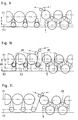
- FIGS. 9 to 11 are similar to FIGS. 5 to 8 and show different height distances of the cylinder or deflecting roller axes from a reference plane.
- 18A-18D show different transition points between a felted single-felt dryer group below and a subsequent two-felt dryer group.
- 19 and 20 are schematic side views of further dryer sections according to the invention.
- the dryer section shown in FIG. 1 initially has six single-felt dryer groups 11-16 arranged one behind the other. Each of these dryer groups has a single endless felt F.
- the felt F runs together with the web 9 alternately over drying cylinders 51 and over deflection rollers 51 ', which are preferably designed as suction rollers.
- the underside of the web comes into contact with the cylinders in the first two dryer groups 11 and 12 and in the fourth and sixth dryer groups 14, 16. Accordingly, the drying cylinders 51, 52, 54, 56 are located above the associated deflection suction rolls 51 ', 52', 54 'and 56'; the cylinders are "felted on top".
- the paper web 9 forms a short open train at each of these turning separation points; ie it is temporarily not supported by a felt. It runs in the area of a small suction zone of a transfer roller 58 onto the next felt in each case.
- Transfer rollers 58 are the only suction rollers with an internal stationary suction box.
- the deflection suction rolls 51 'to 56' are free of internal stationary installations and of direct suction connections. Instead, an external suction box 59 is provided on each of these deflection suction rolls. This lies in the so-called pocket between two adjacent drying cylinders and has a strip 60 at the point where felt F and web 9 together leave the first of these two cylinders (see FIG. 7), which strips and deflects the air boundary layer transported by the felt .
- the last one-felt dryer group 16 is followed by a two-felt dryer group 17 with some lower cylinders 57 and some upper cylinders 57 ', as well as with a bottom felt UF with an upper felt OF.
- the web 9 runs in a meandering pattern alternately over the lower and upper cylinders.
- a tip cutter S is indicated between the last two cylinders.
- the dryer section shown in FIG. 2 has, for example, three (or four or five) single-felt dryer groups 21-23; however, in contrast to FIG. 1, these are all felted above. In other words: All drying cylinders 71-73 touch the underside of the web. Another difference from FIG. 1 is that the deflection suction rolls 71 'to 73' have internal stationary suction boxes and are arranged at a short distance from the adjacent drying cylinders. Furthermore, two (or three) two-felt dryer groups 24, 25 with lower cylinders 74, 75 and with upper cylinders 74 'and 75' are now provided, for example.
- the cylinders of the single-felt drying groups are, as such, from known from DE 4 041 493, arranged in a plurality of rows inclined against the vertical direction, rows back and forth inclined alternating in succession. 3, two V-shaped double rows form a first dryer group 31 and a second dryer group 32.
- the cylinders 81, 82 of these two dryer groups are felted at the top. This is followed by two dryer groups 33, 34 felted at the bottom.
- the three (or four) cylinders 83 of the third dryer group for example, form a backward inclined row.
- the cylinders 84 of the fourth dryer group form a forward inclined row.
- a gap can be opened between the bottom cylinders of these two drying groups 33, 34 by means of a pivotable felt guide roller 87 for the purpose of removing waste paper downwards.
- the fifth drying group 35 in turn has exclusively felted drying cylinders 85, which in turn form a V-shaped double row. Behind the last cylinder of this dryer group 35, the web is guided obliquely downwards to the first lower cylinder 86 of the subsequent two-felt dryer group 36. According to FIG. 4, only felted and V-shaped one-felt dryer groups 41, 42 and 43 are provided above, followed by two two-felt dryer groups 44 and 45. In both FIGS.
- the last two drying cylinders 73 of the last one-felt drying group 23 and the first three cylinders 74, 74 'of the two-felt drying group 24 can be seen from the drying section according to FIG. 2. Furthermore, one can be seen with an inner suction box provided deflection suction roll 73 'and (in contrast to FIG. 2) a transfer suction roll 58 in front of the first lower drying cylinder 74, likewise with a stationary inner suction box.
- An automatic rope-less ribbon guiding device is formed in the one-felt dryer group 23, for example, in that each deflection suction roll 73 has an edge suction zone known per se at one of its two ends.
- Air blowing devices which are symbolically represented by arrows, are also provided on a scraper support body 76, as well as an air blowing nozzle 79.
- a scraper support body 76 At the point where the web 9 and the felt F run together from the last cylinder 73, a (only in the area of the belt more effective) edge suction box R, web stabilizer or the like.
- a short "ribbon guide scraper" 88 which only covers the ribbon area and which can also have an air blowing nozzle (e.g. DE-GM 8 914 679).
- the arrangement shown ensures that the incoming ribbon is securely grasped and forwarded by the first cylinder 74 '; it can also be used at the point of separation between two two-felt dryer groups (e.g. 24, 25, Fig. 2), both on the top felts and on the bottom felts.
- devices which generate negative pressure can also be used for threading the band.
- the devices according to US Pat. No. 4,022,366 come into consideration. After successfully threading the ribbon, such a device can be swung out into the area outside the dryer section.
- at least one of the felt guide rollers is designed as a suction roller and is arranged in such a way that it can remove the web from another felt, similar to the method disclosed in US Pat. No. 4,485,567.
- the vacuum is temporarily switched off; in addition, the air blowing nozzle 79 is switched off, so that the ribbon initially runs down into the basement, as shown at 9A.
- a new ribbon tip 9B is formed by means of the blowing nozzle 79 and a knife 80 and is guided to the deflection suction roller 73 'which is again pressurized with vacuum.
- the ribbon now runs over to and through the two-felt dryer group 25 until the end of the dryer section.
- Such a device is also present in FIG. 7.
- a guide roller 18 of the felt F and a guide roller 19 of the bottom felt UF are arranged such that that the felts overlap each other.
- the guide roller 18 can be brought into the position shown with dash-dotted lines, so that the felts F and UF temporarily touch or almost touch each other.
- a ribbon guide scraper 88 can also be provided.
- the first cylinder 94 'of the two-felt dryer group is an upper cylinder. Therefore, a deflection suction roller 96 is provided between this and the last cylinder 93 of the one-felt dryer group. According to FIG. 7, this can lie in the loop of the felt F of the single-felt drying group, the felt F touching the upper cylinder 94 'and delivering the web 9 to it. According to FIG. 8, the deflection suction roller 96 'can lie in the upper felt OF of the two-felt drying group. This felt touches the last cylinder 93 of the one-felt dryer group and removes the web from it.
- FIG. 9 compared to FIG. 1, an increased distance H is provided between the planes E1 and E2, as a result of which the web 9 has an enlarged evaporation path between two cylinders of the single-felt drying group.
- the cylinder axes are located in E1, the axes of the deflection suction rolls in E2, and at least approximately the axes of the lower cylinders of the two-felt dryer group.
- the following is provided - in deviation from FIGS. 1 and 2:
- the axes of the cylinders of the one-felt drying group lie in the same horizontal plane E1 as the axes of the upper cylinders of the two-felt drying group.
- Uniform stands 89 can thus be provided for all these cylinders.
- this means that the axes of the cylinders of the single-felt dryer group are at a greater height distance HO above a reference plane E0 than, for example, the axes of the cylinders 56 in FIG. 1. It follows that the height distance H between the deflection suction rolls and the cylinders is also very great can choose large if - compared to Fig.
- the axes of the deflection suction rolls can in turn lie at least approximately in the same horizontal plane E2 as the axes of the lower cylinders of the two-felt dryer group.
- the advantages described can be applied even more if, according to FIG. 11, the axes of the cylinders of the one-felt drying group (level E1) are arranged above the axes of the upper cylinders of the two-felt drying groups (level E3).
- FIG. 12 shows an alternative to FIG. 1.
- the two-felt dryer group 17A is designed as follows according to DE-PS 3 623 971 (file P 4243): the paper web 9 runs first over a lower cylinder 61, then successively over two upper cylinder 62, then successively over two lower Cylinder 63, then successively via two upper cylinders 64, then successively via two lower cylinders 65 and finally via an upper cylinder 66.
- a deflection suction roller 62'-65 ' is arranged between the cylinders of each pair of cylinders 62-65.
- the ribbon pulling can take place automatically, that is to say without ropes, just as explained above with reference to FIGS. Any scrap paper that occurs is automatically transported to the rear end of the drying group 17A and ejected there.
- Fig. 13 shows that a one-felt dryer group 15A felted below can also be arranged immediately in front of a two-felt dryer group 16A.
- each lower cylinder 67, 68 has its own felt FA, FB to facilitate the removal of waste.
- an additional unit e.g., between the last one-felt drying group and the first two-felt drying group, can be used.
- a size press, a dampening unit or the like can be arranged.
- the axes of rotation of the cylinders 200 of the one-felt drying group felted below lie in a horizontal plane II and the axes of rotation of the associated deflection suction rolls lie in a plane III.
- the two planes II and III are arranged between planes IV and V, in which the axes of rotation of the upper and lower cylinders of the subsequent two-felt dryer group are arranged.
- the paper web 208 runs from the last cylinder 200 of the one-felt drying group to the first upper cylinder 202 of the two-felt drying group an approximately vertical path from bottom to top.
- the felt guide rollers 204 and 206 located here are close together, so that there is only a short free path of web travel.
- the diameter of the cylinders of the two-felt drying group are slightly smaller than the diameter of the cylinders of the one-felt drying group. This has several advantages: From paper machine floor I you can easily see the pockets that are located between the upper and lower cylinders of the two-felt dryer group. If desired, the height distance between planes IV and V can also be chosen to be relatively small in order to reduce the length of the free web trains between the cylinders. This also results in a relatively small height distance of plane IV from paper machine base I, so that upper cylinders 202 are easily accessible and operable.
- the lower felt 220 of the two-felt drying group comes into roughly tangential contact with the last cylinder 200 of the single-felt drying group, which is in turn felted below. This is a so-called lick-up flyover.
- the felt 220 takes over the paper web from the cylinder 200 and guides it via a suction guide roller 210 to the first cylinder 212 of the two-felt drying group located below.
- an air jet is directed against the jacket of the cylinder 200 by means of an air nozzle 216 (or a similar device). This ensures that the tip of the ribbon continues to run with the lower felt 220.
- the air nozzle 216 can be attached to an arm which can be pivoted outwards by means of a pivoting device 218, so that the removal of the scrap from the top of the cylinder 200 is not hindered in the event of paper scrap.
- FIG. 18C differs only slightly from FIG. 18A.
- the paper web again runs together with the felt of the one-felt dryer group, which is filmed below, to a felt guide roller 224 and from there freely to a suction felt guide roller 222.
- This has a relatively small vacuum zone 228, which ensures that the paper web 226 is securely in contact with the upper one Felt 230 of the two-felt dryer group continues.
- the arrangement of the drying cylinders in FIG. 18D corresponds to that in FIG. 18B.
- One difference, however, is that the felt of the one-felt dryer group runs from the last cylinder 200 together with the paper web over a deflection suction roll 232 and then transfers the paper web to the first lower cylinder 212 of the two-felt dryer group.
- the felt mentioned touches the cylinder 212 essentially tangentially.
- FIG. 19 shows a dryer section in which the paper web 9 first runs through two (or three) felted single-felt dryer groups 240 and 241. This is followed by a felted single-felt dryer group 242 and then another felted single-felt dryer group 244. This is followed by two two-felt dryer groups 246 and 247.
- a special feature of this arrangement is that the cylinders of all the one-felt dryer groups felted above lie at least approximately in the same plane as the upper cylinders of the two-felt dryer group.
- the axes of rotation of the cylinders of the one-felt dryer group 242 felted below lie at least approximately in the same plane as the axes of the lower cylinders 74, 75 of the two-felt dryer groups 246 and 247.
- FIGS. 15-17 ' The results for other types of paper are shown in further FIGS. 15-17 '.
- Fig. 15 applies to wood-free papers with basis weights between 40 and 120 g / m2.
- the optimal "limit” is where the paper web has run about 54% of the web contact area of the entire dryer section.
- the favorable range is between 44 and 64%.
- SC papers papers which are smoothed in a supercalender
- Figure 17 shows the results for LWC papers; these are thin coated papers with a basis weight between 30 and 50 g / m2.
- Figure 17 shows that approximately 75 g / m2 copy paper should be transferred from the one-felt to the two-felt dryer group at one point after passing 45-65% of the web contact area of the entire dryer section Has.
- the optimal "limit” is 55%.
- FIG. 1 Another aspect of the invention is illustrated in FIG. The configuration is similar to that of FIG. 5.
- the last two drying cylinders 73 of the last one-felt drying group 23 can be seen with an upper felt F.
- the first 6 cylinders 74, 74 'of the first two-felt drying group 24 can be seen , with an upper felt OF and with a lower felt UF, further with upper felt guide rolls 199 and with lower felt guide rolls 198. Each of these felt guide rolls lies between two adjacent drying cylinders.
- Either the upper felt guide rolls 199 or the lower felt guide rolls 198 are designed as suction rolls (in a further possible embodiment, all of the felt guide rolls 198 and 199 could also be designed as suction rolls).
- the lower felt guide rollers 198 are connected to a suction fan 195 and are therefore connected via a line system 197 with a control valve 196 to a suction fan 195.
- the lower suction felt guide rolls 198 remove moist air from every second pocket 194. These are those pockets which are located immediately below the upper cylinders 74 'and which therefore come into contact with the lower side of the paper web. Therefore, the evaporation of the lower side of the web is improved relative to the evaporation of the upper side of the web.
- This method is suitable to counteract any tendency of the finished paper to roll. Such a tendency to roll can be caused by the one-felt dryer groups or other factors. More specifically, the improved evaporation of the underside of the web counteracts an upward roll tendency.
- the pockets 193 are located immediately above the lower cylinders 74.
- the upper felt guide rollers 199 should be designed as suction guide rollers, contrary to the illustration according to FIG. Fig. 20. If it is unpredictable whether there will be an upward or downward roll tendency in the finished paper, then all of the felt guide rolls 198 and 199 should be suction rolls. In this case, the lower suction felt guide rolls 198 should be controlled by the valve 196 shown in FIG. 20, while the upper suction felt guide rolls 199 should be controlled via a separate suction line (not shown) (with an additional one) Control valve) should be sucked. In this case it would be possible to intensify the evaporation of either the top or the bottom of the paper web 9, depending on whether there is an upward or downward tendency to roll of the finished paper.
- suction felt guide rollers there are other options for controlling the intensity of the evaporation on both sides of the web.
- the drying cylinders are equipped with scrapers (see Fig. 5)
- moist air can be extracted through the hollow scraper bars.
- Another option is to blow dry air into either pockets 194 or pockets 193.
- air blowing devices can be arranged below the lower felt guide rolls 198 and / or above the upper felt guide rolls 199. Such air blowing devices blow dry air through the bottom felt UF and / or through the top felt OF into the relevant pockets 193 and / or 194.
- Such blowing devices are known to the person skilled in the art.
- the lower suction felt guide rolls 198 offer a further advantage: If the paper web 9 tears off during operation, then the reject paper is automatically transported further, with the aid of the negative pressure generated by the lower suction felt guide rollers 198. The reject paper then runs automatically from one lower cylinder 74 to the next until it reaches the end of the two-felt dryer group 24. If the upper felt guide rollers 199 are also designed as suction rollers, their suction line should be closed immediately if the paper web is torn off.
- the suction guide rolls 198 have a perforated roll shell and a stationary inner suction box which delimits a suction zone 190, as is shown schematically in FIG. 20.
- the suction zone 190 is always open to the adjacent pocket 194 and that there is a certain distance d between the normal path of the paper web 9 and the start of the suction zone 190. This is provided because of the asymmetrical arrangement of the suction guide rollers 198 between the cylinders 74 in such a way that the paper web 9 running upward touches the suction guide rolls 198.
- the advantages described above can also be achieved if the suction guide rolls 198 are arranged symmetrically between adjacent cylinders 74, for example according to FIG. 11.
Landscapes
- Paper (AREA)
- Amplifiers (AREA)
- Surgical Instruments (AREA)
- Led Devices (AREA)
- Drying Of Solid Materials (AREA)
Applications Claiming Priority (4)
| Application Number | Priority Date | Filing Date | Title |
|---|---|---|---|
| US10276693A | 1993-08-06 | 1993-08-06 | |
| US102766 | 1993-08-06 | ||
| US151255 | 1993-11-12 | ||
| US08/151,255 US5600897A (en) | 1993-08-06 | 1993-11-12 | Mixed dryer section including single-tier and double-tier drying groups with automatic ropeless threading |
Publications (3)
| Publication Number | Publication Date |
|---|---|
| EP0639668A2 true EP0639668A2 (fr) | 1995-02-22 |
| EP0639668A3 EP0639668A3 (fr) | 1996-02-07 |
| EP0639668B1 EP0639668B1 (fr) | 2000-06-14 |
Family
ID=26799704
Family Applications (1)
| Application Number | Title | Priority Date | Filing Date |
|---|---|---|---|
| EP94111918A Expired - Lifetime EP0639668B1 (fr) | 1993-08-06 | 1994-07-30 | Section de séchage |
Country Status (8)
| Country | Link |
|---|---|
| US (2) | US5600897A (fr) |
| EP (1) | EP0639668B1 (fr) |
| JP (1) | JPH07173788A (fr) |
| AT (1) | ATE193914T1 (fr) |
| BR (1) | BR9402704A (fr) |
| CA (1) | CA2129723A1 (fr) |
| DE (1) | DE59409398D1 (fr) |
| FI (1) | FI121389B (fr) |
Cited By (4)
| Publication number | Priority date | Publication date | Assignee | Title |
|---|---|---|---|---|
| EP0692569A3 (fr) * | 1994-07-13 | 1998-01-07 | Andritz-Patentverwaltungs-Gesellschaft m.b.H. | Procédé et dispositif dans un séchoir à cylindres d'une machine à papier ayant deux toiles de séchage |
| DE19726895A1 (de) * | 1997-06-25 | 1999-01-07 | Voith Sulzer Papiermasch Gmbh | Maschine zur Herstellung einer Materialbahn |
| WO2012084380A1 (fr) * | 2010-12-23 | 2012-06-28 | Voith Patent Gmbh | Dispositif pour fabriquer et/ou traiter des feuilles continues de matériau |
| AT506989B1 (de) * | 2008-06-02 | 2012-12-15 | Metso Paper Inc | Verfahren und anlage zur durchführung einer seillosen bahneinführung |
Families Citing this family (31)
| Publication number | Priority date | Publication date | Assignee | Title |
|---|---|---|---|---|
| EP0726355B1 (fr) * | 1995-02-09 | 2002-06-05 | Voith Paper Patent GmbH | Procédé de transfert d'une bande en papier d'une première à une deuxième station de traitement d'une machine à papier |
| DE19548303B4 (de) * | 1995-12-22 | 2006-08-31 | Voith Paper Patent Gmbh | Trockenpartie |
| US5873180A (en) * | 1996-09-25 | 1999-02-23 | Beloit Technologies, Inc. | Papermaking dryer section with partitioned vacuum box for threading |
| US5762759A (en) * | 1997-01-27 | 1998-06-09 | Beloit Technologies, Inc. | Tail threading system for a papermaking machine |
| US6192597B1 (en) | 1997-04-17 | 2001-02-27 | Voith Sulzer Papiermaschinen Gmbh | Device for treating a fibrous pulp web as well as a sealing device for a device of this kind |
| FI102197B (fi) * | 1997-05-27 | 1998-10-30 | Valmet Corp | Menetelmä ja laite paperirainan päänviennissä |
| DE19724123A1 (de) | 1997-06-09 | 1998-12-10 | Voith Sulzer Papiermasch Gmbh | Vorrichtung und Verfahren zum Überführen eines Einfädelstreifens oder einer Materialbahn |
| US5933979A (en) * | 1997-10-31 | 1999-08-10 | Beloit Technologies, Inc. | Restraint dryer for the drying end of a papermaking machine and a method thereof |
| AU2057199A (en) * | 1998-01-30 | 1999-08-16 | Valmet Corporation | System and method for threading a moist web in a pulp dryer or the like from onesection to the following section |
| DE19929927A1 (de) * | 1999-06-29 | 2001-01-04 | Voith Paper Patent Gmbh | Vorrichtung zum Trennen und Überführen eines Einführstreifens |
| DE10016492A1 (de) * | 2000-04-01 | 2001-10-11 | Voith Paper Patent Gmbh | Abführvorrichtung |
| US6513263B2 (en) | 2000-10-06 | 2003-02-04 | Enerquin Air Inc. | Ventilator for offset pocket and method of ventilating the same |
| FI111174B (fi) * | 2000-10-27 | 2003-06-13 | Metso Paper Inc | Menetelmä ja laite rainan päänviennissä paperikoneen tai vastaavan kuivatusosassa |
| FI120005B (fi) * | 2001-03-06 | 2009-05-29 | Metso Paper Inc | Sovitelma paperikoneen kuivatusosalla |
| DE10217571A1 (de) * | 2002-04-19 | 2003-11-06 | Voith Paper Patent Gmbh | Trockenpartie |
| JP3723158B2 (ja) * | 2002-05-30 | 2005-12-07 | 三菱重工業株式会社 | ドライヤ真空ボックス |
| DE10226629A1 (de) * | 2002-06-14 | 2003-12-24 | Voith Paper Patent Gmbh | Vorrichtung zur Behandlung einer Faserstoffbahn |
| FI121715B (fi) * | 2002-07-01 | 2011-03-15 | Metso Paper Inc | Menetelmä ja laite rainan päänviennissä paperikoneen tai vastaavan kuivatusosassa |
| FI115310B (fi) | 2002-12-20 | 2005-04-15 | Metso Paper Inc | Paperi- tai kartonkikoneen kaavari |
| US7987614B2 (en) * | 2004-04-12 | 2011-08-02 | Erickson Robert W | Restraining device for reducing warp in lumber during drying |
| DE102004046795A1 (de) * | 2004-09-27 | 2006-04-06 | Voith Paper Patent Gmbh | Einrichtung und Verfahren zur Überwachung des Überführens einer Materialbahn und speziell der Verbreiterung der Breite eines Überführstreifens auf einen Abriss des Überführstreifens oder der Materialbahn |
| US8176650B2 (en) * | 2005-12-13 | 2012-05-15 | Kimberly-Clark Worldwide, Inc. | Method for warming up or cooling down a through-air dryer |
| DE102008000133A1 (de) * | 2008-01-23 | 2009-07-30 | Voith Patent Gmbh | Trockenpartie |
| AT506408B1 (de) * | 2008-06-17 | 2009-09-15 | Andritz Ag Maschf | Vorrichtung und verfahren zur überführung einer materialbahn |
| AT506409B1 (de) * | 2008-06-17 | 2009-09-15 | Andritz Ag Maschf | Vorrichtung und verfahren zur überführung einer materialbahn |
| AT506407B1 (de) * | 2008-06-17 | 2009-09-15 | Andritz Ag Maschf | Vorrichtung und verfahren zur überführung einer materialbahn |
| FI124037B (fi) * | 2008-09-03 | 2014-02-14 | Ev Group Oy | Laite sekä menetelmä paperin irtoamisen parantamiseksi paperikoneen kuivatussylinteriltä |
| DE102009022871A1 (de) | 2009-05-27 | 2010-12-02 | Metso Paper, Inc. | Verfahren und Anlage zur Durchführung einer seillosen Bahneinführung |
| CN104452416B (zh) * | 2014-10-24 | 2016-03-30 | 徐州工业职业技术学院 | 一种造纸机智能引纸设备 |
| CN116753717B (zh) * | 2023-08-17 | 2023-10-20 | 常州江河干燥设备有限公司 | 一种干燥系统及干燥方法 |
| CN117845475A (zh) * | 2024-01-17 | 2024-04-09 | 无锡市信谊机械有限公司 | 双出口复式定型装置、双层拉幅定型设备、系统及应用 |
Family Cites Families (31)
| Publication number | Priority date | Publication date | Assignee | Title |
|---|---|---|---|---|
| GB137061A (en) * | 1917-01-31 | 1920-06-17 | Great Northern Paper Co | Improvements in Paper Making Machines. |
| FI53333C (fi) * | 1972-11-13 | 1978-04-10 | Valmet Oy | Torkningscylindergrupp i en flercylindertork foer en materialbana i synnerhet foer papper |
| US4022366A (en) * | 1976-03-22 | 1977-05-10 | Durad Machine Company Ltd. | Sheet handling apparatus |
| FI63800C (fi) * | 1982-04-27 | 1983-08-10 | Valmet Oy | Foerfarande och anordning vid skaerningen av spetsen i en pappersbana |
| US4485567A (en) * | 1982-09-29 | 1984-12-04 | Beloit Corporation | Dryer felt run |
| US4934067A (en) * | 1987-02-13 | 1990-06-19 | Beloit Corporation | Apparatus for drying a web |
| US4918836A (en) * | 1987-02-13 | 1990-04-24 | Beloit Corporation | Tail cutter apparatus and method |
| US4876803A (en) * | 1987-02-13 | 1989-10-31 | Beloit Corporation | Dryer apparatus for drying a web |
| US4945655A (en) * | 1987-02-13 | 1990-08-07 | Beloit Corporation | Apparatus for cutting a tail from a web |
| US5144758A (en) * | 1987-02-13 | 1992-09-08 | Borgeir Skaugen | Apparatus for drying a web |
| US5101577A (en) * | 1987-02-13 | 1992-04-07 | Beloit Corporation | Web transfer apparatus |
| DE3807856A1 (de) * | 1988-03-10 | 1989-09-21 | Voith Gmbh J M | Verfahren zum trocknen einer materialbahn und vorrichtung zur durchfuehrung dieses verfahrens |
| US4967489A (en) * | 1988-12-14 | 1990-11-06 | Valmet Paper Machinery Inc. | Multi-cylinder dryer with twin-wire draw and web transfer between the cylinder groups |
| FI82097C (fi) * | 1989-02-17 | 1991-01-10 | Valmet Paper Machinery Inc | Maongcylindertork i en pappersmaskin. |
| DE3910600C2 (de) * | 1989-04-01 | 1993-10-07 | Voith Gmbh J M | Ein-Sieb-Trockengruppe |
| DE8906273U1 (de) * | 1989-05-20 | 1990-06-13 | J.M. Voith Gmbh, 7920 Heidenheim | Trockenpartie für eine Maschine zur Herstellung von Faserstoffbahnen |
| DE3941242A1 (de) * | 1989-12-14 | 1991-06-20 | Voith Gmbh J M | Fuehrungsplatte zum einfaedeln einer bahn |
| US5184408A (en) * | 1990-01-19 | 1993-02-09 | J. M. Voith Gmbh | Dryer section |
| AT394740B (de) * | 1990-08-21 | 1992-06-10 | Andritz Ag Maschf | Verfahren und vorrichtung in einem schnellaufenden papiermaschinen-mehrzylindertrockner |
| FI86900C (fi) * | 1990-10-01 | 1992-10-26 | Valmet Paper Machinery Inc | Foerfarande och anordning vid spetsdragning av en pappersbana i maongcylindertorken av en pappersmaskin |
| DE4037423A1 (de) * | 1990-11-24 | 1992-05-27 | Voith Gmbh J M | Trockenpartie |
| DE4037661C1 (fr) * | 1990-11-27 | 1991-12-19 | J.M. Voith Gmbh, 7920 Heidenheim, De | |
| DE4041493C2 (de) * | 1990-12-22 | 1999-04-15 | Voith Gmbh J M | Trockenpartie |
| DE9110134U1 (de) * | 1991-08-16 | 1991-09-26 | J.M. Voith Gmbh, 7920 Heidenheim | Anordnung zum Überführen einer laufenden Bahn |
| US5321899A (en) * | 1992-04-13 | 1994-06-21 | J. M. Voith Gmbh | Dry end |
| US5269074A (en) * | 1992-04-24 | 1993-12-14 | Beloit Technologies, Inc. | Single tier dryer section for curl control |
| DE4244884C2 (de) * | 1992-06-05 | 2001-11-29 | Voith Paper Patent Gmbh | Maschine zur Herstellung einer Faserstoffbahn |
| DE4328554A1 (de) * | 1993-08-25 | 1994-03-31 | Voith Gmbh J M | Trockenpartie |
| FI103820B (fi) * | 1993-11-30 | 1999-09-30 | Valmet Paper Machinery Inc | Menetelmät paperirainan kuivatuksessa sekä paperikoneen kuivatusosat |
| FI100898B (fi) * | 1994-03-02 | 1998-03-13 | Valmet Paper Machinery Inc | Paperikoneen kuivatusosan yksiviiraviennillä varustettu sylinteriryhmä ja näitä sisältävä paperikoneen kuivatusosa |
| FI93036C (fi) * | 1994-03-29 | 1995-02-10 | Valmet Paper Machinery Inc | Menetelmä paperirainan kontaktikuivatuksessa sekä paperikoneen kuivatusosa |
-
1993
- 1993-11-12 US US08/151,255 patent/US5600897A/en not_active Expired - Lifetime
-
1994
- 1994-07-30 EP EP94111918A patent/EP0639668B1/fr not_active Expired - Lifetime
- 1994-07-30 AT AT94111918T patent/ATE193914T1/de not_active IP Right Cessation
- 1994-07-30 DE DE59409398T patent/DE59409398D1/de not_active Expired - Lifetime
- 1994-08-05 BR BR9402704A patent/BR9402704A/pt not_active IP Right Cessation
- 1994-08-05 FI FI943655A patent/FI121389B/fi not_active IP Right Cessation
- 1994-08-08 JP JP6216476A patent/JPH07173788A/ja active Pending
- 1994-08-08 CA CA002129723A patent/CA2129723A1/fr not_active Abandoned
-
1996
- 1996-07-24 US US08/685,712 patent/US5735060A/en not_active Expired - Fee Related
Cited By (5)
| Publication number | Priority date | Publication date | Assignee | Title |
|---|---|---|---|---|
| EP0692569A3 (fr) * | 1994-07-13 | 1998-01-07 | Andritz-Patentverwaltungs-Gesellschaft m.b.H. | Procédé et dispositif dans un séchoir à cylindres d'une machine à papier ayant deux toiles de séchage |
| DE19726895A1 (de) * | 1997-06-25 | 1999-01-07 | Voith Sulzer Papiermasch Gmbh | Maschine zur Herstellung einer Materialbahn |
| EP0887462A3 (fr) * | 1997-06-25 | 1999-05-19 | Voith Sulzer Papiermaschinen GmbH | Machine pour la fabrication d'une bande de matériau |
| AT506989B1 (de) * | 2008-06-02 | 2012-12-15 | Metso Paper Inc | Verfahren und anlage zur durchführung einer seillosen bahneinführung |
| WO2012084380A1 (fr) * | 2010-12-23 | 2012-06-28 | Voith Patent Gmbh | Dispositif pour fabriquer et/ou traiter des feuilles continues de matériau |
Also Published As
| Publication number | Publication date |
|---|---|
| FI943655A0 (fi) | 1994-08-05 |
| FI943655L (fi) | 1995-02-07 |
| JPH07173788A (ja) | 1995-07-11 |
| EP0639668B1 (fr) | 2000-06-14 |
| US5600897A (en) | 1997-02-11 |
| ATE193914T1 (de) | 2000-06-15 |
| FI121389B (fi) | 2010-10-29 |
| BR9402704A (pt) | 1995-04-04 |
| CA2129723A1 (fr) | 1995-02-07 |
| EP0639668A3 (fr) | 1996-02-07 |
| DE59409398D1 (de) | 2000-07-20 |
| US5735060A (en) | 1998-04-07 |
Similar Documents
| Publication | Publication Date | Title |
|---|---|---|
| EP0639668B1 (fr) | Section de séchage | |
| AT392991B (de) | Trockenpartie fuer eine maschine zur herstellung oder verarbeitung von faserbahnen, insbesondere papierbahnen | |
| WO1985000841A1 (fr) | Machine a papier | |
| EP1245729B1 (fr) | Dispositif de transfert d'une bande de papier | |
| DE8817277U1 (de) | Vorrichtung zum Trocknen einer Bahn | |
| DE3344217C2 (fr) | ||
| DE69923078T2 (de) | Trockenpartie | |
| EP2217759B1 (fr) | Dispositif pour transférer une bande de papier d'une bande de soutien a une autre | |
| DE69422423T2 (de) | Zusammenbau für eine papierbahnbeschichtungsstrasse | |
| EP1072722B1 (fr) | Section de séchage | |
| DE69304469T2 (de) | Papiermaschine mit einem Einfädelsystem in der Presspartie | |
| DE10024296B4 (de) | Maschine zur Herstellung einer Materialbahn | |
| DE4328555A1 (de) | Trockenpartie | |
| DE4201107C2 (de) | Trockenpartie | |
| DE4328554A1 (de) | Trockenpartie | |
| AT400856B (de) | Vorrichtung zum überführen einer faserstoffbahn | |
| DE19509581A1 (de) | Trockenpartie | |
| AT410684B (de) | Einfädelvorrichtung und verfahren zum einfädeln des endes einer bahn | |
| DE19935138A1 (de) | Trockenpartie | |
| DE4428745A1 (de) | Einrichtung zum Trocknen einer laufenden Bahn | |
| EP1064214A1 (fr) | Cone plieur | |
| DE3731541C2 (de) | Verfahren und Vorrichtung zur stabilisierten Führung einer bewegten Materialbahn | |
| DE4440948A1 (de) | Verfahren zum Aufführen einer Papierbahn in eine Papiermaschine, Naßpartie einer Papiermaschine sowie Saugwalze für eine Papiermaschine | |
| EP1478806A1 (fr) | Dispositif de lissage | |
| DE20307055U1 (de) | Zellstoffentwässerungsmaschine |
Legal Events
| Date | Code | Title | Description |
|---|---|---|---|
| PUAI | Public reference made under article 153(3) epc to a published international application that has entered the european phase |
Free format text: ORIGINAL CODE: 0009012 |
|
| AK | Designated contracting states |
Kind code of ref document: A2 Designated state(s): AT BE CH DE ES FR GB IT LI NL SE |
|
| PUAL | Search report despatched |
Free format text: ORIGINAL CODE: 0009013 |
|
| AK | Designated contracting states |
Kind code of ref document: A3 Designated state(s): AT BE CH DE ES FR GB IT LI NL SE |
|
| 17P | Request for examination filed |
Effective date: 19960215 |
|
| 17Q | First examination report despatched |
Effective date: 19980304 |
|
| GRAG | Despatch of communication of intention to grant |
Free format text: ORIGINAL CODE: EPIDOS AGRA |
|
| GRAG | Despatch of communication of intention to grant |
Free format text: ORIGINAL CODE: EPIDOS AGRA |
|
| GRAH | Despatch of communication of intention to grant a patent |
Free format text: ORIGINAL CODE: EPIDOS IGRA |
|
| RAP1 | Party data changed (applicant data changed or rights of an application transferred) |
Owner name: VOITH SULZER PAPIERTECHNIK PATENT GMBH |
|
| GRAH | Despatch of communication of intention to grant a patent |
Free format text: ORIGINAL CODE: EPIDOS IGRA |
|
| 17Q | First examination report despatched |
Effective date: 19980304 |
|
| GRAA | (expected) grant |
Free format text: ORIGINAL CODE: 0009210 |
|
| AK | Designated contracting states |
Kind code of ref document: B1 Designated state(s): AT BE CH DE ES FR GB IT LI NL SE |
|
| PG25 | Lapsed in a contracting state [announced via postgrant information from national office to epo] |
Ref country code: NL Free format text: LAPSE BECAUSE OF FAILURE TO SUBMIT A TRANSLATION OF THE DESCRIPTION OR TO PAY THE FEE WITHIN THE PRESCRIBED TIME-LIMIT Effective date: 20000614 Ref country code: GB Free format text: LAPSE BECAUSE OF FAILURE TO SUBMIT A TRANSLATION OF THE DESCRIPTION OR TO PAY THE FEE WITHIN THE PRESCRIBED TIME-LIMIT Effective date: 20000614 Ref country code: FR Free format text: LAPSE BECAUSE OF FAILURE TO SUBMIT A TRANSLATION OF THE DESCRIPTION OR TO PAY THE FEE WITHIN THE PRESCRIBED TIME-LIMIT Effective date: 20000614 Ref country code: ES Free format text: THE PATENT HAS BEEN ANNULLED BY A DECISION OF A NATIONAL AUTHORITY Effective date: 20000614 |
|
| REF | Corresponds to: |
Ref document number: 193914 Country of ref document: AT Date of ref document: 20000615 Kind code of ref document: T |
|
| REG | Reference to a national code |
Ref country code: CH Ref legal event code: EP |
|
| ITF | It: translation for a ep patent filed | ||
| REF | Corresponds to: |
Ref document number: 59409398 Country of ref document: DE Date of ref document: 20000720 |
|
| PG25 | Lapsed in a contracting state [announced via postgrant information from national office to epo] |
Ref country code: AT Free format text: LAPSE BECAUSE OF NON-PAYMENT OF DUE FEES Effective date: 20000730 |
|
| PG25 | Lapsed in a contracting state [announced via postgrant information from national office to epo] |
Ref country code: LI Free format text: LAPSE BECAUSE OF NON-PAYMENT OF DUE FEES Effective date: 20000731 Ref country code: CH Free format text: LAPSE BECAUSE OF NON-PAYMENT OF DUE FEES Effective date: 20000731 Ref country code: BE Free format text: LAPSE BECAUSE OF NON-PAYMENT OF DUE FEES Effective date: 20000731 |
|
| NLV1 | Nl: lapsed or annulled due to failure to fulfill the requirements of art. 29p and 29m of the patents act | ||
| EN | Fr: translation not filed | ||
| GBV | Gb: ep patent (uk) treated as always having been void in accordance with gb section 77(7)/1977 [no translation filed] |
Effective date: 20000614 |
|
| BERE | Be: lapsed |
Owner name: VOITH SULZER PAPIERTECHNIK PATENT G.M.B.H. Effective date: 20000731 |
|
| REG | Reference to a national code |
Ref country code: CH Ref legal event code: PL |
|
| PLBE | No opposition filed within time limit |
Free format text: ORIGINAL CODE: 0009261 |
|
| STAA | Information on the status of an ep patent application or granted ep patent |
Free format text: STATUS: NO OPPOSITION FILED WITHIN TIME LIMIT |
|
| 26N | No opposition filed | ||
| PGFP | Annual fee paid to national office [announced via postgrant information from national office to epo] |
Ref country code: SE Payment date: 20110722 Year of fee payment: 18 |
|
| REG | Reference to a national code |
Ref country code: SE Ref legal event code: EUG |
|
| PG25 | Lapsed in a contracting state [announced via postgrant information from national office to epo] |
Ref country code: SE Free format text: LAPSE BECAUSE OF NON-PAYMENT OF DUE FEES Effective date: 20120731 |
|
| PGFP | Annual fee paid to national office [announced via postgrant information from national office to epo] |
Ref country code: DE Payment date: 20130722 Year of fee payment: 20 |
|
| PGFP | Annual fee paid to national office [announced via postgrant information from national office to epo] |
Ref country code: IT Payment date: 20130726 Year of fee payment: 20 |
|
| REG | Reference to a national code |
Ref country code: DE Ref legal event code: R071 Ref document number: 59409398 Country of ref document: DE |
|
| PG25 | Lapsed in a contracting state [announced via postgrant information from national office to epo] |
Ref country code: DE Free format text: LAPSE BECAUSE OF EXPIRATION OF PROTECTION Effective date: 20140731 |