EP1245808A2 - Commande et système de soupape en fonction du couple - Google Patents
Commande et système de soupape en fonction du couple Download PDFInfo
- Publication number
- EP1245808A2 EP1245808A2 EP01000706A EP01000706A EP1245808A2 EP 1245808 A2 EP1245808 A2 EP 1245808A2 EP 01000706 A EP01000706 A EP 01000706A EP 01000706 A EP01000706 A EP 01000706A EP 1245808 A2 EP1245808 A2 EP 1245808A2
- Authority
- EP
- European Patent Office
- Prior art keywords
- value
- intake valve
- engine
- valve closing
- determining
- Prior art date
- Legal status (The legal status is an assumption and is not a legal conclusion. Google has not performed a legal analysis and makes no representation as to the accuracy of the status listed.)
- Granted
Links
Images


Classifications
-
- F—MECHANICAL ENGINEERING; LIGHTING; HEATING; WEAPONS; BLASTING
- F02—COMBUSTION ENGINES; HOT-GAS OR COMBUSTION-PRODUCT ENGINE PLANTS
- F02D—CONTROLLING COMBUSTION ENGINES
- F02D13/00—Controlling the engine output power by varying inlet or exhaust valve operating characteristics, e.g. timing
- F02D13/02—Controlling the engine output power by varying inlet or exhaust valve operating characteristics, e.g. timing during engine operation
- F02D13/0203—Variable control of intake and exhaust valves
- F02D13/0215—Variable control of intake and exhaust valves changing the valve timing only
- F02D13/0219—Variable control of intake and exhaust valves changing the valve timing only by shifting the phase, i.e. the opening periods of the valves are constant
-
- F—MECHANICAL ENGINEERING; LIGHTING; HEATING; WEAPONS; BLASTING
- F01—MACHINES OR ENGINES IN GENERAL; ENGINE PLANTS IN GENERAL; STEAM ENGINES
- F01L—CYCLICALLY OPERATING VALVES FOR MACHINES OR ENGINES
- F01L1/00—Valve-gear or valve arrangements, e.g. lift-valve gear
- F01L1/34—Valve-gear or valve arrangements, e.g. lift-valve gear characterised by the provision of means for changing the timing of the valves without changing the duration of opening and without affecting the magnitude of the valve lift
-
- F—MECHANICAL ENGINEERING; LIGHTING; HEATING; WEAPONS; BLASTING
- F02—COMBUSTION ENGINES; HOT-GAS OR COMBUSTION-PRODUCT ENGINE PLANTS
- F02D—CONTROLLING COMBUSTION ENGINES
- F02D13/00—Controlling the engine output power by varying inlet or exhaust valve operating characteristics, e.g. timing
- F02D13/02—Controlling the engine output power by varying inlet or exhaust valve operating characteristics, e.g. timing during engine operation
- F02D13/0261—Controlling the valve overlap
-
- F—MECHANICAL ENGINEERING; LIGHTING; HEATING; WEAPONS; BLASTING
- F02—COMBUSTION ENGINES; HOT-GAS OR COMBUSTION-PRODUCT ENGINE PLANTS
- F02D—CONTROLLING COMBUSTION ENGINES
- F02D41/00—Electrical control of supply of combustible mixture or its constituents
- F02D41/24—Electrical control of supply of combustible mixture or its constituents characterised by the use of digital means
- F02D41/2406—Electrical control of supply of combustible mixture or its constituents characterised by the use of digital means using essentially read only memories
- F02D41/2409—Addressing techniques specially adapted therefor
- F02D41/2416—Interpolation techniques
-
- F—MECHANICAL ENGINEERING; LIGHTING; HEATING; WEAPONS; BLASTING
- F01—MACHINES OR ENGINES IN GENERAL; ENGINE PLANTS IN GENERAL; STEAM ENGINES
- F01L—CYCLICALLY OPERATING VALVES FOR MACHINES OR ENGINES
- F01L2800/00—Methods of operation using a variable valve timing mechanism
-
- F—MECHANICAL ENGINEERING; LIGHTING; HEATING; WEAPONS; BLASTING
- F02—COMBUSTION ENGINES; HOT-GAS OR COMBUSTION-PRODUCT ENGINE PLANTS
- F02D—CONTROLLING COMBUSTION ENGINES
- F02D13/00—Controlling the engine output power by varying inlet or exhaust valve operating characteristics, e.g. timing
- F02D13/02—Controlling the engine output power by varying inlet or exhaust valve operating characteristics, e.g. timing during engine operation
- F02D13/0203—Variable control of intake and exhaust valves
- F02D13/0207—Variable control of intake and exhaust valves changing valve lift or valve lift and timing
-
- F—MECHANICAL ENGINEERING; LIGHTING; HEATING; WEAPONS; BLASTING
- F02—COMBUSTION ENGINES; HOT-GAS OR COMBUSTION-PRODUCT ENGINE PLANTS
- F02D—CONTROLLING COMBUSTION ENGINES
- F02D41/00—Electrical control of supply of combustible mixture or its constituents
- F02D41/0002—Controlling intake air
- F02D2041/001—Controlling intake air for engines with variable valve actuation
-
- F—MECHANICAL ENGINEERING; LIGHTING; HEATING; WEAPONS; BLASTING
- F02—COMBUSTION ENGINES; HOT-GAS OR COMBUSTION-PRODUCT ENGINE PLANTS
- F02D—CONTROLLING COMBUSTION ENGINES
- F02D2200/00—Input parameters for engine control
- F02D2200/02—Input parameters for engine control the parameters being related to the engine
- F02D2200/04—Engine intake system parameters
- F02D2200/0404—Throttle position
-
- F—MECHANICAL ENGINEERING; LIGHTING; HEATING; WEAPONS; BLASTING
- F02—COMBUSTION ENGINES; HOT-GAS OR COMBUSTION-PRODUCT ENGINE PLANTS
- F02D—CONTROLLING COMBUSTION ENGINES
- F02D2250/00—Engine control related to specific problems or objectives
- F02D2250/18—Control of the engine output torque
-
- Y—GENERAL TAGGING OF NEW TECHNOLOGICAL DEVELOPMENTS; GENERAL TAGGING OF CROSS-SECTIONAL TECHNOLOGIES SPANNING OVER SEVERAL SECTIONS OF THE IPC; TECHNICAL SUBJECTS COVERED BY FORMER USPC CROSS-REFERENCE ART COLLECTIONS [XRACs] AND DIGESTS
- Y02—TECHNOLOGIES OR APPLICATIONS FOR MITIGATION OR ADAPTATION AGAINST CLIMATE CHANGE
- Y02T—CLIMATE CHANGE MITIGATION TECHNOLOGIES RELATED TO TRANSPORTATION
- Y02T10/00—Road transport of goods or passengers
- Y02T10/10—Internal combustion engine [ICE] based vehicles
- Y02T10/12—Improving ICE efficiencies
Definitions
- This invention relates to electronic engine control and, more particularly, to a method and system for controlling cam timing.
- Variable cam timing systems operate to vary the timing between the camshaft and the crankshaft to optimize engine performance over the entire range of engine operation.
- Systems such as that described in U.S. Patent No. 5,117,784 to Schechter et al., vary the timing between the camshaft and crankshaft to achieve improved idle stability, expanded torque curve over the RPM (revolutions per minute) range of the engine, better control of emission gases, and possible elimination of external gas recirculation components and circuitry.
- optimal cam timing for fuel economy and emissions may be achieved by determining the timing as a function of engine speed and air charge entering the engine in lbs/cylinder filling.
- Optimal cam timing for power may be achieved by determining the cam timing as a function of engine speed and throttle position.
- Either of the aforesaid control methods can generate cam timing to achieve satisfactory fuel economy, emissions and performance for a particular altitude, usually sea level.
- a control method calibrated for sea level operation provides less than optimal results because the air charge entering the engine at a given throttle position decreases.
- a method of cam timing for an engine comprising the steps of determining a stability limited valve timing value as a function of engine speed and desired engine indicated torque, determining an optimum power valve timing value as a function of engine speed, determining a power index value as a function of percentage of peak engine indicated torque available to meet a demanded indicated torque and determining a desired valve timing value based on said power index value, said stability limited valve timing value and said optimum power valve timing value.
- the stability limited valve timing value may be a stability limited valve overlap value
- the optimum power valve timing value may be an optimum power valve overlap value
- the desired valve timing value may be a desired valve overlap value
- the method may further comprise determining a stability limited intake valve closing value as a function of engine speed and desired indicated torque, determining a an optimum power intake valve closing value as a function of engine speed and determining a desired intake valve closing value based on said power index value, the stability limited intake valve closing value and the optimum power intake valve closing value.
- the method may further comprise the step of calculating a desired intake valve opening value and a desired exhaust valve closing value based on said desired intake valve closing value and said desired valve overlap value.
- the method may further comprise the step of controlling the position of a camshaft relative to a crankshaft to achieve said desired intake valve opening value and said desired exhaust valve closing value.
- the method may further comprise the steps of calculating a desired intake valve opening value and a desired exhaust valve closing value based on said desired intake valve closing value and said desired valve overlap value and controlling the position of a camshaft relative to a crankshaft to achieve said desired intake valve opening value and said desired exhaust valve closing value.
- the method may further comprise the step of controlling the position of first and second camshafts relative to a crankshaft to achieve said desired intake valve opening value independently of said desired exhaust valve closing value.
- the method may further comprise the steps of calculating a desired intake valve opening value and a desired exhaust valve closing value based on said desired intake valve closing value and said desired valve overlap value and controlling the position of first and second camshafts relative to a crankshaft to achieve said desired intake valve opening value independently of said desired exhaust valve closing value.
- the method may further comprise the steps of determining a desired engine brake torque as a function of engine speed and accelerator pedal position, calculating a desired engine indicated torque from desired engine brake torque and friction torque calculating an available peak engine indicated torque as a function of engine speed, air charge temperature, and barometric pressure and calculating the percentage of peak engine indicated torque available to meet said desired engine indicated torque.
- a variable camshaft timing system for an engine comprising means for determining engine speed, means for determining demanded engine brake torque, means for determining a stability limited intake valve closing value and a stability limited valve overlap value as a function of engine speed and demanded engine indicated torque, means for determining an optimum power intake valve closing value and an optimum power valve overlap value as a function of engine speed, means for determining a power index value as a function of percentage of peak engine indicated torque available to meet a demanded engine indicated torque, means for determining a desired intake valve closing value based on said power index value, said stability limited intake valve closing value and said optimum power intake valve closing value and means for determining a desired valve overlap based on said power index, said stability limited valve overlap value and said optimum power valve overlap value.
- the system may further comprise means for calculating a desired intake valve opening value and a desired exhaust valve closing value based on said desired intake valve closing value and said desired valve overlap value.
- the system may further comprise means for determining a desired engine brake torque as a function of engine speed and accelerator pedal position means for calculating a desired engine indicated torque from desired engine brake torque and friction torque, means for calculating an available peak engine indicated torque as a function of engine speed, air charge temperature, and barometric pressure and means for calculating the percentage of peak engine indicated torque available to meet said desired engine indicated torque.
- the system may further comprise means for controlling the position of first and second camshafts relative to a crankshaft to achieve said desired intake valve opening value independently of said desired exhaust valve closing value.
- control means for a variable camshaft timing system for an engine characterised in that the control means comprises a computer storage medium having a computer program encoded therein for controlling the cam timing of an engine, said computer storage medium comprising code for determining a stability limited intake valve closing value and a stability limited valve overlap value as a function of engine speed and demanded engine indicated torque, code for determining an optimum power intake valve closing value and an optimum power valve overlap value as a function of engine speed, code for determining a power index value as a function of percentage of peak engine indicated torque available to meet a demanded engine indicated torque, code for determining a desired intake valve closing value based on said power index value, said stability limited intake valve closing value and said optimum power intake valve closing value, code for determining a desired valve overlap based on said power index, said stability limited valve overlap value and said optimum power valve overlap value and code for calculating a desired intake valve opening value and a desired exhaust valve closing value based on said desired intake valve closing value and said desired valve
- the control means may have code for determining a desired engine brake torque as a function of engine speed and accelerator pedal position calculating a desired engine indicated torque from desired engine brake torque and friction torque, code for calculating an available peak engine indicated torque as a function of engine speed, air charge temperature, and barometric pressure and code for calculating the percentage of peak engine indicated torque available to meet said desired engine indicated torque.
- the control means may have code for controlling the position of first and second camshafts relative to a crankshaft to achieve said desired intake valve opening value independently of said desired exhaust valve closing value.
- an internal combustion engine of a vehicle supplies input data to and receives control signals from an electronic engine control (EEC) module generally designated 10.
- the engine comprises a variable position intake valve camshaft 12 and a variable position exhaust valve camshaft 14 each capable of independently altering the positional relationship of respective cam lobes 16 and 18 to a crankshaft 20.
- EEC electronic engine control
- Such dual independent variable position camshafts are described in the aforementioned U.S. Patent No. 5,117,784 to Schechter et al.
- a pulse wheel 22 positioned on a drive gear 24 of the camshaft 12 comprises a plurality of teeth (not shown) positioned in fixed relationship to the cams 16 on the camshaft 12.
- a variable reluctance sensor (VRS) 26 detects the angular rotation of the teeth on the pulse wheel 22 as the camshaft rotates and generates a representative Variable Cam Timing/Cylinder Identification (VCT/CID) signal 28 that is supplied to EEC 10.
- VCT/CID Variable Cam Timing/Cylinder Identification
- a pulse wheel 30 is positioned on a drive gear 32 of the camshaft 14.
- a VRS 34 detects the angular rotation of the teeth on the pulse wheel 30 as the camshaft rotates and generates a representative Variable Cam Timing/Cylinder Identification (VCT/CID) signal 36 supplied to EEC 10.
- the VCT control actuators 38 and 40 receive camshaft position signals 42 and 44 respectively, from EEC 10, which are indicative of a cam phase angle for the respective camshafts 12 and 14 in degrees from a default phase angle.
- the actuators 38 and 40 generate respective camshaft control signals 46 and 48 used to control the angular position of camshafts 12 and 14 relative to crankshaft 20.
- Camshaft position signals 42 and 44 preferably take the form of a duty cycle signal to reduce sensitivity to voltage fluctuations.
- a Crankshaft Position Sensor (CPS) 50 generates a CPS signal 52 indicative of the rotational speed of the crankshaft 20.
- a sensor 54 senses the position of a vehicle operator actuated accelerator pedal and provides an accelerator pedal position signal as an input to the EEC 10.
- the EEC 10 responds to the signal from the sensor 54 and in accordance with an electronic throttle control (ETC) program drives an appropriate actuator 56 to position the intake air throttle (not shown).
- ETC electronic throttle control
- the throttle is set at a position commanded solely by EEC 10.
- the vehicle operator has no direct link with the throttle admitting air to the engine's intake manifold generally indicated at 58.
- the throttle can be set independently of pedal position, enabling a high valve overlap, and reduced pumping loss.
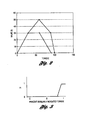
- the plot in Figure 2 compares the valve overlap calibration values using ETC versus those used when the throttle is mechanically linked with the accelerator pedal.
- the high value of valve overlap available with ETC results from the removal of the constraint that torque must follow throttle movement on a 1 to 1 basis. This results in better fuel economy and lower NOX.
- a temperature sensor 60 provides an air charge temperature input signal to the EEC 10 which is indicative of the temperature of the air charge entering intake manifold 58.
- a mass air flow meter 62 is provided for measuring mass air flow into the engine.
- Another temperature sensor 64 provides an engine coolant temperature input signal to the EEC 10 that is indicative of the temperature of coolant circulating through the engine coolant system generally indicated at 66.
- a pressure sensor may be included in the intake manifold 58 to measure barometric pressure or barometric pressure may be inferred as is well know in the art.
- the EEC module 10 comprises a central processing unit 70, a random-access memory (RAM) 72 for temporary data storage, a read-only memory (ROM) 74 for storing control programs, a keep-alive-memory (KAM) 76 for storing learned values, Input/Output ports 78 including the usual analog to digital and digital to analog converter, and a conventional data bus 80.
- RAM random-access memory
- ROM read-only memory
- KAM keep-alive-memory
- the EEC 10 receives the various input signals, and processes the data in accordance with a control program that preferably includes a camshaft timing subroutine for determining a desired timing of the camshafts 12 and 14 relative to the crankshaft 20.
- the control program also preferably includes a duty cycle calculation subroutine for computing separate correction signals activating the actuators 38 and 40 to correct the timing of the camshafts 12 and 14, respectively, to the desired relationship with the crankshaft 20, the position of which is determined from the CPS signal 52.
- the control program in the EEC 10 also provides output control signals to fuel control block 82 to control the amount of fuel injected by injectors within the engine, and ignition control block 84 to control the ignition timing of the air/fuel mixture within the combustion chambers of the engine.
- a preferred embodiment advantageously determines an intake valve closing (IVC) phase angle and valve overlap (OL) over the operating range of engine speed and indicated torque and generates camshaft position signals 42 and 44 as a function of the IVC and OL in order to optimize fuel economy, emissions and power at all altitudes, by executing the camshaft timing routine shown in Figure 4.
- the steps in Figure 4 are preferably executed by the EEC 10 in a background loop.
- the camshaft timing routine determines the operator desired engine indicated torque at block 100.
- Friction_torque table B(n,air_chg)+ accessory_loss
- peak indicated torque is preferably obtained from a ROM based calibration lookup table C, modified as indicated below for a given air charge temperature (act) and barometric pressure (bp).
- Peak_indicated_torque table C(n) * bp/29.92 * sqrt(560/(act+460)) where table C is a calibratable table of observed peak indicated torque at standard temperature 100 degrees Fahrenheit (37.8 degrees centigrade) and pressure 29.92 in.hg. (101.32 kN/m 2 ) at the optimal cam timings for power (OP) .
- Desired_percent_peak_indicated torque desired_indicated_torque peak_indicated_torque
- SL stability limited
- an intake valve closing (IVC) value in degrees, is obtained for the current engine speed and demanded indicated torque from an SL calibration table 1.
- Table1 is populated with IVC calibration values as a function of demanded indicated torque over the operating range of engine speed. Also in block 106, a valve overlap (OL) value, in degrees, is obtained for the current engine speed and demanded indicated torque from a SL calibration table2.
- OL valve overlap
- Table2 is populated with OL calibration values that are also a function of demanded indicated torque over the operating range of engine speed.
- an IVC value and a OL value are obtained respectively from ROM based calibration table3 and ROM based calibration table4. These tables represent timing values for optimal power (OP) and are populated with IVC and OL values as a function of engine speed only. The construction of an engine is such that a torque input is not required for table 3 and table 4.
- a power index is obtained from a ROM based lookup table5 populated with values from 0 to 1 in accordance with the chart of Figure 3.
- the PI represents the relative desire of the customer for economy or power and is obtained as a function of the percent of available indicated torque demanded by the vehicle operator as calculated in block 104.
- An operator demand of less than approximately 80% of the peak indicated torque available produces a PI of 0 indicative of a desire for economy.
- a PI of between approximately 0 and .9 are produced. Above approximately 90%, a PI of 1 is produced.
- the desired IVC and OL are calculated using the PI obtained from block 110 to interpolate between the values contained in the SL tables (table1 and table2) and the OP tables (table3 and table4).
- IVC and OL values are converted to other valve timing metrics.
- variable intake cam lift and/or variable exhaust cam lift A variable lift system would entail additional ROM based calibration lookup tables populated with values of lift.
- a pair of tables of stability limited lift as a function of engine speed and indicated torque, analogous to table 1 and table 2 and a pair of tables of optimum power lift as a function of engine speed, analogous to table 3 and table 4 would be used.
- the interpolation of optimal lift would utilize the PI of table5.
Landscapes
- Engineering & Computer Science (AREA)
- Mechanical Engineering (AREA)
- General Engineering & Computer Science (AREA)
- Chemical & Material Sciences (AREA)
- Combustion & Propulsion (AREA)
- Output Control And Ontrol Of Special Type Engine (AREA)
- Combined Controls Of Internal Combustion Engines (AREA)
Applications Claiming Priority (2)
| Application Number | Priority Date | Filing Date | Title |
|---|---|---|---|
| US09/737,383 US6371066B1 (en) | 2000-12-15 | 2000-12-15 | Torque based cam timing control method and system |
| US737383 | 2000-12-15 |
Publications (3)
| Publication Number | Publication Date |
|---|---|
| EP1245808A2 true EP1245808A2 (fr) | 2002-10-02 |
| EP1245808A3 EP1245808A3 (fr) | 2003-02-05 |
| EP1245808B1 EP1245808B1 (fr) | 2007-06-20 |
Family
ID=24963699
Family Applications (1)
| Application Number | Title | Priority Date | Filing Date |
|---|---|---|---|
| EP01000706A Expired - Lifetime EP1245808B1 (fr) | 2000-12-15 | 2001-12-04 | Commande et système de soupape en fonction du couple |
Country Status (3)
| Country | Link |
|---|---|
| US (1) | US6371066B1 (fr) |
| EP (1) | EP1245808B1 (fr) |
| DE (1) | DE60128997T2 (fr) |
Families Citing this family (12)
| Publication number | Priority date | Publication date | Assignee | Title |
|---|---|---|---|---|
| ITBO20010076A1 (it) * | 2001-02-13 | 2002-08-13 | Magneti Marelli Spa | Metodo per la stima del reperimento di un cilindro in un motore a combustione interna |
| JP2005133708A (ja) * | 2003-10-09 | 2005-05-26 | Denso Corp | バルブ特性調整装置 |
| WO2008024562A2 (fr) * | 2006-08-25 | 2008-02-28 | Borgwarner Inc | Solénoïde à force variable avec capteur de position intégré |
| US9002550B2 (en) * | 2007-07-02 | 2015-04-07 | GM Global Technology Operations LLC | Use of torque model at virtual engine conditions |
| JP4880556B2 (ja) * | 2007-09-27 | 2012-02-22 | 日立オートモティブシステムズ株式会社 | 可変動弁機構の制御装置 |
| KR100980865B1 (ko) | 2007-12-14 | 2010-09-10 | 기아자동차주식회사 | 가변 밸브 타이밍 기구 제어 방법 |
| DE102008046405B4 (de) * | 2008-01-14 | 2016-04-21 | GM Global Technology Operations LLC (n. d. Ges. d. Staates Delaware) | Drehmomentschätzsystem und -verfahren |
| JP4678545B2 (ja) * | 2008-07-25 | 2011-04-27 | 株式会社デンソー | モータ駆動装置 |
| DE102014204492A1 (de) * | 2014-03-12 | 2015-10-01 | Volkswagen Aktiengesellschaft | Kraftfahrzeug, Steuergerät und Verfahren zum Steuern einer Phasenlage einer Nockenwelle |
| JP6292276B1 (ja) * | 2016-10-19 | 2018-03-14 | マツダ株式会社 | エンジンの可変動弁装置 |
| KR102165878B1 (ko) * | 2020-01-20 | 2020-10-14 | 주식회사 현대케피코 | 인공신경망을 이용한 차량 엔진 토크 추정 방법 |
| SE544230C2 (en) * | 2020-03-26 | 2022-03-08 | Scania Cv Ab | Method and arrangement for variable valve timing for inernal combustion engine; vehicle and engine with such arrangement; computer program and computer readable medium for such a method |
Citations (2)
| Publication number | Priority date | Publication date | Assignee | Title |
|---|---|---|---|---|
| US5117784A (en) | 1991-05-03 | 1992-06-02 | Ford Motor Company | Internal combustion engine camshaft phaseshift control system |
| US5609126A (en) | 1994-10-03 | 1997-03-11 | Ford Motor Company | Variable camshaft timing system with altitude compensation |
Family Cites Families (13)
| Publication number | Priority date | Publication date | Assignee | Title |
|---|---|---|---|---|
| US4577592A (en) * | 1984-06-27 | 1986-03-25 | Bosch Henery G K | Self adjusting camshaft gear for internal combustion engines |
| US5009203A (en) | 1988-08-01 | 1991-04-23 | Honda Giken Kogyo Kabushiki Kaisha | Control method for valve-timing changeover in engine |
| JPH04143409A (ja) | 1990-10-03 | 1992-05-18 | Nissan Motor Co Ltd | 内燃機関の可変動弁装置 |
| JP2707832B2 (ja) | 1990-11-26 | 1998-02-04 | 日産自動車株式会社 | 内燃機関の出力制御装置 |
| JP2636498B2 (ja) | 1990-11-29 | 1997-07-30 | 日産自動車株式会社 | エンジンの制御装置 |
| JP2905612B2 (ja) | 1991-03-28 | 1999-06-14 | マツダ株式会社 | エンジンのバルブタイミング制御装置 |
| JP2585898B2 (ja) * | 1991-07-29 | 1997-02-26 | 本田技研工業株式会社 | 内燃エンジンの空燃比制御装置 |
| JP3385717B2 (ja) | 1994-05-02 | 2003-03-10 | 日産自動車株式会社 | 内燃機関の可変動弁装置 |
| JP3123398B2 (ja) | 1995-07-26 | 2001-01-09 | トヨタ自動車株式会社 | 内燃機関の連続可変バルブタイミング制御装置 |
| JPH0979056A (ja) * | 1995-09-12 | 1997-03-25 | Toyota Motor Corp | 内燃機関のバルブタイミング制御装置 |
| US5680834A (en) | 1996-01-22 | 1997-10-28 | Ford Global Technologies, Inc. | Just-in-time scheduling for variable camshaft timing |
| US6006725A (en) | 1998-01-12 | 1999-12-28 | Ford Global Technologies, Inc. | System and method for controlling camshaft timing, air/fuel ratio, and throttle position in an automotive internal combustion engine |
| US5957096A (en) | 1998-06-09 | 1999-09-28 | Ford Global Technologies, Inc. | Internal combustion engine with variable camshaft timing, charge motion control valve, and variable air/fuel ratio |
-
2000
- 2000-12-15 US US09/737,383 patent/US6371066B1/en not_active Expired - Lifetime
-
2001
- 2001-12-04 EP EP01000706A patent/EP1245808B1/fr not_active Expired - Lifetime
- 2001-12-04 DE DE60128997T patent/DE60128997T2/de not_active Expired - Lifetime
Patent Citations (2)
| Publication number | Priority date | Publication date | Assignee | Title |
|---|---|---|---|---|
| US5117784A (en) | 1991-05-03 | 1992-06-02 | Ford Motor Company | Internal combustion engine camshaft phaseshift control system |
| US5609126A (en) | 1994-10-03 | 1997-03-11 | Ford Motor Company | Variable camshaft timing system with altitude compensation |
Also Published As
| Publication number | Publication date |
|---|---|
| DE60128997D1 (de) | 2007-08-02 |
| DE60128997T2 (de) | 2008-02-21 |
| US6371066B1 (en) | 2002-04-16 |
| EP1245808A3 (fr) | 2003-02-05 |
| EP1245808B1 (fr) | 2007-06-20 |
Similar Documents
| Publication | Publication Date | Title |
|---|---|---|
| EP1227229B1 (fr) | Méthode et système pour faire fonctionner un moteur à combustion interne à nombre de cylindres variable | |
| US8954257B2 (en) | Coordinated torque control security systems and methods | |
| US7324889B2 (en) | Intake-air quantity control system of engine | |
| JP3837819B2 (ja) | 内燃機関用バルブタイミング制御装置 | |
| US20140074373A1 (en) | Coordinated engine torque control | |
| US8886440B2 (en) | Method and system for reducing turbo lag in an engine | |
| EP1245808B1 (fr) | Commande et système de soupape en fonction du couple | |
| US5609126A (en) | Variable camshaft timing system with altitude compensation | |
| JP3085181B2 (ja) | 内燃機関の点火時期制御装置 | |
| US6564785B2 (en) | Cylinder intake-air quantity calculating apparatus and method for internal combustion engine | |
| US7198029B1 (en) | Extension of DOD operation in torque control system | |
| US6966287B1 (en) | CAM phaser and DOD coordination for engine torque control | |
| US6460508B1 (en) | Method of operation for an internal combustion engine | |
| JPH0968078A (ja) | 内燃機関の燃料噴射量制御装置 | |
| EP0980973B1 (fr) | Dispositif de commande d'injection de carburant pour moteur à combustion interne | |
| US8000875B2 (en) | Method and device as well as computer program for controlling an internal combustion engine | |
| WO2007129168A1 (fr) | Appareil de régulation pour moteur à combustion interne | |
| US6539919B2 (en) | Ignition timing for engine with dual independent camshafts | |
| US7353788B2 (en) | Fuzzy logic based cam phaser control | |
| JP2003522896A (ja) | 内燃機関を制御する方法 | |
| US7209825B2 (en) | Control apparatus for internal combustion engine | |
| US10563595B2 (en) | Control device of internal combustion engine | |
| JP2004124743A (ja) | 内燃機関用制御装置 | |
| US8141539B2 (en) | Controller and control method for internal combustion engine | |
| JPH0972225A (ja) | 連続可変式バルブタイミング制御装置 |
Legal Events
| Date | Code | Title | Description |
|---|---|---|---|
| PUAI | Public reference made under article 153(3) epc to a published international application that has entered the european phase |
Free format text: ORIGINAL CODE: 0009012 |
|
| AK | Designated contracting states |
Kind code of ref document: A2 Designated state(s): AT BE CH CY DE DK ES FI FR GB GR IE IT LI LU MC NL PT SE TR |
|
| AX | Request for extension of the european patent |
Free format text: AL;LT;LV;MK;RO;SI |
|
| PUAL | Search report despatched |
Free format text: ORIGINAL CODE: 0009013 |
|
| AK | Designated contracting states |
Designated state(s): AT BE CH CY DE DK ES FI FR GB GR IE IT LI LU MC NL PT SE TR |
|
| AX | Request for extension of the european patent |
Extension state: AL LT LV MK RO SI |
|
| RIC1 | Information provided on ipc code assigned before grant |
Ipc: 7F 01L 1/34 B Ipc: 7F 02D 13/02 A Ipc: 7F 02D 41/24 B Ipc: 7F 01L 1/344 B |
|
| 17P | Request for examination filed |
Effective date: 20030716 |
|
| AKX | Designation fees paid |
Designated state(s): DE GB SE |
|
| GRAP | Despatch of communication of intention to grant a patent |
Free format text: ORIGINAL CODE: EPIDOSNIGR1 |
|
| GRAS | Grant fee paid |
Free format text: ORIGINAL CODE: EPIDOSNIGR3 |
|
| GRAA | (expected) grant |
Free format text: ORIGINAL CODE: 0009210 |
|
| RAP1 | Party data changed (applicant data changed or rights of an application transferred) |
Owner name: FORD GLOBAL TECHNOLOGIES, LLC |
|
| AK | Designated contracting states |
Kind code of ref document: B1 Designated state(s): DE GB SE |
|
| REG | Reference to a national code |
Ref country code: GB Ref legal event code: FG4D |
|
| REF | Corresponds to: |
Ref document number: 60128997 Country of ref document: DE Date of ref document: 20070802 Kind code of ref document: P |
|
| REG | Reference to a national code |
Ref country code: SE Ref legal event code: TRGR |
|
| PLBE | No opposition filed within time limit |
Free format text: ORIGINAL CODE: 0009261 |
|
| STAA | Information on the status of an ep patent application or granted ep patent |
Free format text: STATUS: NO OPPOSITION FILED WITHIN TIME LIMIT |
|
| 26N | No opposition filed |
Effective date: 20080325 |
|
| REG | Reference to a national code |
Ref country code: DE Ref legal event code: R082 Ref document number: 60128997 Country of ref document: DE Representative=s name: DOERFLER, THOMAS, DR.-ING., DE |
|
| PGFP | Annual fee paid to national office [announced via postgrant information from national office to epo] |
Ref country code: GB Payment date: 20171128 Year of fee payment: 17 Ref country code: SE Payment date: 20171208 Year of fee payment: 17 |
|
| REG | Reference to a national code |
Ref country code: SE Ref legal event code: EUG |
|
| PG25 | Lapsed in a contracting state [announced via postgrant information from national office to epo] |
Ref country code: SE Free format text: LAPSE BECAUSE OF NON-PAYMENT OF DUE FEES Effective date: 20181205 |
|
| GBPC | Gb: european patent ceased through non-payment of renewal fee |
Effective date: 20181204 |
|
| PG25 | Lapsed in a contracting state [announced via postgrant information from national office to epo] |
Ref country code: GB Free format text: LAPSE BECAUSE OF NON-PAYMENT OF DUE FEES Effective date: 20181204 |
|
| PGFP | Annual fee paid to national office [announced via postgrant information from national office to epo] |
Ref country code: DE Payment date: 20201112 Year of fee payment: 20 |
|
| REG | Reference to a national code |
Ref country code: DE Ref legal event code: R071 Ref document number: 60128997 Country of ref document: DE |