EP1245882A2 - Valve de gonflage pour la jante d'un pneumatique pour un véhicule - Google Patents
Valve de gonflage pour la jante d'un pneumatique pour un véhicule Download PDFInfo
- Publication number
- EP1245882A2 EP1245882A2 EP20020005103 EP02005103A EP1245882A2 EP 1245882 A2 EP1245882 A2 EP 1245882A2 EP 20020005103 EP20020005103 EP 20020005103 EP 02005103 A EP02005103 A EP 02005103A EP 1245882 A2 EP1245882 A2 EP 1245882A2
- Authority
- EP
- European Patent Office
- Prior art keywords
- piston
- tire
- valve body
- valve
- valve according
- Prior art date
- Legal status (The legal status is an assumption and is not a legal conclusion. Google has not performed a legal analysis and makes no representation as to the accuracy of the status listed.)
- Withdrawn
Links
- 239000000463 material Substances 0.000 claims abstract description 8
- 239000007769 metal material Substances 0.000 claims abstract description 4
- 238000007789 sealing Methods 0.000 claims description 8
- 239000011324 bead Substances 0.000 claims description 5
- 230000006835 compression Effects 0.000 claims description 3
- 238000007906 compression Methods 0.000 claims description 3
- 238000012544 monitoring process Methods 0.000 claims description 3
- 230000002093 peripheral effect Effects 0.000 claims description 3
- 230000007547 defect Effects 0.000 description 2
- 230000002349 favourable effect Effects 0.000 description 2
- 230000009286 beneficial effect Effects 0.000 description 1
- 239000013013 elastic material Substances 0.000 description 1
- 238000009434 installation Methods 0.000 description 1
Images

Classifications
-
- F—MECHANICAL ENGINEERING; LIGHTING; HEATING; WEAPONS; BLASTING
- F16—ENGINEERING ELEMENTS AND UNITS; GENERAL MEASURES FOR PRODUCING AND MAINTAINING EFFECTIVE FUNCTIONING OF MACHINES OR INSTALLATIONS; THERMAL INSULATION IN GENERAL
- F16K—VALVES; TAPS; COCKS; ACTUATING-FLOATS; DEVICES FOR VENTING OR AERATING
- F16K15/00—Check valves
- F16K15/20—Check valves specially designed for inflatable bodies, e.g. tyres
- F16K15/207—Check valves specially designed for inflatable bodies, e.g. tyres and combined with other valves, e.g. safety valves
-
- B—PERFORMING OPERATIONS; TRANSPORTING
- B60—VEHICLES IN GENERAL
- B60C—VEHICLE TYRES; TYRE INFLATION; TYRE CHANGING; CONNECTING VALVES TO INFLATABLE ELASTIC BODIES IN GENERAL; DEVICES OR ARRANGEMENTS RELATED TO TYRES
- B60C29/00—Arrangements of tyre-inflating valves to tyres or rims; Accessories for tyre-inflating valves, not otherwise provided for
- B60C29/007—Arrangements of tyre-inflating valves to tyres or rims; Accessories for tyre-inflating valves, not otherwise provided for for tyres with segmental sections or for multi-chamber tyres
-
- Y—GENERAL TAGGING OF NEW TECHNOLOGICAL DEVELOPMENTS; GENERAL TAGGING OF CROSS-SECTIONAL TECHNOLOGIES SPANNING OVER SEVERAL SECTIONS OF THE IPC; TECHNICAL SUBJECTS COVERED BY FORMER USPC CROSS-REFERENCE ART COLLECTIONS [XRACs] AND DIGESTS
- Y10—TECHNICAL SUBJECTS COVERED BY FORMER USPC
- Y10T—TECHNICAL SUBJECTS COVERED BY FORMER US CLASSIFICATION
- Y10T137/00—Fluid handling
- Y10T137/2496—Self-proportioning or correlating systems
- Y10T137/2559—Self-controlled branched flow systems
- Y10T137/265—Plural outflows
- Y10T137/2668—Alternately or successively substituted outflow
- Y10T137/2693—Pressure responsive
-
- Y—GENERAL TAGGING OF NEW TECHNOLOGICAL DEVELOPMENTS; GENERAL TAGGING OF CROSS-SECTIONAL TECHNOLOGIES SPANNING OVER SEVERAL SECTIONS OF THE IPC; TECHNICAL SUBJECTS COVERED BY FORMER USPC CROSS-REFERENCE ART COLLECTIONS [XRACs] AND DIGESTS
- Y10—TECHNICAL SUBJECTS COVERED BY FORMER USPC
- Y10T—TECHNICAL SUBJECTS COVERED BY FORMER US CLASSIFICATION
- Y10T137/00—Fluid handling
- Y10T137/3584—Inflatable article [e.g., tire filling chuck and/or stem]
- Y10T137/36—With pressure-responsive pressure-control means
Definitions
- the invention relates to a tire valve for the rim of a Pneumatic tire on a vehicle with a valve body a rigid material and with a valve insert and at a distance from this intended air outlet of a flow path.
- Such a tire valve is the document for DE 200 15 467 Can be seen in U1.
- the intermediate tube lies at one end of a hollow shaft of the valve body clamps and surrounds the other the spaced adjacent end region of the valve sleeve.
- the mouth of that longitudinal hole is a ring shoulder on one arranged axially bounding head tube of a hollow shaft.
- the valve body is at least partially by one Surround screw sleeve, which is at a radial distance from one
- the outer bulge of the hollow shaft runs along with this one Clamping pair for the intermediate tube forms.
- a ring made of elastic material as an investment element for the rim; between the lower edge of the screw sleeve and the elastic ring is a ring disc made of rigid material intended.
- the metallic valve body one Valve insert contains and at a distance from the rim on one Valve cap ends. Thanks to an external thread, the valve body take a screw sleeve between the and that ring shoulder of the molded valve foot the rim is pinched.
- This tire valve ends within the Rim in a signal housing, the two foot elements to put on on the rim well as for adjustable storage in assembled state.
- a connecting element between Tire valve and signal housing serves a hollow, in the valve bore of the - with the ring shoulder a seat in the signal housing - tire valve engaging screw, whose head adjoins the valve Side of a longitudinal wall of the Signal housing creates.
- the commercial vehicle sector is looking for a usable replacement wanted for the twin tires on the drive axle, for example by using so-called "SuperSingle” tires.
- the runflat system is also said to be air-filled Safety hose to be installed, thanks to that in the event of a tire defect, continue driving on this safety system remains possible.
- the filling of two separate air volumes required is also said to be air-filled Safety hose to be installed, thanks to that in the event of a tire defect, continue driving on this safety system remains possible.
- each is the Air outlets in a separately sealed area of the Interior of the valve body arranged, and the mouth the piston-side flow path is thanks to the relative movement either one of the pistons and the valve body Assigned areas. It has proven to be beneficial from the piston or slide on the one hand and the surrounding area Valve body, on the other hand, one parallel to the piston axis To form a gap that runs across the direction of movement of the piston - sealing elements in divided the individual areas for the air outlets becomes.
- the sealing elements are preferably in the grooves Inner surface of the wall of the valve body at an axial distance inserted and protruding from each other 0-rings, where the - containing the mouth of the flow path - Tangential circumferential surface or itself is cuddled along, that mouth of the Flow path is moved within the valve body.
- the wall of the valve body is preferably cross-sectional oval or cylindrical, and the shape of the piston - At least from the sealing elements or 0-rings assigned section - will encompass that section Cross section adapted; the piston can according to the invention a piston body adapted to the cross section of the valve body have and a axially projecting from this Valve insert containing - axial tube of smaller cross section.
- the flow path of the piston or spool should pass through the Interior of the axial tube - as continuing in the piston body and closed to the bottom surface of the axial Pipe channel of the valve insert equipped at the free end Axialrohres - as well as one of this pipe channel outgoing radial bore are formed.
- a base plate integral with the wall of the valve body Always keep a distance from the base plate on the inside at least one stop element for the bottom surface of the piston or the piston body, however is of relatively low height.
- the piston body is at a distance to the stop element and the mouth of the flow path from pipe channel and radial bore in another area the gap faces an air outlet, which is connected to the tire interior; to the air outlet is a device for tire pressure monitoring connected, such as the DE 296 23 466 Applicant can be seen.
- the setting of the piston body is used on his Head area of stored energy store, which is different supported on a fixed counter surface.
- a coil spring can act as an energy store for the axial tube embrace the other in a receiving space of a clamping nut outsourced.
- the counter surface or the clamping nut is through an internal thread of the valve body in its interior held, and the distance of the clamping nut from the base plate the valve body is adjustable.
- valve body there is an external thread for an external nut which with a radially protruding bead body of the valve body a clamping device for fixing it to the mentioned Rim forms.
- This bead body is intended to be a radial stop surface offer that one directed to the outer mother Sealing element - preferably an O-ring - contains.
- This invention ensures that always first the safety hose is filled.
- the lower exit is via a flexible connection with the actual Safety hose connected and is thus when inflating filled.
- a certain pressure - for example 9.5 Bar - is reached, the piston is against the spring force moved to the top position and the air passage to the tire open towards.
- any air pressure can be set. Once the Air pressure in the safety hose under the above the specified value falls, the valve switches to the connection position to the safety hose so that when refilling in any case, this first on the prescribed Pressure value is filled up and only then "Super Single".
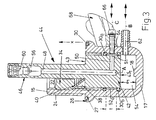
- the external thread 24 meshes with a polygonal nut 32, the with that stop surface 26 or its O-ring 30 one Clamping device for fixing the tire valve 12 forms.
- a clamping nut 34 of height h screwed which is penetrated by an axial channel 36 and towards the bottom plate 17 a cylindrical receiving space 38 for a conical tapering out of it Compression spring 40 contains.
- an - adapted cylindrical - piston body 42 of a piston or slide 44 Arranged in the lower region of the valve interior 20 is an - adapted cylindrical - piston body 42 of a piston or slide 44, on the top surface 43 of which is loaded the spiral or compression spring 40 which surrounds an axial tube 46 of the slide 44 which projects from the top surface 43.
- This axial tube 46 of length q passes through the axial channel 36 of the clamping nut 34 and protrudes from the valve body 14 with a protruding length q 1 , even if - in the vented state shown in FIGS. 1, 2 - the bottom surface 43 t of the piston body 42 is seated on the stop pin 18 of the base plate 17.
- the pipe channel 48 falling into the cylinder axis A continues in the subsequent piston body 42 and ends at a small distance n 1 from the bottom surface 43 t .
- a radial bore 50 extends from the latter, the opening 51 of which is provided on the peripheral surface 41 of the piston body 42.
- This peripheral surface 41 delimits with the opposite inner surface of the wall 16 an annular space 52, of which an upper portion 52 a of length t is delimited by two O-rings 30 a , 30 b .
- This length t is shorter than half the height n of the piston body 42.
- the lower O-ring 30 b delimits a lower annular space section 52 b , which merges into a floor space 54 surrounding the stop pin 18.
- valve insert 60 provided, designed for example according to DIN 7757, in an expansion of the cavity forming a cavity 56 Pipe channel 48 ends.
- the tire valve 12 is intended for a tire that is as Emergency running system also an air-filled safety hose contains to continue driving in the event of a tire defect to allow on this security system. The filling of these two separate air volumes is said to described valve 12 take place.
Landscapes
- Engineering & Computer Science (AREA)
- General Engineering & Computer Science (AREA)
- Mechanical Engineering (AREA)
- Check Valves (AREA)
- Tires In General (AREA)
Applications Claiming Priority (4)
| Application Number | Priority Date | Filing Date | Title |
|---|---|---|---|
| DE20105319U | 2001-03-26 | ||
| DE20105319 | 2001-03-26 | ||
| DE20108389U DE20108389U1 (de) | 2001-03-26 | 2001-05-18 | Reifenventil für die Felge eines Luftreifens an einem Fahrzeug |
| DE20108389U | 2001-05-18 |
Publications (2)
| Publication Number | Publication Date |
|---|---|
| EP1245882A2 true EP1245882A2 (fr) | 2002-10-02 |
| EP1245882A3 EP1245882A3 (fr) | 2003-06-18 |
Family
ID=26056888
Family Applications (1)
| Application Number | Title | Priority Date | Filing Date |
|---|---|---|---|
| EP20020005103 Withdrawn EP1245882A3 (fr) | 2001-03-26 | 2002-03-07 | Valve de gonflage pour la jante d'un pneumatique pour un véhicule |
Country Status (2)
| Country | Link |
|---|---|
| US (1) | US6918403B2 (fr) |
| EP (1) | EP1245882A3 (fr) |
Families Citing this family (20)
| Publication number | Priority date | Publication date | Assignee | Title |
|---|---|---|---|---|
| US6604414B1 (en) * | 2001-12-04 | 2003-08-12 | Dana Corporation | Supply and tire pressure sensing apparatus and method |
| US6772812B1 (en) * | 2003-03-25 | 2004-08-10 | Autoliv Asp, Inc. | Dual-function tire inlet valve |
| WO2007016204A2 (fr) * | 2005-07-27 | 2007-02-08 | Sagittarius Sporting Goods, Co. Ltd. | Rampe de gonflage |
| CN200988401Y (zh) * | 2006-11-29 | 2007-12-12 | 上海保隆汽车科技股份有限公司 | 一种无级可调胎压监测传感器信号盒的组合装置 |
| CN200988402Y (zh) * | 2006-12-04 | 2007-12-12 | 上海保隆汽车科技股份有限公司 | 一种有级可调胎压监测传感器信号盒的组合装置 |
| GB2446213B (en) * | 2007-01-31 | 2012-02-22 | Bf1Systems Ltd | A wheel sensor |
| JP5496555B2 (ja) * | 2009-06-23 | 2014-05-21 | 株式会社不二工機 | ユニットクーラーの洗浄装置 |
| CN101806369B (zh) * | 2010-04-02 | 2012-04-25 | 武汉元丰汽车技术发展有限公司 | 汽车轮胎中央充放气系统充放气阀总成 |
| EP2872344B1 (fr) * | 2012-07-13 | 2019-06-12 | Dana Heavy Vehicle Systems Group, LLC | Ensembles valve et procédés de gonflage et de dégonflage d'un pneumatique |
| US10259272B2 (en) | 2014-01-03 | 2019-04-16 | Dana Heavy Vehicle Systems Group, Llc | Assembly for a central tire inflation system |
| CN106457938B (zh) * | 2014-04-16 | 2018-04-06 | 录制股份公司 | 空气室用阀 |
| EP3160776A1 (fr) | 2014-06-30 | 2017-05-03 | Dana Heavy Vehicle Systems Group, LLC | Ensemble valve pour un système de gestion de pression de pneu |
| US9533534B2 (en) | 2014-10-22 | 2017-01-03 | The Goodyear Tire & Rubber Company | Air maintenance tire and valve assembly and method |
| WO2017024216A1 (fr) | 2015-08-06 | 2017-02-09 | Dana Heavy Vehicle Systems Group, Llc | Ensemble valve pour un système de gestion de la pression des pneus |
| DE112016003576T5 (de) | 2015-08-06 | 2018-05-03 | Dana Heavy Vehicle Systems Group, Llc | Steuer- und zuführungsventilandordnung für ein reifendruck-managementsystem |
| US10214059B2 (en) | 2015-10-16 | 2019-02-26 | Dana Heavy Vehicle Systems Group, Llc | Tire pressure management system and method of decreasing tire pressure |
| EP3368136B1 (fr) * | 2015-10-29 | 2025-08-06 | ConvaTec Technologies Inc. | Système de soupape pour dispositifs gonflables |
| US9688108B1 (en) | 2015-12-03 | 2017-06-27 | The Goodyear Tire & Rubber Company | Dual tire air maintenance system and method |
| US10864783B2 (en) | 2016-01-29 | 2020-12-15 | Dana Heavy Vehicle Systems Group, Llc | Valve assembly for a tire inflation system |
| US10703149B2 (en) * | 2017-06-27 | 2020-07-07 | CushCore Inc. | Air valve for tubeless pneumatic tire |
Citations (2)
| Publication number | Priority date | Publication date | Assignee | Title |
|---|---|---|---|---|
| EP0751017B1 (fr) | 1995-06-26 | 1999-09-01 | Alligator Ventilfabrik GmbH | Dispositif pour mesurer la pression d'un pneumatique d'un véhicule |
| DE20015467U1 (de) | 2000-08-22 | 2001-01-04 | Alligator Ventilfabrik GmbH, 89537 Giengen | Reifenventil für die Felge eines Luftreifens an einem Fahrzeug |
Family Cites Families (12)
| Publication number | Priority date | Publication date | Assignee | Title |
|---|---|---|---|---|
| CH20320A (de) * | 1899-09-12 | 1901-01-15 | Carl Schirp | Vorrichtung an Lufteinlaßventilen für Rad-Luftreifen mit zwei ineinander angeordneten Luftschläuchen, welche eine Füllung beider Luftschläuche durch einen Stutzen ermöglicht |
| US1729469A (en) * | 1926-01-26 | 1929-09-24 | Martin E Anderson | Air valve |
| US2167398A (en) * | 1936-07-06 | 1939-07-25 | Ira I Tubbs | Pneumatic tire |
| US2122740A (en) * | 1937-05-22 | 1938-07-05 | Alfred E Eckenroth | Valve stem |
| US2969824A (en) * | 1956-05-16 | 1961-01-31 | Frank A Howard | Safety pneumatic tire |
| US3065763A (en) * | 1960-07-13 | 1962-11-27 | Frank A Howard | Elastomer plug dual valve |
| US3331384A (en) * | 1964-06-29 | 1967-07-18 | Gen Electric | Automatic sequential valve |
| US3536119A (en) * | 1967-12-20 | 1970-10-27 | Nat Distillers Chem Corp | Dual valve for pneumatic tires |
| US3911988A (en) * | 1974-02-21 | 1975-10-14 | Eaton Corp | Pressurization control device |
| US4051767A (en) * | 1975-07-17 | 1977-10-04 | Dieter Landsberg | Actuator for fluid pressure-operated power devices |
| SU638498A1 (ru) * | 1976-03-18 | 1978-12-25 | Solovev Valerij A | Автоматический вентиль соловьева в.а. дл многосекционной камеры пневматической шины |
| DE3711785A1 (de) * | 1987-04-08 | 1988-10-27 | Gerd Ziegler | Sicherheitsluftreifen |
-
2002
- 2002-03-07 EP EP20020005103 patent/EP1245882A3/fr not_active Withdrawn
- 2002-03-25 US US10/106,553 patent/US6918403B2/en not_active Expired - Fee Related
Patent Citations (2)
| Publication number | Priority date | Publication date | Assignee | Title |
|---|---|---|---|---|
| EP0751017B1 (fr) | 1995-06-26 | 1999-09-01 | Alligator Ventilfabrik GmbH | Dispositif pour mesurer la pression d'un pneumatique d'un véhicule |
| DE20015467U1 (de) | 2000-08-22 | 2001-01-04 | Alligator Ventilfabrik GmbH, 89537 Giengen | Reifenventil für die Felge eines Luftreifens an einem Fahrzeug |
Also Published As
| Publication number | Publication date |
|---|---|
| EP1245882A3 (fr) | 2003-06-18 |
| US6918403B2 (en) | 2005-07-19 |
| US20020134428A1 (en) | 2002-09-26 |
Similar Documents
| Publication | Publication Date | Title |
|---|---|---|
| EP1245882A2 (fr) | Valve de gonflage pour la jante d'un pneumatique pour un véhicule | |
| DE102022125953A1 (de) | Absenkbare fahrradsattelstützstange mit einer schmalen gasfederpatrone | |
| DE845453C (de) | Mit einem hydraulischen Stossdaempfer vereinigte Luftfederung, insbesondere fuer Kraftfahrzeuge | |
| DE102022125949A1 (de) | Federpatronenanordnung mit niedrigem ölstand für fahrradsattelstütze | |
| DE60016952T2 (de) | Integrierte konsole und endverschlussplatte für eine luftfeder | |
| DE19731139C2 (de) | Kolben-Zylinder-Aggregat, das zwischen einem Aufbau und einem Radführungsteil eines Fahrzeugs eingebaut ist | |
| DE2839220A1 (de) | Fahrzeugradeinheit | |
| DE2813742A1 (de) | Ventil fuer luftreifen | |
| EP1182061A2 (fr) | Valve de gonflage pour la jante d'un pneumatique pour un véhicule | |
| DE202004015412U1 (de) | Zur Hubbegrenzung dienende, verstellbare Anschlaganordnung für eine Kolben-Zylinder-Einheit | |
| EP1232929B1 (fr) | Colonne de direction de sécurité | |
| DE60222971T2 (de) | Sicherheitsvorrichtung zur Befüllung einer Hülle, die platzen kann | |
| DE102015010055A1 (de) | Hydraulikzylinder, insbesondere Nehmerzylinder für eine hydraulische Kupplungsbetätigung für Kraftfahrzeuge | |
| DE2219097A1 (de) | Druckanzeiger für Luftreifen | |
| WO2018036969A1 (fr) | Alimentation en air d'un ressort pneumatique d'un véhicule ferroviaire | |
| DE20108389U1 (de) | Reifenventil für die Felge eines Luftreifens an einem Fahrzeug | |
| DE602004001067T2 (de) | Antriebseinheiten und Antriebsvorrichtungen | |
| DE8812996U1 (de) | Ventil für die Kontrolle des Reifendrucks | |
| DE1077074B (de) | Steuereinrichtung zur pneumatischen Abfederung eines Fahrzeugs | |
| AT509798B1 (de) | Modulare schlauchbrücke | |
| EP3231941B1 (fr) | Système de poteau | |
| CH687262A5 (de) | In Beton eingiessbares Einzelteil einer Schubdornverbindungsanordnung. | |
| EP1367287B1 (fr) | Amortisseur hydraulique | |
| EP1275532A1 (fr) | Valve de gonflage pour un pneumatique comprenant une chambre à air pour roulage à plat | |
| EP2284041A1 (fr) | Fixation de marche |
Legal Events
| Date | Code | Title | Description |
|---|---|---|---|
| PUAI | Public reference made under article 153(3) epc to a published international application that has entered the european phase |
Free format text: ORIGINAL CODE: 0009012 |
|
| AK | Designated contracting states |
Kind code of ref document: A2 Designated state(s): AT BE CH CY DE DK ES FI FR GB GR IE IT LI LU MC NL PT SE TR |
|
| AX | Request for extension of the european patent |
Free format text: AL;LT;LV;MK;RO;SI |
|
| PUAL | Search report despatched |
Free format text: ORIGINAL CODE: 0009013 |
|
| AK | Designated contracting states |
Designated state(s): AT BE CH CY DE DK ES FI FR GB GR IE IT LI LU MC NL PT SE TR |
|
| AX | Request for extension of the european patent |
Extension state: AL LT LV MK RO SI |
|
| 17P | Request for examination filed |
Effective date: 20031204 |
|
| AKX | Designation fees paid |
Designated state(s): DE ES FR GB IT |
|
| 17Q | First examination report despatched |
Effective date: 20060907 |
|
| STAA | Information on the status of an ep patent application or granted ep patent |
Free format text: STATUS: THE APPLICATION IS DEEMED TO BE WITHDRAWN |
|
| 18D | Application deemed to be withdrawn |
Effective date: 20070118 |