EP1247666B1 - Echangeur de chaleur et appareil de chauffage ou climatisation de voiture comprenant un tel échangeur de chaleur - Google Patents
Echangeur de chaleur et appareil de chauffage ou climatisation de voiture comprenant un tel échangeur de chaleur Download PDFInfo
- Publication number
- EP1247666B1 EP1247666B1 EP02004904A EP02004904A EP1247666B1 EP 1247666 B1 EP1247666 B1 EP 1247666B1 EP 02004904 A EP02004904 A EP 02004904A EP 02004904 A EP02004904 A EP 02004904A EP 1247666 B1 EP1247666 B1 EP 1247666B1
- Authority
- EP
- European Patent Office
- Prior art keywords
- heat exchanger
- discs
- flow passages
- exchanger according
- medium
- Prior art date
- Legal status (The legal status is an assumption and is not a legal conclusion. Google has not performed a legal analysis and makes no representation as to the accuracy of the status listed.)
- Expired - Lifetime
Links
Images




Classifications
-
- F—MECHANICAL ENGINEERING; LIGHTING; HEATING; WEAPONS; BLASTING
- F28—HEAT EXCHANGE IN GENERAL
- F28F—DETAILS OF HEAT-EXCHANGE AND HEAT-TRANSFER APPARATUS, OF GENERAL APPLICATION
- F28F17/00—Removing ice or water from heat-exchange apparatus
- F28F17/005—Means for draining condensates from heat exchangers, e.g. from evaporators
-
- B—PERFORMING OPERATIONS; TRANSPORTING
- B60—VEHICLES IN GENERAL
- B60H—ARRANGEMENTS OF HEATING, COOLING, VENTILATING OR OTHER AIR-TREATING DEVICES SPECIALLY ADAPTED FOR PASSENGER OR GOODS SPACES OF VEHICLES
- B60H1/00—Heating, cooling or ventilating devices
- B60H1/00321—Heat exchangers for air-conditioning devices
- B60H1/00328—Heat exchangers for air-conditioning devices of the liquid-air type
-
- F—MECHANICAL ENGINEERING; LIGHTING; HEATING; WEAPONS; BLASTING
- F28—HEAT EXCHANGE IN GENERAL
- F28D—HEAT-EXCHANGE APPARATUS, NOT PROVIDED FOR IN ANOTHER SUBCLASS, IN WHICH THE HEAT-EXCHANGE MEDIA DO NOT COME INTO DIRECT CONTACT
- F28D1/00—Heat-exchange apparatus having stationary conduit assemblies for one heat-exchange medium only, the media being in contact with different sides of the conduit wall, in which the other heat-exchange medium is a large body of fluid, e.g. domestic or motor car radiators
- F28D1/02—Heat-exchange apparatus having stationary conduit assemblies for one heat-exchange medium only, the media being in contact with different sides of the conduit wall, in which the other heat-exchange medium is a large body of fluid, e.g. domestic or motor car radiators with heat-exchange conduits immersed in the body of fluid
- F28D1/03—Heat-exchange apparatus having stationary conduit assemblies for one heat-exchange medium only, the media being in contact with different sides of the conduit wall, in which the other heat-exchange medium is a large body of fluid, e.g. domestic or motor car radiators with heat-exchange conduits immersed in the body of fluid with plate-like or laminated conduits
- F28D1/0308—Heat-exchange apparatus having stationary conduit assemblies for one heat-exchange medium only, the media being in contact with different sides of the conduit wall, in which the other heat-exchange medium is a large body of fluid, e.g. domestic or motor car radiators with heat-exchange conduits immersed in the body of fluid with plate-like or laminated conduits the conduits being formed by paired plates touching each other
- F28D1/0325—Heat-exchange apparatus having stationary conduit assemblies for one heat-exchange medium only, the media being in contact with different sides of the conduit wall, in which the other heat-exchange medium is a large body of fluid, e.g. domestic or motor car radiators with heat-exchange conduits immersed in the body of fluid with plate-like or laminated conduits the conduits being formed by paired plates touching each other the plates having lateral openings therein for circulation of the heat-exchange medium from one conduit to another
- F28D1/0333—Heat-exchange apparatus having stationary conduit assemblies for one heat-exchange medium only, the media being in contact with different sides of the conduit wall, in which the other heat-exchange medium is a large body of fluid, e.g. domestic or motor car radiators with heat-exchange conduits immersed in the body of fluid with plate-like or laminated conduits the conduits being formed by paired plates touching each other the plates having lateral openings therein for circulation of the heat-exchange medium from one conduit to another the plates having integrated connecting members
-
- F—MECHANICAL ENGINEERING; LIGHTING; HEATING; WEAPONS; BLASTING
- F28—HEAT EXCHANGE IN GENERAL
- F28D—HEAT-EXCHANGE APPARATUS, NOT PROVIDED FOR IN ANOTHER SUBCLASS, IN WHICH THE HEAT-EXCHANGE MEDIA DO NOT COME INTO DIRECT CONTACT
- F28D9/00—Heat-exchange apparatus having stationary plate-like or laminated conduit assemblies for both heat-exchange media, the media being in contact with different sides of a conduit wall
- F28D9/0031—Heat-exchange apparatus having stationary plate-like or laminated conduit assemblies for both heat-exchange media, the media being in contact with different sides of a conduit wall the conduits for one heat-exchange medium being formed by paired plates touching each other
- F28D9/0037—Heat-exchange apparatus having stationary plate-like or laminated conduit assemblies for both heat-exchange media, the media being in contact with different sides of a conduit wall the conduits for one heat-exchange medium being formed by paired plates touching each other the conduits for the other heat-exchange medium also being formed by paired plates touching each other
-
- F—MECHANICAL ENGINEERING; LIGHTING; HEATING; WEAPONS; BLASTING
- F28—HEAT EXCHANGE IN GENERAL
- F28F—DETAILS OF HEAT-EXCHANGE AND HEAT-TRANSFER APPARATUS, OF GENERAL APPLICATION
- F28F2275/00—Fastening; Joining
- F28F2275/04—Fastening; Joining by brazing
Definitions
- the invention relates to a heat exchanger in disk construction according to the preamble of claim 1, as well as a thus equipped heating or air conditioning for a motor vehicle.
- An air conditioner as known for example from DE 198 04 389, has an evaporator in so-called. Disk construction.
- the evaporator has first, formed from a pair of disks flow channels for a refrigerant of the air conditioner, as well as between each adjacent pairs of disks arranged corrugated fins, which are flowed around by the air to be cooled.
- Disk evaporators are cuboid and are used in the air conditioner between a fan and a radiator for cooling the air to be conveyed into the passenger compartment.
- the heat exchanger according to the invention is constructed in disk construction, wherein between each two disks at least a first flow channel for a first medium and between two pairs of disks a plurality of parallel-connected second flow channels are arranged for a second medium, wherein the second parallel flow channels through a respective disk adjacent disc pairs are formed.
- the production is simplified because the entire heat exchanger can be built by simply stacking the discs. Filigree corrugated ribs no longer have to be provided between the disk pairs, which also reduces manufacturing costs. Another advantage is that solder joints between the disc and corrugated rib omitted. This eliminates the through Soldering solder joint-associated problem for a good heat transfer, whereby the heat transfer is improved.
- the second flow channels of the heat exchanger according to the invention have an arcuate course, so that the air can be deflected in a desired direction, whereby a more compact construction, in particular of the heat exchanger according to the invention containing air conditioning is possible.
- the heat exchanger performs both the function of cooling or heating the air flowing through, as well as a guide of the air. As a result, at least to a certain extent air deflections on the air side before and / or after the heat exchanger can be dispensed with.
- the heating or air conditioning, or the air duct housing this system can be made more compact.
- first flow channels carrying the first medium which is a refrigerant of the air conditioning system when the heat exchanger is preferably used as an evaporator
- first medium which is a refrigerant of the air conditioning system when the heat exchanger is preferably used as an evaporator
- the area available for the connection of adjacent panes is relatively large. This results in a high pressure stability of the first flow channels, which makes the use of the heat exchanger in an air conditioner with CO 2 as a refrigerant or other refrigerants that work at high pressures possible.
- the second flow channels preferably extend in a circular arc. This results in the air despite deflection low pressure losses.
- an inflow surface and an exit surface of the air can advantageously be arranged at an angle ⁇ to one another.
- the angle ⁇ is about 90 °.
- a plurality of parallel first flow channels are formed by a pair of disks, so that a refrigerant flowing through the first channels as uniformly as possible tempered the disk pair on its entire embedding.
- the channels are approximately the same length, in order to obtain approximately the same pressure drop in each channel.
- the first flow channels at least in regions, preferably have a meandering course.
- the discs on a first side channel-like depressions which form the first flow channels when connecting adjacent discs with their first sides to a pair of discs.
- At least one groove-like web and at least one spring-like groove are arranged along the depressions.
- the webs of a disc come into the grooves of the other disc fit exactly into each other and can be connected together, preferably soldered or glued.
- the discs have webs projecting from their second side. Adjacent discs can be connected to one another via the webs.
- adjacent disks are formed almost mirror-symmetrical. Only in their connection areas adjacent disks are complementary formed for optimal connection of the discs. In principle, only two different types of disks are needed to produce the heat exchanger.
- recesses can be impressed in the embossing of the discs at the downstream end of the second flow channels, at which, when using the heat exchanger as an evaporator, resulting condensate can run off. Special measures for a condensate drain can be dispensed with.
- the discs are made of aluminum, whereby the weight is kept low and good processability is given. It is also conceivable that the discs consist of a non-ferrous metal.
- the heat exchanger according to the invention in an air conditioner that works with CO 2 as a refrigerant can be used as an evaporator, as by the surface soldering of adjacent disks with their first sides to form the first flow channels for the CO 2 and in particular by the optionally provided intermeshing Grooves and webs, the evaporator improves the high system pressures in a CO 2 plant can withstand.
- space can be saved in the manner already described.
- a very compact heating or air conditioning is obtained when the heat exchanger deflects the air by about 90 degrees.
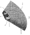
- inventive heat exchanger 10 comprises first and second discs 12 and 14, which substantially build the entire heat exchanger by alternately stacked stacked or strung together and adjacent discs are soldered or glued together, wherein alternately first and second flow channels 16 and 18 are formed.
- the heat exchanger 10 shown can be used as an evaporator of a refrigerant circuit, which is why the flow channels 16 are provided for guiding a refrigerant and the flow channels 18 for guiding air.
- the discs 12 and 14 are formed substantially mirror symmetrical and have an outer shape, which corresponds in the embodiment in about a quarter circle (Fig. 3).
- the discs 12 and 14 At a center 20 of the circle facing the end 20, the discs 12 and 14, two through holes 22 and 24, each through hole 22 and 24 each having a collar 26 and 28, so that in the assembled state of the heat exchanger 10, the collar adjacent discs connected to each other , In particular, are soldered, so that the mutually aligned through holes 22 and 24 each form a plenum for a first medium.
- a feed connection or drain connection not shown, the first medium to the heat exchanger 10 is added or worn.
- the first flow channels 16 are formed by channel-like depressions 30 and 32, respectively, on a first side 34 and 36 of the first and / or second disks 12 and 14 (FIG. 5).
- the channel-like recesses 30 and 32 form the first flow channels 16.
- At least one spring-like web 38 and at least one groove-like groove 40 are provided along the depressions 30 and 32, wherein when joining the first sides 34 and 36, the webs 38 of a disc 12 and 14 in the Grooves 40 of the other disc 14 or 12 fit into each other to lie down and connected to each other, in particular soldered, can (Fig. 5).
- the discs 12 and 14 are thus formed complementary to each other.
- a plurality of the first flow channels 16 are formed by a pair of discs 13, wherein the flow channels 16 are connected in parallel in a pair of discs and are preferably approximately the same length, to which extend the further inwardly extending flow channels 16 at least partially meandering.
- first and / or second disc 12 and 14 On a second side 42 and 44 of the first and / or second disc 12 and 14, webs 46 and 48 projecting from the second side are arranged (FIG. 5). Adjacent discs 12 and 14 are connected to each other via the webs 46 and 48, for example, soldered or glued, wherein the connection along complementary to each other formed end edges 47 and 49 of the webs 46 and 48 takes place. The shape of the end edges is chosen such that when two discs 14 and 12 a montage friendly self-centering takes place.
- the disks 14 and 12 which are connected to one another via their second sides 42 and 44 and the webs 46 and 48 form the second flow channels 18 (FIG. 5).
- the second flow channels 18, which are formed between two disk pairs 13, are connected in parallel and open towards their ends, as can be seen in particular in FIG.
- the second flow channels 18 according to the outer shape of the discs 12 and 14 arcuate, in particular circular arc-shaped, formed (Fig. 4).
- the individual second flow channels 18 are of different lengths and with a greater distance from the inlet for the first medium, ie from the passage opening 22, longer, so that in the vicinity of the inlet, where a relatively large temperature difference between the two media, the flow channels 18 are relatively short, and therefore the heat exchange needs to take place only over a shorter path.
- auxiliary ribs 64 may be disposed in the shorter flow passages 18 near the inlet to enhance heat exchange in the shorter flow passages, as indicated in FIG. 5 in the leftmost flow passage 18.
- the ends of the flow channels 18 are arranged on the one hand on an air inflow side 50 and on the other hand on an air outlet side 52 (FIG. 1).
- the air flowing in the direction 54 enters the flow channels 18 on the air inflow side 50 and undergoes a change in direction as it flows through the heat exchanger 10 and exits the heat exchanger 10 on the air outlet side 52 in the direction 56.
- the air outlet surface 52 is in a diaper ⁇ of about 90 ° to the Lucasanström preparation 50. Other angles are readily conceivable.
- these condensate drainage aids integrated in the panes 12, 14 have recesses 60 in the form of recesses 60 by means of which condensate water settling in the heat exchanger 10 can drain off or drain off (FIG. 6).
- the condensate drainage aids may also have another suitable shape.
- vortex generators 62 can be arranged on the webs 46, 48, which cause a turbulence of the air flowing through the flow channels 18 and thus an improved heat transfer.
- the discs 12 and 14 of the heat exchanger 10 are preferably made of aluminum and are soldered together, which can be done for example in a soldering oven.
- the discs can also be glued together or consist of a non-ferrous metal.
- the heat exchanger 10 is thus constructed in the simplest way from only two different discs 12 and 14. It is also possible to provide at the ends of the heat exchanger 10 flat end plates 62 or just form the outermost discs on one side.
- the heat exchanger 10 according to the invention is preferably used in heating or air conditioning systems, in particular in air conditioning systems, in which CO 2 is used as a refrigerant.
- Fig. 7 an embodiment is shown, in which the heat exchanger 10 is used as the evaporator 102.
- To be conditioned air is supplied from a radial fan 104, not shown directly to the inflow surface 106 of the evaporator 102.
- the air is cooled and simultaneously deflected by about 90 °.
- a mixing flap 112 cold air exiting from the evaporator 102 can be supplied to a heating element 110 and supplied by the heating element 110 to an air mixing chamber 108 as warm air.
- the radiator 110 is formed in the disc construction according to the invention.
- Via bypass flap 144 cold air can be conducted past the heating element 110 and supplied to the air mixing chamber 108.
- the hot air and the cold air are mixed to obtain air of a desired temperature.
- a defrost air passage 118, a foot air passage 122, and an air passage 148 branch to vents in the middle plane of the vehicle.
- the ones from Air mixing chamber 108 branching air ducts are each closed with air dampers.
Landscapes
- Engineering & Computer Science (AREA)
- Physics & Mathematics (AREA)
- Thermal Sciences (AREA)
- Mechanical Engineering (AREA)
- General Engineering & Computer Science (AREA)
- Heat-Exchange Devices With Radiators And Conduit Assemblies (AREA)
- Air-Conditioning For Vehicles (AREA)
Claims (17)
- Echangeur de chaleur du type à plaques comprenant une arrivée pour un premier produit (ou milieu), où au moins un premier canal d'écoulement (16), pour le premier produit, est disposé à chaque fois entre deux plaques (12 et 14) formant une paire de plaques (13), et plusieurs deuxièmes canaux d'écoulement (18) montés en parallèle, pour un deuxième produit (ou milieu), sont disposés à chaque fois entre deux paires de plaques (13), où les deuxièmes canaux d'écoulement (18) montés en parallèle sont formés par des paires de plaques (13) contiguës respectivement à une plaque (14, 12) et présentent un profil de forme arquée, de sorte que le deuxième produit, en traversant l'échangeur de chaleur (10), subit une modification de la direction d'écoulement,
caractérisé en ce que les deuxièmes canaux d'écoulement (18), placés à plus grande distance par rapport à l'arrivée, sont configurés en étant plus longs. - Echangeur de chaleur selon la revendication 1, caractérisé en ce que les deuxièmes canaux d'écoulement (18) s'étendent en forme d'arc de cercle.
- Echangeur de chaleur selon l'une ou l'autre des revendications précédentes, caractérisé en ce qu'une surface d'entrée (50) pour le deuxième produit et une surface de sortie (52) pour le deuxième produit sont disposées l'une par rapport à l'autre, suivant un angle (α).
- Echangeur de chaleur selon l'une quelconque des revendications précédentes, caractérisé en ce que plusieurs premiers canaux d'écoulement (16) montés en parallèle sont formés par une paire de plaques (13), lesquels canaux d'écoulement sont à peu près de la même longueur et au moins certains des premiers canaux d'écoulement (16) s'étendent, au moins par zones, en forme de méandres.
- Echangeur de chaleur selon l'une quelconque des revendications précédentes, caractérisé en ce que les plaques (12, 14) présentent, sur un premier côté (34, 36), des creux (30, 32) en forme de canaux, et des plaques contiguës (12, 14) formant une paire de plaques (13) sont assemblées l'une à l'autre par leurs premiers côtés (34, 36), pour la formation des premiers canaux d'écoulement (16) formés par les creux (30, 32).
- Echangeur de chaleur selon la revendication 5, caractérisé en ce que au moins une partie pleine (38) en forme de languette et au moins une gorge (40) en forme de rainure sont disposées le long des creux (30, 32).
- Echangeur de chaleur selon la revendication 5 ou 6, caractérisé en ce que les plaques (12, 14) présentent des parties pleines (46, 48) dépassant de leur deuxième côté (42, 44), et des plaques contiguës (14, 12) peuvent être assemblées l'une à l'autre par les parties pleines (46, 48), pour la formation des deuxièmes canaux d'écoulement (18).
- Echangeur de chaleur selon l'une quelconque des revendications précédentes, caractérisé en ce que les plaques sont formées par estampage.
- Echangeur de chaleur selon l'une quelconque des revendications précédentes, caractérisé en ce que des plaques (12, 14) respectivement contiguës sont configurées pratiquement de façon symétrique et, dans leurs zones d'assemblage, de façon complémentaire.
- Echangeur de chaleur selon l'une quelconque des revendications précédentes, caractérisé en ce que les plaques (12, 14) présentent des évidements (60) placés au niveau de l'extrémité - éloignée de l'écoulement - des plaques des deuxièmes canaux d'écoulement (18), lesdits évidements servant à l'évacuation de l'eau de condensation.
- Echangeur de chaleur selon l'une quelconque des revendications précédentes, caractérisé en ce que des plaques contiguës sont brasées ou collées l'une à l'autre.
- Echangeur de chaleur selon l'une quelconque des revendications précédentes, caractérisé en ce que les plaques sont en aluminium.
- Echangeur de chaleur selon l'une quelconque des revendications précédentes, caractérisé en ce que la forme extérieure des plaques respectivement contiguës (12, 14) est à peu près celle d'un quart de cercle.
- Système de chauffage ou de climatisation pour un véhicule automobile comprenant au moins un échangeur de chaleur (10) selon l'une quelconque des revendications précédentes 1 à 13.
- Système de chauffage ou de climatisation selon la revendication 14, caractérisé en ce que l'échangeur de chaleur (10) est un évaporateur (102), et du dioxyde de carbone (CO2) servant de produit réfrigérant, ou bien d'autres produits réfrigérants qui fonctionnent à des pressions élevées, traverse les premiers canaux d'écoulement.
- Système de chauffage ou de climatisation selon la revendication 14 ou 15, caractérisé en ce que l'échangeur de chaleur (10) est un évaporateur (102) et/ou un radiateur (110), et de l'air traverse les deuxièmes canaux d'écoulement.
- Système de chauffage ou de climatisation selon l'une des revendications 14, 15 ou 16, caractérisé en ce que l'échangeur de chaleur (10, 102, 110) dévie l'air à peu près de 90°.
Applications Claiming Priority (2)
| Application Number | Priority Date | Filing Date | Title |
|---|---|---|---|
| DE10117400A DE10117400A1 (de) | 2001-04-06 | 2001-04-06 | Wärmeübertrager und diesen enthaltende Heizungs- oder Klimaanlage eines Kraftfahrzeuges |
| DE10117400 | 2001-04-06 |
Publications (2)
| Publication Number | Publication Date |
|---|---|
| EP1247666A1 EP1247666A1 (fr) | 2002-10-09 |
| EP1247666B1 true EP1247666B1 (fr) | 2006-06-21 |
Family
ID=7680773
Family Applications (1)
| Application Number | Title | Priority Date | Filing Date |
|---|---|---|---|
| EP02004904A Expired - Lifetime EP1247666B1 (fr) | 2001-04-06 | 2002-03-05 | Echangeur de chaleur et appareil de chauffage ou climatisation de voiture comprenant un tel échangeur de chaleur |
Country Status (5)
| Country | Link |
|---|---|
| US (1) | US6953081B2 (fr) |
| EP (1) | EP1247666B1 (fr) |
| JP (1) | JP3990172B2 (fr) |
| AT (1) | ATE330803T1 (fr) |
| DE (2) | DE10117400A1 (fr) |
Families Citing this family (13)
| Publication number | Priority date | Publication date | Assignee | Title |
|---|---|---|---|---|
| US6948909B2 (en) * | 2003-09-16 | 2005-09-27 | Modine Manufacturing Company | Formed disk plate heat exchanger |
| DE102004010640A1 (de) * | 2004-03-05 | 2005-09-22 | Modine Manufacturing Co., Racine | Plattenwärmeübertrager |
| TWI267341B (en) * | 2005-04-01 | 2006-11-21 | Foxconn Tech Co Ltd | Heat dissipating device |
| DE102006008218B4 (de) * | 2005-05-26 | 2015-03-26 | Halla Visteon Climate Control Corporation | Kompakte Heizungs-, Lüftungs- und Klimatisierungs-Anlage in Flachbauweise für Kraftfahrzeuge |
| CN100389493C (zh) * | 2005-05-29 | 2008-05-21 | 富准精密工业(深圳)有限公司 | 散热装置 |
| USD570988S1 (en) * | 2008-01-18 | 2008-06-10 | Bou-Matic Technologies Corporation | Heat exchanger |
| DE102008058100A1 (de) * | 2008-11-18 | 2010-05-20 | Behr Gmbh & Co. Kg | Wärmeübertrager zur Beheizung eines Kraftfahrzeugs |
| CA2760514C (fr) * | 2009-05-22 | 2018-03-27 | The Government Of The United States Of America, As Represented By The Secretary Of The Navy | Recuperateur de contre-courant radial compact |
| JP6094095B2 (ja) * | 2012-08-31 | 2017-03-15 | 株式会社デンソー | 車両用空調装置 |
| CA2889399A1 (fr) | 2012-10-31 | 2014-05-08 | Dana Canada Corporation | Echangeur de chaleur a plaques empilees dote d'une conception de plaque unique |
| JP6106503B2 (ja) * | 2013-04-16 | 2017-04-05 | 株式会社ケーヒン・サーマル・テクノロジー | エバポレータおよびこれを用いた車両用空調装置 |
| IL255877B (en) | 2017-11-23 | 2019-12-31 | Dulberg Sharon | A device for extracting water from the air, and for drying the air using high energy and methods for its production |
| JP7567021B2 (ja) * | 2020-07-10 | 2024-10-15 | ハンオン システムズ | 熱交換器 |
Family Cites Families (29)
| Publication number | Priority date | Publication date | Assignee | Title |
|---|---|---|---|---|
| US976203A (en) * | 1909-08-14 | 1910-11-22 | Alfred D Rathbone | Sheet-metal radiator. |
| US1008844A (en) * | 1910-06-30 | 1911-11-14 | Buffalo Radiator Company | Radiator. |
| US1057294A (en) * | 1911-10-16 | 1913-03-25 | Harrison Radiator Company | Radiator. |
| US1619333A (en) * | 1920-11-30 | 1927-03-01 | Westinghouse Electric & Mfg Co | Radiator |
| US1795774A (en) * | 1927-07-21 | 1931-03-10 | Revere Copper & Brass Inc | Radiator for high-pressure systems |
| FR652752A (fr) * | 1927-09-21 | 1929-03-13 | Perfectionnements aux radiateurs à lames d'eau | |
| US1863056A (en) * | 1929-09-03 | 1932-06-14 | Walter E Kuenstler | Radiator |
| US1937713A (en) * | 1930-04-26 | 1933-12-05 | Revere Copper & Brass Inc | Heat transfer apparatus |
| US2097851A (en) * | 1934-04-26 | 1937-11-02 | Wenzl Richard | Air cooler |
| US2036704A (en) * | 1934-08-15 | 1936-04-07 | Walter E Kuenstler | Radiator |
| US2083028A (en) * | 1935-10-14 | 1937-06-08 | Richmond Radiator Company | Radiator |
| FR842632A (fr) * | 1938-08-04 | 1939-06-15 | Perfectionnements apportés aux systèmes de radiateurs pour installations de chauffage central de type domestique ou industriel | |
| US2196318A (en) * | 1938-11-04 | 1940-04-09 | American Radiator & Standard | Radiator |
| GB635713A (en) * | 1946-04-06 | 1950-04-12 | Filiberto Gatta | Radiator |
| DE841337C (de) * | 1950-08-06 | 1952-06-16 | Strebelwerk Ges Mit Beschraenk | Gegossener Glieder-Heizkoerper |
| US2877000A (en) * | 1955-09-16 | 1959-03-10 | Int Harvester Co | Heat exchanger |
| US3104701A (en) * | 1956-01-18 | 1963-09-24 | Olin Mathieson | Heat exchanger |
| DE1455760B2 (de) * | 1965-12-23 | 1976-04-22 | Kühlvorrichtung für ein gepanzertes Fahrzeug Dr.Ing.h.c. F. Porsche AG, 7000 Stuttgart | Kuehlvorrichtung fuer ein gepanzertes fahrzeug |
| NL7513374A (en) * | 1975-11-15 | 1977-05-17 | Giesen Metaalgieterij | Motor vehicle radiator arrangement - has light alloy casting forming central part between two end boxes |
| GB2023796B (en) | 1978-06-19 | 1982-08-25 | Gen Motors Corp | Hollow-plate heat exchange element |
| JP2558019Y2 (ja) * | 1992-09-24 | 1997-12-17 | カルソニック株式会社 | オイルクーラ |
| DE19510847C2 (de) * | 1995-03-17 | 2002-11-21 | Michael Rehberg | Plattenwärmetauscher |
| DE19543149C2 (de) * | 1995-11-18 | 2000-09-14 | Behr Gmbh & Co | Wärmetauscher, insbesondere Kältemittelverdampfer |
| JPH106759A (ja) * | 1996-06-25 | 1998-01-13 | Sanden Corp | 空調装置 |
| JPH1053021A (ja) * | 1996-08-09 | 1998-02-24 | Sanden Corp | 空調装置 |
| JP3677922B2 (ja) * | 1997-02-06 | 2005-08-03 | 株式会社デンソー | 空調装置 |
| DE19719252C2 (de) * | 1997-05-07 | 2002-10-31 | Valeo Klimatech Gmbh & Co Kg | Zweiflutiger und in Luftrichtung einreihiger hartverlöteter Flachrohrverdampfer für eine Kraftfahrzeugklimaanlage |
| DE19832479A1 (de) * | 1998-07-20 | 2000-01-27 | Behr Gmbh & Co | Mit CO¶2¶ betreibbare Klimaanlage |
| DE10010266A1 (de) | 2000-03-02 | 2001-11-15 | Behr Gmbh & Co | Wärmeübertrager und diesen enthaltende Heizungs- oder Klimaanlage eines Kraftfahrzeuges |
-
2001
- 2001-04-06 DE DE10117400A patent/DE10117400A1/de not_active Withdrawn
-
2002
- 2002-03-05 EP EP02004904A patent/EP1247666B1/fr not_active Expired - Lifetime
- 2002-03-05 AT AT02004904T patent/ATE330803T1/de not_active IP Right Cessation
- 2002-03-05 DE DE50207247T patent/DE50207247D1/de not_active Expired - Lifetime
- 2002-03-25 JP JP2002083382A patent/JP3990172B2/ja not_active Expired - Fee Related
- 2002-04-05 US US10/115,891 patent/US6953081B2/en not_active Expired - Fee Related
Also Published As
| Publication number | Publication date |
|---|---|
| JP3990172B2 (ja) | 2007-10-10 |
| US6953081B2 (en) | 2005-10-11 |
| DE10117400A1 (de) | 2002-10-10 |
| EP1247666A1 (fr) | 2002-10-09 |
| JP2002310588A (ja) | 2002-10-23 |
| US20020144810A1 (en) | 2002-10-10 |
| ATE330803T1 (de) | 2006-07-15 |
| DE50207247D1 (de) | 2006-08-03 |
Similar Documents
| Publication | Publication Date | Title |
|---|---|---|
| DE19944951B4 (de) | Klimaanlage mit innerem Wärmeübertrager | |
| DE69611960T2 (de) | Klimaanlage | |
| DE69413300T2 (de) | Gliederwärmetauscher | |
| EP2026028B1 (fr) | Échangeur de chaleur, en particulier pour véhicule automobile | |
| DE60012822T2 (de) | Wärmetauscher | |
| EP1247666B1 (fr) | Echangeur de chaleur et appareil de chauffage ou climatisation de voiture comprenant un tel échangeur de chaleur | |
| DE69911131T2 (de) | Wärmetauscher | |
| DE102006018532A1 (de) | Wärmetauscher | |
| DE10220532A1 (de) | Wärmetauscher | |
| DE19942458B4 (de) | Wärmetauscher für eine Fahrzeug-Klimaanlage | |
| DE112011101771T5 (de) | Wärmetauscher | |
| DE19646349B4 (de) | Verdampfer und damit ausgerüstete Fahrzeugklimaanlage | |
| DE112011101772T5 (de) | Kanal für einen Wärmetauscher, Wärmetauscher und Verfahren zum Herstellen eines Kanals für einen Wärmetauscher | |
| DE10010266A1 (de) | Wärmeübertrager und diesen enthaltende Heizungs- oder Klimaanlage eines Kraftfahrzeuges | |
| EP2798300B1 (fr) | Échangeur thermique | |
| EP3491323B1 (fr) | Échangeur de chaleur présentant une structure à micro-canal ou une structure à tube à ailettes | |
| DE102006002194A1 (de) | Verdampfer, insbesondere für eine Klimaanlage eines Kraftfahrzeuges | |
| DE19804389B4 (de) | Klimaanlage mit Trennwand zur Unterteilung von Luftdurchlässen | |
| EP1536962B1 (fr) | Systeme d'echangeurs thermiques et circuit de chauffe/refroidissement destine a une climatisation d'un vehicule et procede de commande et/ou de reglage d'un circuit de chauffe/refroidissement d'une climatisation | |
| EP2798298B1 (fr) | Transmetteur de chaleur | |
| EP2423016A2 (fr) | Dispositif de mélange de deux flux d'air | |
| EP1816424A1 (fr) | Echangeur thermique pour un cycle frigorifique | |
| EP2049859B1 (fr) | Climatisation pour véhicule à moteur | |
| DE102017009397A1 (de) | Wärmeübertragungsanordnung für einen wärmetauscher | |
| EP0268831A1 (fr) | Lamelle |
Legal Events
| Date | Code | Title | Description |
|---|---|---|---|
| PUAI | Public reference made under article 153(3) epc to a published international application that has entered the european phase |
Free format text: ORIGINAL CODE: 0009012 |
|
| AK | Designated contracting states |
Kind code of ref document: A1 Designated state(s): AT BE CH CY DE DK ES FI FR GB GR IE IT LI LU MC NL PT SE TR |
|
| AX | Request for extension of the european patent |
Free format text: AL;LT;LV;MK;RO;SI |
|
| 17P | Request for examination filed |
Effective date: 20030326 |
|
| AKX | Designation fees paid |
Designated state(s): AT BE CH CY DE DK ES FI FR GB GR IE IT LI LU MC NL PT SE TR |
|
| 17Q | First examination report despatched |
Effective date: 20040113 |
|
| RAP1 | Party data changed (applicant data changed or rights of an application transferred) |
Owner name: BEHR GMBH & CO. KG |
|
| GRAP | Despatch of communication of intention to grant a patent |
Free format text: ORIGINAL CODE: EPIDOSNIGR1 |
|
| GRAS | Grant fee paid |
Free format text: ORIGINAL CODE: EPIDOSNIGR3 |
|
| GRAA | (expected) grant |
Free format text: ORIGINAL CODE: 0009210 |
|
| AK | Designated contracting states |
Kind code of ref document: B1 Designated state(s): AT BE CH CY DE DK ES FI FR GB GR IE IT LI LU MC NL PT SE TR |
|
| PG25 | Lapsed in a contracting state [announced via postgrant information from national office to epo] |
Ref country code: FI Free format text: LAPSE BECAUSE OF FAILURE TO SUBMIT A TRANSLATION OF THE DESCRIPTION OR TO PAY THE FEE WITHIN THE PRESCRIBED TIME-LIMIT Effective date: 20060621 Ref country code: IE Free format text: LAPSE BECAUSE OF FAILURE TO SUBMIT A TRANSLATION OF THE DESCRIPTION OR TO PAY THE FEE WITHIN THE PRESCRIBED TIME-LIMIT Effective date: 20060621 Ref country code: IT Free format text: LAPSE BECAUSE OF FAILURE TO SUBMIT A TRANSLATION OF THE DESCRIPTION OR TO PAY THE FEE WITHIN THE PRESCRIBED TIME-LIMIT;WARNING: LAPSES OF ITALIAN PATENTS WITH EFFECTIVE DATE BEFORE 2007 MAY HAVE OCCURRED AT ANY TIME BEFORE 2007. THE CORRECT EFFECTIVE DATE MAY BE DIFFERENT FROM THE ONE RECORDED. Effective date: 20060621 Ref country code: NL Free format text: LAPSE BECAUSE OF FAILURE TO SUBMIT A TRANSLATION OF THE DESCRIPTION OR TO PAY THE FEE WITHIN THE PRESCRIBED TIME-LIMIT Effective date: 20060621 Ref country code: GB Free format text: LAPSE BECAUSE OF FAILURE TO SUBMIT A TRANSLATION OF THE DESCRIPTION OR TO PAY THE FEE WITHIN THE PRESCRIBED TIME-LIMIT Effective date: 20060621 |
|
| REG | Reference to a national code |
Ref country code: GB Ref legal event code: FG4D Free format text: NOT ENGLISH |
|
| REG | Reference to a national code |
Ref country code: CH Ref legal event code: EP |
|
| REG | Reference to a national code |
Ref country code: IE Ref legal event code: FG4D Free format text: LANGUAGE OF EP DOCUMENT: GERMAN |
|
| REF | Corresponds to: |
Ref document number: 50207247 Country of ref document: DE Date of ref document: 20060803 Kind code of ref document: P |
|
| PG25 | Lapsed in a contracting state [announced via postgrant information from national office to epo] |
Ref country code: DK Free format text: LAPSE BECAUSE OF FAILURE TO SUBMIT A TRANSLATION OF THE DESCRIPTION OR TO PAY THE FEE WITHIN THE PRESCRIBED TIME-LIMIT Effective date: 20060921 Ref country code: SE Free format text: LAPSE BECAUSE OF FAILURE TO SUBMIT A TRANSLATION OF THE DESCRIPTION OR TO PAY THE FEE WITHIN THE PRESCRIBED TIME-LIMIT Effective date: 20060921 |
|
| PG25 | Lapsed in a contracting state [announced via postgrant information from national office to epo] |
Ref country code: ES Free format text: LAPSE BECAUSE OF FAILURE TO SUBMIT A TRANSLATION OF THE DESCRIPTION OR TO PAY THE FEE WITHIN THE PRESCRIBED TIME-LIMIT Effective date: 20061002 |
|
| PG25 | Lapsed in a contracting state [announced via postgrant information from national office to epo] |
Ref country code: PT Free format text: LAPSE BECAUSE OF FAILURE TO SUBMIT A TRANSLATION OF THE DESCRIPTION OR TO PAY THE FEE WITHIN THE PRESCRIBED TIME-LIMIT Effective date: 20061121 |
|
| NLV1 | Nl: lapsed or annulled due to failure to fulfill the requirements of art. 29p and 29m of the patents act | ||
| GBV | Gb: ep patent (uk) treated as always having been void in accordance with gb section 77(7)/1977 [no translation filed] |
Effective date: 20060621 |
|
| ET | Fr: translation filed | ||
| REG | Reference to a national code |
Ref country code: IE Ref legal event code: FD4D |
|
| PLBE | No opposition filed within time limit |
Free format text: ORIGINAL CODE: 0009261 |
|
| STAA | Information on the status of an ep patent application or granted ep patent |
Free format text: STATUS: NO OPPOSITION FILED WITHIN TIME LIMIT |
|
| 26N | No opposition filed |
Effective date: 20070322 |
|
| REG | Reference to a national code |
Ref country code: CH Ref legal event code: PL |
|
| BERE | Be: lapsed |
Owner name: BEHR G.M.B.H. & CO. KG Effective date: 20070331 |
|
| PG25 | Lapsed in a contracting state [announced via postgrant information from national office to epo] |
Ref country code: BE Free format text: LAPSE BECAUSE OF NON-PAYMENT OF DUE FEES Effective date: 20070331 |
|
| PG25 | Lapsed in a contracting state [announced via postgrant information from national office to epo] |
Ref country code: MC Free format text: LAPSE BECAUSE OF NON-PAYMENT OF DUE FEES Effective date: 20070331 |
|
| PG25 | Lapsed in a contracting state [announced via postgrant information from national office to epo] |
Ref country code: CH Free format text: LAPSE BECAUSE OF NON-PAYMENT OF DUE FEES Effective date: 20070331 Ref country code: LI Free format text: LAPSE BECAUSE OF NON-PAYMENT OF DUE FEES Effective date: 20070331 |
|
| PG25 | Lapsed in a contracting state [announced via postgrant information from national office to epo] |
Ref country code: GR Free format text: LAPSE BECAUSE OF FAILURE TO SUBMIT A TRANSLATION OF THE DESCRIPTION OR TO PAY THE FEE WITHIN THE PRESCRIBED TIME-LIMIT Effective date: 20060922 |
|
| PG25 | Lapsed in a contracting state [announced via postgrant information from national office to epo] |
Ref country code: AT Free format text: LAPSE BECAUSE OF NON-PAYMENT OF DUE FEES Effective date: 20070305 |
|
| PGFP | Annual fee paid to national office [announced via postgrant information from national office to epo] |
Ref country code: FR Payment date: 20080319 Year of fee payment: 7 |
|
| PG25 | Lapsed in a contracting state [announced via postgrant information from national office to epo] |
Ref country code: LU Free format text: LAPSE BECAUSE OF NON-PAYMENT OF DUE FEES Effective date: 20070305 Ref country code: CY Free format text: LAPSE BECAUSE OF FAILURE TO SUBMIT A TRANSLATION OF THE DESCRIPTION OR TO PAY THE FEE WITHIN THE PRESCRIBED TIME-LIMIT Effective date: 20060621 |
|
| PG25 | Lapsed in a contracting state [announced via postgrant information from national office to epo] |
Ref country code: TR Free format text: LAPSE BECAUSE OF FAILURE TO SUBMIT A TRANSLATION OF THE DESCRIPTION OR TO PAY THE FEE WITHIN THE PRESCRIBED TIME-LIMIT Effective date: 20060621 |
|
| REG | Reference to a national code |
Ref country code: FR Ref legal event code: ST Effective date: 20091130 |
|
| PG25 | Lapsed in a contracting state [announced via postgrant information from national office to epo] |
Ref country code: FR Free format text: LAPSE BECAUSE OF NON-PAYMENT OF DUE FEES Effective date: 20091123 |
|
| PGFP | Annual fee paid to national office [announced via postgrant information from national office to epo] |
Ref country code: DE Payment date: 20100323 Year of fee payment: 9 |
|
| PG25 | Lapsed in a contracting state [announced via postgrant information from national office to epo] |
Ref country code: DE Free format text: LAPSE BECAUSE OF NON-PAYMENT OF DUE FEES Effective date: 20111001 |
|
| REG | Reference to a national code |
Ref country code: DE Ref legal event code: R119 Ref document number: 50207247 Country of ref document: DE Effective date: 20111001 |