EP1247713B1 - Train de roulement sans jeux de roues pour véhicules ferroviaires - Google Patents
Train de roulement sans jeux de roues pour véhicules ferroviaires Download PDFInfo
- Publication number
- EP1247713B1 EP1247713B1 EP02006809A EP02006809A EP1247713B1 EP 1247713 B1 EP1247713 B1 EP 1247713B1 EP 02006809 A EP02006809 A EP 02006809A EP 02006809 A EP02006809 A EP 02006809A EP 1247713 B1 EP1247713 B1 EP 1247713B1
- Authority
- EP
- European Patent Office
- Prior art keywords
- individual wheels
- motor
- wheels
- synchronous motors
- motors
- Prior art date
- Legal status (The legal status is an assumption and is not a legal conclusion. Google has not performed a legal analysis and makes no representation as to the accuracy of the status listed.)
- Expired - Lifetime
Links
- 230000001360 synchronised effect Effects 0.000 claims abstract description 22
- 230000008878 coupling Effects 0.000 claims abstract description 14
- 238000010168 coupling process Methods 0.000 claims abstract description 14
- 238000005859 coupling reaction Methods 0.000 claims abstract description 14
- 230000005284 excitation Effects 0.000 description 2
- 239000000725 suspension Substances 0.000 description 2
- 230000005540 biological transmission Effects 0.000 description 1
- 238000005096 rolling process Methods 0.000 description 1
Images

Classifications
-
- B—PERFORMING OPERATIONS; TRANSPORTING
- B61—RAILWAYS
- B61F—RAIL VEHICLE SUSPENSIONS, e.g. UNDERFRAMES, BOGIES OR ARRANGEMENTS OF WHEEL AXLES; RAIL VEHICLES FOR USE ON TRACKS OF DIFFERENT WIDTH; PREVENTING DERAILING OF RAIL VEHICLES; WHEEL GUARDS, OBSTRUCTION REMOVERS OR THE LIKE FOR RAIL VEHICLES
- B61F3/00—Types of bogies
- B61F3/16—Types of bogies with a separate axle for each wheel
-
- B—PERFORMING OPERATIONS; TRANSPORTING
- B61—RAILWAYS
- B61C—LOCOMOTIVES; MOTOR RAILCARS
- B61C9/00—Locomotives or motor railcars characterised by the type of transmission system used; Transmission systems specially adapted for locomotives or motor railcars
- B61C9/38—Transmission systems in or for locomotives or motor railcars with electric motor propulsion
- B61C9/52—Transmission systems in or for locomotives or motor railcars with electric motor propulsion with transmission shafts at an angle to the driving axles
-
- B—PERFORMING OPERATIONS; TRANSPORTING
- B61—RAILWAYS
- B61F—RAIL VEHICLE SUSPENSIONS, e.g. UNDERFRAMES, BOGIES OR ARRANGEMENTS OF WHEEL AXLES; RAIL VEHICLES FOR USE ON TRACKS OF DIFFERENT WIDTH; PREVENTING DERAILING OF RAIL VEHICLES; WHEEL GUARDS, OBSTRUCTION REMOVERS OR THE LIKE FOR RAIL VEHICLES
- B61F3/00—Types of bogies
- B61F3/02—Types of bogies with more than one axle
- B61F3/04—Types of bogies with more than one axle with driven axles or wheels
Definitions
- the invention relates to a powered chassis for rail vehicles without wheelsets.
- a single wheel drive for an electric vehicle in which a motor with its stator is attached to a first chassis and in which the first chassis part is supported via a primary suspension in an unsprung second chassis part on which the single wheel is rotatably supported known.
- the rotor of the motor transmits its torque via a coupling device whose radial mobility is greater than the travel of the primary suspension.
- a mechanical coupling lateral pairs of wheels is known from DE 44 46 043 C1, in which a chassis with two parallel side members, which are interconnected by at least one cross member, and two pairs of wheels each consisting of two individual wheels, wherein at least two axially opposed single wheels of one Motor are driven with gear and each single wheel is rotatably mounted in a wheel rail, wherein the wheel rails are arranged parallel to the chassis longitudinal axis at both ends of parallel chassis parts and vertically deflectable about a joint, and the motors with their longitudinal axes parallel to the longitudinal beams, respectively and the wheel rails are formed as a transmission housing.
- Such arrangements have also become known through WO 93/22152.
- the individual wheels or the Einzelradcrue are driven by a respective Asynchronfahrmotor, which are electrically connected in parallel to a common pulse inverter. As a result, they are coupled via an electric slip clutch and not coupled speed-locked.
- the disadvantage here is that the self-stable tracking of the wheelset, i. of the sine wave, is lost, resulting in increased wear on wheels and rails.
- the known solution leads to poor directional stability in rail vehicles without wheelsets.
- the invention has the object to provide a chassis of a rail vehicle, which avoids the above-mentioned disadvantages and enables an economical drive concept of such a chassis.
- a coupling of the two individually driven single wheels or Einzelradcrue is created by an electromagnetic torsion spring by the execution.
- the electromagnetic wheelset also works in case of failure or shutdown of a permanent magnet synchronous motors feeding converter, in particular pulse inverter and in pure rolling of the vehicle by permanent excitation of the synchronous motors.
- a permanent magnet synchronous motors feeding converter in particular pulse inverter
- pure rolling of the vehicle by permanent excitation of the synchronous motors.
- permanent-magnet synchronous motors By using permanent-magnet synchronous motors, the drive efficiency increases, and also electrical noise and pendulum moments of the traction motors are reduced compared to asynchronous motors.
- the synchronous motors drive the single wheels either directly or are mechanically coupled via gears with the single wheels or Einzelradpresen.
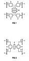
- the 1 shows the basic drive of a chassis with its individual wheels 1.
- the single wheels 1 are driven by coupling means 2 by a synchronous motor 3, preferably a permanent magnet synchronous motor.
- the electrical supply of the synchronous motors 3 of axially adjacent individual wheels 1 takes place in each case via a pulse inverter 4.
- the synchronous motors 3 can be located on the cross members of the chassis or on longitudinal members, not shown.
- two individual wheels 1, which are located behind one another in the direction of travel, are each assigned to a synchronous motor 3, which directly drives these individual wheels via a mechanical coupling device 2.
- FIG 3 shows by way of example a further embodiment of FIG 2 in which the drive of the individual wheels 1 is not directly, but via a gear 5.
- coupling means 2 angular and axial compliant couplings are provided in the described embodiments, e.g. Lugs, curved tooth or wedge pack couplings.
- angular and axial compliant couplings radially and axially compliant couplings, e.g. Parallel crank and Drewirlenkerkuppl12. be used.
- FIG 4 shows an embodiment in which one behind the other single wheels 1 are mechanically rigidly coupled.
- This coupling device 2 can also take place via a gear 5.
- a coupling device 2 the embodiments described in FIG 3 are also suitable.
- the two synchronous motors 3 of a chassis are electrically connected in parallel and are fed by a common pulse inverter.
- the synchronous drives are provided as internal rotor motors or as external rotor motors.
- the electromagnetic wheel set shaft formed according to the invention also functions in the event of failure or disconnection of the pulse inverter and pure coasting of the vehicle due to the permanent excitation of the synchronous motors 3.
- the electromagnetic wheelset shaft furthermore requires no software or commissioning effort. It reduces the wear on wheels and rails, leads to increased ride comfort, and reduced by the electrical parallel connection of the traction motors, in particular permanent-magnet synchronous motors 3, the number of required power inverters.
Landscapes
- Engineering & Computer Science (AREA)
- Mechanical Engineering (AREA)
- Chemical & Material Sciences (AREA)
- Combustion & Propulsion (AREA)
- Transportation (AREA)
- Electric Propulsion And Braking For Vehicles (AREA)
- Platform Screen Doors And Railroad Systems (AREA)
- Train Traffic Observation, Control, And Security (AREA)
Claims (6)
- Train de roulement d'un véhicule sur rails comportant les caractéristiques suivantes :- des roues individuelles (1) qui sont chacune entraînées par des moteurs synchrones (3) excités en permanence,- un couplage électrique des deux roues individuelles (1) opposées par un montage en parallèle et une alimentation des deux moteurs synchrones (3) par l'intermédiaire d'un convertisseur commun, en particulier d'un convertisseur alternatif à impulsions (4).
- Train de roulement selon la revendication 1, caractérisé en ce que les moteurs synchrones (3) entraînent directement les roues individuelles (1).
- Train de roulement selon la revendication 1, caractérisé en ce que les moteurs synchrones (3) entraînent les roues individuelles (1) par l'intermédiaire d'une boîte de vitesses (3).
- Train de roulement muni de roues individuelles (1), dans lequel des roues individuelles (1) sont rigidement couplées par deux l'une derrière l'autre de façon mécanique et sont entraînées par un moteur synchrone (3) commun, les deux moteurs synchrones (3) associés à un train de roulement étant montés électriquement en parallèle et alimentés par un convertisseur commun, en particulier un convertisseur alternatif à impulsions (4).
- Train de roulement selon la revendication 4, caractérisé en ce que les roues individuelles (1) rigidement couplées de façon mécanique sont entraînées par le moteur synchrone (3) par l'intermédiaire d'une boîte de vitesses (5).
- Utilisation d'un train de roulement selon l'une des revendications précédentes, en particulier dans des tramways surbaissés.
Applications Claiming Priority (2)
| Application Number | Priority Date | Filing Date | Title |
|---|---|---|---|
| DE10117031A DE10117031A1 (de) | 2001-04-05 | 2001-04-05 | Triebfahrwerk für Schienenfahrzeuge |
| DE10117031 | 2001-04-05 |
Publications (3)
| Publication Number | Publication Date |
|---|---|
| EP1247713A2 EP1247713A2 (fr) | 2002-10-09 |
| EP1247713A3 EP1247713A3 (fr) | 2003-04-16 |
| EP1247713B1 true EP1247713B1 (fr) | 2006-12-20 |
Family
ID=7680531
Family Applications (1)
| Application Number | Title | Priority Date | Filing Date |
|---|---|---|---|
| EP02006809A Expired - Lifetime EP1247713B1 (fr) | 2001-04-05 | 2002-03-25 | Train de roulement sans jeux de roues pour véhicules ferroviaires |
Country Status (3)
| Country | Link |
|---|---|
| EP (1) | EP1247713B1 (fr) |
| AT (1) | ATE348741T1 (fr) |
| DE (2) | DE10117031A1 (fr) |
Cited By (2)
| Publication number | Priority date | Publication date | Assignee | Title |
|---|---|---|---|---|
| EP2557014A2 (fr) | 2011-08-12 | 2013-02-13 | Traktionssysteme Austria GmbH | Procédé de régulation d'une unité d'entraînement pour véhicules sur rails et unité d'entraînement pour véhicules sur rail |
| US8978563B2 (en) | 2007-04-05 | 2015-03-17 | Alstom Transport Sa | Motor-driven bogie for a streetcar |
Families Citing this family (9)
| Publication number | Priority date | Publication date | Assignee | Title |
|---|---|---|---|---|
| DE10239853A1 (de) * | 2002-08-29 | 2004-03-18 | Siemens Ag | Triebfahrwerk |
| CZ303294B6 (cs) * | 2007-05-29 | 2012-07-18 | ŠKODA TRANSPORTATION a.s. | Hnací podvozek kolejových vozidel s prímým pohonem kol |
| DE102009042870A1 (de) * | 2009-09-24 | 2011-03-31 | Siemens Aktiengesellschaft | Schienenfahrzeug mit Einzelradantrieben |
| DE102013204232B4 (de) * | 2013-03-12 | 2014-11-20 | Siemens Aktiengesellschaft | Asymmetrischer Antrieb eines Schienenfahrzeugs mit Längsradsätzen |
| CN103381837A (zh) * | 2013-06-28 | 2013-11-06 | 长春轨道客车股份有限公司 | 100%低地板独立轮动力转向架双电机同轴两轮同步驱动机构 |
| EP3016833B1 (fr) | 2013-07-05 | 2019-12-25 | Vanderlande Industries B.V. | Véhicule, procédé pour déplacer un tel véhicule et système de transport pour objets comme pièces de bagage |
| CN103723151B (zh) * | 2013-12-30 | 2016-05-11 | 淮北阳光工矿机车制造有限责任公司 | 矿用防爆型永磁同步电动机一级传动电机车 |
| CN103723152A (zh) * | 2013-12-30 | 2014-04-16 | 淮北阳光工矿机车制造有限责任公司 | 一种矿用防爆型永磁电机车一级传动走行装置 |
| DE102017208157A1 (de) * | 2017-05-15 | 2018-11-15 | Siemens Aktiengesellschaft | Verfahren und Vorrichtung zur Überwachung eines Antriebssystems |
Family Cites Families (8)
| Publication number | Priority date | Publication date | Assignee | Title |
|---|---|---|---|---|
| DE3326948A1 (de) * | 1983-07-22 | 1985-01-31 | Licentia Patent-Verwaltungs-Gmbh, 6000 Frankfurt | Verfahren und schaltungsanordnung zum betrieb eines elektrischen triebfahrzeugs mit mehreren an einem umrichter parallel arbeitenden antriebsmotoren |
| JPH0623121Y2 (ja) * | 1986-08-05 | 1994-06-15 | 昌煕 金 | 自動車の電気駆動推進装置 |
| AT400699B (de) * | 1992-04-27 | 1996-02-26 | Elin Energieanwendung | Antriebsanordnung für ein schienenfahrzeug |
| DE4223633A1 (de) * | 1992-07-17 | 1994-01-20 | Siemens Ag | Antriebsmotor |
| DE4446043C1 (de) | 1994-12-22 | 1996-03-07 | Siemens Ag | Fahrwerk für Schienenfahrzeuge |
| DE19714789B4 (de) * | 1997-04-10 | 2010-08-12 | Dwa Deutsche Waggonbau Gmbh | Antriebsgestaltung in Triebfahrzeugen für Niederflurfahrzeuge, insbesondere für Straßenbahnen im innerstädtischen Nahverkehr |
| FR2778612B1 (fr) * | 1998-05-14 | 2000-08-04 | Technicatome | Procede d'alimentation electrique des moteurs des essieux avant et arriere d'un meme vehicule |
| CZ304298A3 (cs) * | 1998-09-22 | 2000-05-17 | Čkd Dopravní Systémy, A. S. | Dvouosý trakční podvozek nízkopodlažního kolejového vozidla s podélně uloženými nezávislými pohonnými jednotkami |
-
2001
- 2001-04-05 DE DE10117031A patent/DE10117031A1/de not_active Withdrawn
-
2002
- 2002-03-25 DE DE50208981T patent/DE50208981D1/de not_active Expired - Lifetime
- 2002-03-25 EP EP02006809A patent/EP1247713B1/fr not_active Expired - Lifetime
- 2002-03-25 AT AT02006809T patent/ATE348741T1/de active
Cited By (2)
| Publication number | Priority date | Publication date | Assignee | Title |
|---|---|---|---|---|
| US8978563B2 (en) | 2007-04-05 | 2015-03-17 | Alstom Transport Sa | Motor-driven bogie for a streetcar |
| EP2557014A2 (fr) | 2011-08-12 | 2013-02-13 | Traktionssysteme Austria GmbH | Procédé de régulation d'une unité d'entraînement pour véhicules sur rails et unité d'entraînement pour véhicules sur rail |
Also Published As
| Publication number | Publication date |
|---|---|
| DE50208981D1 (de) | 2007-02-01 |
| DE10117031A1 (de) | 2002-11-07 |
| EP1247713A3 (fr) | 2003-04-16 |
| ATE348741T1 (de) | 2007-01-15 |
| EP1247713A2 (fr) | 2002-10-09 |
Similar Documents
| Publication | Publication Date | Title |
|---|---|---|
| EP1717090B1 (fr) | Véhicule à toutes roues motrices | |
| EP1247713A2 (fr) | Train de roulement sans jeux de roues pour véhicules ferroviaires | |
| EP0698540A1 (fr) | Train de roulement entraîné pour véhicules ferroviaires | |
| WO2005053134A1 (fr) | Stator d'un mecanisme electrique | |
| EP1685014B2 (fr) | Chassis propulse pour vehicules sur rails, en particulier pour boggies de vehicules a plancher bas | |
| EP1872025B1 (fr) | Accouplement a friction pour au moins une roue porteuse d'un vehicule automoteur sur rails | |
| EP0758602A2 (fr) | Entraînement individuel des essieux de motrices électriques | |
| EP2692607B1 (fr) | Châssis pour véhicule ferroviaire avec liaison fixe amovible entre les roues | |
| EP0542171A1 (fr) | Unité motorisée pour engins de traction ferroviaires | |
| DE102015215576A1 (de) | Traktionsantrieb mit mechanischer Entkopplung | |
| EP0077290B1 (fr) | Transmission en tandem longitudinale pour un véhicule électrique sur rails | |
| EP0760305A2 (fr) | Propulsion de roue indépendante pour véhicule à propulsion électrique | |
| DE19860618C1 (de) | Elektrische Antriebsmaschinenbaueinheit | |
| EP0052244A1 (fr) | Bogie pour véhicules ferroviaires, tel que des tramways | |
| EP3150420A1 (fr) | Groupes d'entrainement pour vehicules | |
| EP2285614A1 (fr) | Dispositif de production et de transmission d'un moment de rotation d'entraînement | |
| EP1393950B1 (fr) | Train de roulement pour véhicules ferroviaires | |
| EP0878368B1 (fr) | Unité d'entraínement pour véhicules ferroviaires | |
| DE2644414A1 (de) | Elektrischer fahrmotor fuer schienengebundene triebfahrzeuge | |
| DE202022100767U1 (de) | Duales Kupplungssystem für den Antrieb von Schienenfahrzeugen | |
| EP3450784B1 (fr) | Accouplement enfichable pour entraînements | |
| DE102019008222A1 (de) | Antriebseinrichtung für einen Kraftwagen, insbesondere für ein Nutzfahrzeug | |
| EP3380380B1 (fr) | Entrainement d'essieu double | |
| DE19922648A1 (de) | Elektrischer Radantrieb für Fahrzeuge | |
| DE390134C (de) | Einrichtung zum elektrischen Antrieb von Fahrzeugen |
Legal Events
| Date | Code | Title | Description |
|---|---|---|---|
| PUAI | Public reference made under article 153(3) epc to a published international application that has entered the european phase |
Free format text: ORIGINAL CODE: 0009012 |
|
| AK | Designated contracting states |
Kind code of ref document: A2 Designated state(s): AT BE CH CY DE DK ES FI FR GB GR IE IT LI LU MC NL PT SE TR |
|
| AX | Request for extension of the european patent |
Free format text: AL;LT;LV;MK;RO;SI |
|
| PUAL | Search report despatched |
Free format text: ORIGINAL CODE: 0009013 |
|
| AK | Designated contracting states |
Designated state(s): AT BE CH CY DE DK ES FI FR GB GR IE IT LI LU MC NL PT SE TR |
|
| AX | Request for extension of the european patent |
Extension state: AL LT LV MK RO SI |
|
| 17P | Request for examination filed |
Effective date: 20030519 |
|
| AKX | Designation fees paid |
Designated state(s): AT DE FR GB |
|
| GRAP | Despatch of communication of intention to grant a patent |
Free format text: ORIGINAL CODE: EPIDOSNIGR1 |
|
| GRAS | Grant fee paid |
Free format text: ORIGINAL CODE: EPIDOSNIGR3 |
|
| GRAA | (expected) grant |
Free format text: ORIGINAL CODE: 0009210 |
|
| AK | Designated contracting states |
Kind code of ref document: B1 Designated state(s): AT DE FR GB |
|
| REG | Reference to a national code |
Ref country code: GB Ref legal event code: FG4D Free format text: NOT ENGLISH |
|
| GBT | Gb: translation of ep patent filed (gb section 77(6)(a)/1977) |
Effective date: 20061220 |
|
| REF | Corresponds to: |
Ref document number: 50208981 Country of ref document: DE Date of ref document: 20070201 Kind code of ref document: P |
|
| ET | Fr: translation filed | ||
| PLBE | No opposition filed within time limit |
Free format text: ORIGINAL CODE: 0009261 |
|
| STAA | Information on the status of an ep patent application or granted ep patent |
Free format text: STATUS: NO OPPOSITION FILED WITHIN TIME LIMIT |
|
| 26N | No opposition filed |
Effective date: 20070921 |
|
| PG25 | Lapsed in a contracting state [announced via postgrant information from national office to epo] |
Ref country code: DE Free format text: LAPSE BECAUSE OF NON-PAYMENT OF DUE FEES Effective date: 20111001 |
|
| PGFP | Annual fee paid to national office [announced via postgrant information from national office to epo] |
Ref country code: FR Payment date: 20120327 Year of fee payment: 11 |
|
| PGFP | Annual fee paid to national office [announced via postgrant information from national office to epo] |
Ref country code: GB Payment date: 20120312 Year of fee payment: 11 |
|
| PGFP | Annual fee paid to national office [announced via postgrant information from national office to epo] |
Ref country code: DE Payment date: 20120518 Year of fee payment: 11 |
|
| PGFP | Annual fee paid to national office [announced via postgrant information from national office to epo] |
Ref country code: AT Payment date: 20120207 Year of fee payment: 11 |
|
| REG | Reference to a national code |
Ref country code: AT Ref legal event code: MM01 Ref document number: 348741 Country of ref document: AT Kind code of ref document: T Effective date: 20130325 |
|
| GBPC | Gb: european patent ceased through non-payment of renewal fee |
Effective date: 20130325 |
|
| REG | Reference to a national code |
Ref country code: FR Ref legal event code: ST Effective date: 20131129 |
|
| REG | Reference to a national code |
Ref country code: DE Ref legal event code: R119 Ref document number: 50208981 Country of ref document: DE Effective date: 20131001 |
|
| PG25 | Lapsed in a contracting state [announced via postgrant information from national office to epo] |
Ref country code: GB Free format text: LAPSE BECAUSE OF NON-PAYMENT OF DUE FEES Effective date: 20130325 Ref country code: AT Free format text: LAPSE BECAUSE OF NON-PAYMENT OF DUE FEES Effective date: 20130325 Ref country code: FR Free format text: LAPSE BECAUSE OF NON-PAYMENT OF DUE FEES Effective date: 20130402 |
|
| PG25 | Lapsed in a contracting state [announced via postgrant information from national office to epo] |
Ref country code: DE Free format text: LAPSE BECAUSE OF NON-PAYMENT OF DUE FEES Effective date: 20131001 |