EP1248032B1 - Installation de pompage et méthode de pompage de fluides - Google Patents
Installation de pompage et méthode de pompage de fluides Download PDFInfo
- Publication number
- EP1248032B1 EP1248032B1 EP02252175A EP02252175A EP1248032B1 EP 1248032 B1 EP1248032 B1 EP 1248032B1 EP 02252175 A EP02252175 A EP 02252175A EP 02252175 A EP02252175 A EP 02252175A EP 1248032 B1 EP1248032 B1 EP 1248032B1
- Authority
- EP
- European Patent Office
- Prior art keywords
- pump
- liquid
- fluid
- vessel
- flow
- Prior art date
- Legal status (The legal status is an assumption and is not a legal conclusion. Google has not performed a legal analysis and makes no representation as to the accuracy of the status listed.)
- Expired - Lifetime
Links
- 239000012530 fluid Substances 0.000 title claims abstract description 71
- 238000000034 method Methods 0.000 title claims description 40
- 238000005086 pumping Methods 0.000 title description 14
- 239000007788 liquid Substances 0.000 claims abstract description 71
- 238000009413 insulation Methods 0.000 claims abstract description 37
- 238000010926 purge Methods 0.000 claims abstract description 19
- 238000011144 upstream manufacturing Methods 0.000 claims abstract description 9
- 239000007789 gas Substances 0.000 claims description 28
- 239000006260 foam Substances 0.000 claims description 11
- IJGRMHOSHXDMSA-UHFFFAOYSA-N Atomic nitrogen Chemical compound N#N IJGRMHOSHXDMSA-UHFFFAOYSA-N 0.000 claims description 8
- 238000001816 cooling Methods 0.000 claims description 7
- XKRFYHLGVUSROY-UHFFFAOYSA-N Argon Chemical compound [Ar] XKRFYHLGVUSROY-UHFFFAOYSA-N 0.000 claims description 6
- CURLTUGMZLYLDI-UHFFFAOYSA-N Carbon dioxide Chemical compound O=C=O CURLTUGMZLYLDI-UHFFFAOYSA-N 0.000 claims description 6
- ATUOYWHBWRKTHZ-UHFFFAOYSA-N Propane Chemical compound CCC ATUOYWHBWRKTHZ-UHFFFAOYSA-N 0.000 claims description 6
- VNWKTOKETHGBQD-UHFFFAOYSA-N methane Chemical compound C VNWKTOKETHGBQD-UHFFFAOYSA-N 0.000 claims description 6
- 239000000203 mixture Substances 0.000 claims description 5
- 229910052757 nitrogen Inorganic materials 0.000 claims description 4
- 238000012546 transfer Methods 0.000 claims description 4
- OTMSDBZUPAUEDD-UHFFFAOYSA-N Ethane Chemical compound CC OTMSDBZUPAUEDD-UHFFFAOYSA-N 0.000 claims description 3
- 229910052786 argon Inorganic materials 0.000 claims description 3
- QVGXLLKOCUKJST-UHFFFAOYSA-N atomic oxygen Chemical compound [O] QVGXLLKOCUKJST-UHFFFAOYSA-N 0.000 claims description 3
- 239000001273 butane Substances 0.000 claims description 3
- 239000001569 carbon dioxide Substances 0.000 claims description 3
- 229910002092 carbon dioxide Inorganic materials 0.000 claims description 3
- 239000001307 helium Substances 0.000 claims description 3
- 229910052734 helium Inorganic materials 0.000 claims description 3
- SWQJXJOGLNCZEY-UHFFFAOYSA-N helium atom Chemical compound [He] SWQJXJOGLNCZEY-UHFFFAOYSA-N 0.000 claims description 3
- 239000001257 hydrogen Substances 0.000 claims description 3
- 229910052739 hydrogen Inorganic materials 0.000 claims description 3
- 125000004435 hydrogen atom Chemical class [H]* 0.000 claims description 3
- IJDNQMDRQITEOD-UHFFFAOYSA-N n-butane Chemical compound CCCC IJDNQMDRQITEOD-UHFFFAOYSA-N 0.000 claims description 3
- OFBQJSOFQDEBGM-UHFFFAOYSA-N n-pentane Natural products CCCCC OFBQJSOFQDEBGM-UHFFFAOYSA-N 0.000 claims description 3
- 239000001301 oxygen Substances 0.000 claims description 3
- 229910052760 oxygen Inorganic materials 0.000 claims description 3
- 239000001294 propane Substances 0.000 claims description 3
- 230000008016 vaporization Effects 0.000 abstract 1
- 239000000047 product Substances 0.000 description 12
- 238000004891 communication Methods 0.000 description 7
- 239000000523 sample Substances 0.000 description 5
- 238000013461 design Methods 0.000 description 4
- 229930195733 hydrocarbon Natural products 0.000 description 3
- 150000002430 hydrocarbons Chemical class 0.000 description 3
- 239000011261 inert gas Substances 0.000 description 3
- 230000007812 deficiency Effects 0.000 description 2
- 238000005057 refrigeration Methods 0.000 description 2
- 230000008439 repair process Effects 0.000 description 2
- 238000013022 venting Methods 0.000 description 2
- 229920005830 Polyurethane Foam Polymers 0.000 description 1
- 238000013459 approach Methods 0.000 description 1
- 230000004888 barrier function Effects 0.000 description 1
- 238000007664 blowing Methods 0.000 description 1
- 230000003028 elevating effect Effects 0.000 description 1
- 238000007710 freezing Methods 0.000 description 1
- 230000008014 freezing Effects 0.000 description 1
- 230000020169 heat generation Effects 0.000 description 1
- 238000010438 heat treatment Methods 0.000 description 1
- 238000012986 modification Methods 0.000 description 1
- 230000004048 modification Effects 0.000 description 1
- 239000012466 permeate Substances 0.000 description 1
- 239000011496 polyurethane foam Substances 0.000 description 1
- 230000003134 recirculating effect Effects 0.000 description 1
- 230000000630 rising effect Effects 0.000 description 1
- 239000000126 substance Substances 0.000 description 1
- 238000005382 thermal cycling Methods 0.000 description 1
- 239000002699 waste material Substances 0.000 description 1
- XLYOFNOQVPJJNP-UHFFFAOYSA-N water Substances O XLYOFNOQVPJJNP-UHFFFAOYSA-N 0.000 description 1
Images

Classifications
-
- F—MECHANICAL ENGINEERING; LIGHTING; HEATING; WEAPONS; BLASTING
- F17—STORING OR DISTRIBUTING GASES OR LIQUIDS
- F17C—VESSELS FOR CONTAINING OR STORING COMPRESSED, LIQUEFIED OR SOLIDIFIED GASES; FIXED-CAPACITY GAS-HOLDERS; FILLING VESSELS WITH, OR DISCHARGING FROM VESSELS, COMPRESSED, LIQUEFIED, OR SOLIDIFIED GASES
- F17C13/00—Details of vessels or of the filling or discharging of vessels
- F17C13/02—Special adaptations of indicating, measuring, or monitoring equipment
- F17C13/026—Special adaptations of indicating, measuring, or monitoring equipment having the temperature as the parameter
-
- F—MECHANICAL ENGINEERING; LIGHTING; HEATING; WEAPONS; BLASTING
- F04—POSITIVE - DISPLACEMENT MACHINES FOR LIQUIDS; PUMPS FOR LIQUIDS OR ELASTIC FLUIDS
- F04B—POSITIVE-DISPLACEMENT MACHINES FOR LIQUIDS; PUMPS
- F04B15/00—Pumps adapted to handle specific fluids, e.g. by selection of specific materials for pumps or pump parts
- F04B15/06—Pumps adapted to handle specific fluids, e.g. by selection of specific materials for pumps or pump parts for liquids near their boiling point, e.g. under subnormal pressure
- F04B15/08—Pumps adapted to handle specific fluids, e.g. by selection of specific materials for pumps or pump parts for liquids near their boiling point, e.g. under subnormal pressure the liquids having low boiling points
-
- F—MECHANICAL ENGINEERING; LIGHTING; HEATING; WEAPONS; BLASTING
- F04—POSITIVE - DISPLACEMENT MACHINES FOR LIQUIDS; PUMPS FOR LIQUIDS OR ELASTIC FLUIDS
- F04D—NON-POSITIVE-DISPLACEMENT PUMPS
- F04D29/00—Details, component parts, or accessories
- F04D29/58—Cooling; Heating; Diminishing heat transfer
- F04D29/586—Cooling; Heating; Diminishing heat transfer specially adapted for liquid pumps
- F04D29/5866—Cooling at last part of the working fluid in a heat exchanger
- F04D29/5873—Cooling at last part of the working fluid in a heat exchanger flow schemes and regulation thereto
-
- F—MECHANICAL ENGINEERING; LIGHTING; HEATING; WEAPONS; BLASTING
- F04—POSITIVE - DISPLACEMENT MACHINES FOR LIQUIDS; PUMPS FOR LIQUIDS OR ELASTIC FLUIDS
- F04D—NON-POSITIVE-DISPLACEMENT PUMPS
- F04D7/00—Pumps adapted for handling specific fluids, e.g. by selection of specific materials for pumps or pump parts
-
- F—MECHANICAL ENGINEERING; LIGHTING; HEATING; WEAPONS; BLASTING
- F17—STORING OR DISTRIBUTING GASES OR LIQUIDS
- F17C—VESSELS FOR CONTAINING OR STORING COMPRESSED, LIQUEFIED OR SOLIDIFIED GASES; FIXED-CAPACITY GAS-HOLDERS; FILLING VESSELS WITH, OR DISCHARGING FROM VESSELS, COMPRESSED, LIQUEFIED, OR SOLIDIFIED GASES
- F17C13/00—Details of vessels or of the filling or discharging of vessels
- F17C13/02—Special adaptations of indicating, measuring, or monitoring equipment
-
- F—MECHANICAL ENGINEERING; LIGHTING; HEATING; WEAPONS; BLASTING
- F17—STORING OR DISTRIBUTING GASES OR LIQUIDS
- F17C—VESSELS FOR CONTAINING OR STORING COMPRESSED, LIQUEFIED OR SOLIDIFIED GASES; FIXED-CAPACITY GAS-HOLDERS; FILLING VESSELS WITH, OR DISCHARGING FROM VESSELS, COMPRESSED, LIQUEFIED, OR SOLIDIFIED GASES
- F17C13/00—Details of vessels or of the filling or discharging of vessels
- F17C13/02—Special adaptations of indicating, measuring, or monitoring equipment
- F17C13/028—Special adaptations of indicating, measuring, or monitoring equipment having the volume as the parameter
-
- F—MECHANICAL ENGINEERING; LIGHTING; HEATING; WEAPONS; BLASTING
- F17—STORING OR DISTRIBUTING GASES OR LIQUIDS
- F17C—VESSELS FOR CONTAINING OR STORING COMPRESSED, LIQUEFIED OR SOLIDIFIED GASES; FIXED-CAPACITY GAS-HOLDERS; FILLING VESSELS WITH, OR DISCHARGING FROM VESSELS, COMPRESSED, LIQUEFIED, OR SOLIDIFIED GASES
- F17C9/00—Methods or apparatus for discharging liquefied or solidified gases from vessels not under pressure
- F17C9/02—Methods or apparatus for discharging liquefied or solidified gases from vessels not under pressure with change of state, e.g. vaporisation
-
- F—MECHANICAL ENGINEERING; LIGHTING; HEATING; WEAPONS; BLASTING
- F17—STORING OR DISTRIBUTING GASES OR LIQUIDS
- F17C—VESSELS FOR CONTAINING OR STORING COMPRESSED, LIQUEFIED OR SOLIDIFIED GASES; FIXED-CAPACITY GAS-HOLDERS; FILLING VESSELS WITH, OR DISCHARGING FROM VESSELS, COMPRESSED, LIQUEFIED, OR SOLIDIFIED GASES
- F17C2205/00—Vessel construction, in particular mounting arrangements, attachments or identifications means
- F17C2205/03—Fluid connections, filters, valves, closure means or other attachments
- F17C2205/0302—Fittings, valves, filters, or components in connection with the gas storage device
- F17C2205/0352—Pipes
- F17C2205/0355—Insulation thereof
-
- F—MECHANICAL ENGINEERING; LIGHTING; HEATING; WEAPONS; BLASTING
- F17—STORING OR DISTRIBUTING GASES OR LIQUIDS
- F17C—VESSELS FOR CONTAINING OR STORING COMPRESSED, LIQUEFIED OR SOLIDIFIED GASES; FIXED-CAPACITY GAS-HOLDERS; FILLING VESSELS WITH, OR DISCHARGING FROM VESSELS, COMPRESSED, LIQUEFIED, OR SOLIDIFIED GASES
- F17C2223/00—Handled fluid before transfer, i.e. state of fluid when stored in the vessel or before transfer from the vessel
- F17C2223/01—Handled fluid before transfer, i.e. state of fluid when stored in the vessel or before transfer from the vessel characterised by the phase
- F17C2223/0146—Two-phase
- F17C2223/0153—Liquefied gas, e.g. LPG, GPL
- F17C2223/0161—Liquefied gas, e.g. LPG, GPL cryogenic, e.g. LNG, GNL, PLNG
-
- F—MECHANICAL ENGINEERING; LIGHTING; HEATING; WEAPONS; BLASTING
- F17—STORING OR DISTRIBUTING GASES OR LIQUIDS
- F17C—VESSELS FOR CONTAINING OR STORING COMPRESSED, LIQUEFIED OR SOLIDIFIED GASES; FIXED-CAPACITY GAS-HOLDERS; FILLING VESSELS WITH, OR DISCHARGING FROM VESSELS, COMPRESSED, LIQUEFIED, OR SOLIDIFIED GASES
- F17C2223/00—Handled fluid before transfer, i.e. state of fluid when stored in the vessel or before transfer from the vessel
- F17C2223/03—Handled fluid before transfer, i.e. state of fluid when stored in the vessel or before transfer from the vessel characterised by the pressure level
- F17C2223/033—Small pressure, e.g. for liquefied gas
-
- F—MECHANICAL ENGINEERING; LIGHTING; HEATING; WEAPONS; BLASTING
- F17—STORING OR DISTRIBUTING GASES OR LIQUIDS
- F17C—VESSELS FOR CONTAINING OR STORING COMPRESSED, LIQUEFIED OR SOLIDIFIED GASES; FIXED-CAPACITY GAS-HOLDERS; FILLING VESSELS WITH, OR DISCHARGING FROM VESSELS, COMPRESSED, LIQUEFIED, OR SOLIDIFIED GASES
- F17C2225/00—Handled fluid after transfer, i.e. state of fluid after transfer from the vessel
- F17C2225/01—Handled fluid after transfer, i.e. state of fluid after transfer from the vessel characterised by the phase
- F17C2225/0146—Two-phase
- F17C2225/0153—Liquefied gas, e.g. LPG, GPL
- F17C2225/0161—Liquefied gas, e.g. LPG, GPL cryogenic, e.g. LNG, GNL, PLNG
-
- F—MECHANICAL ENGINEERING; LIGHTING; HEATING; WEAPONS; BLASTING
- F17—STORING OR DISTRIBUTING GASES OR LIQUIDS
- F17C—VESSELS FOR CONTAINING OR STORING COMPRESSED, LIQUEFIED OR SOLIDIFIED GASES; FIXED-CAPACITY GAS-HOLDERS; FILLING VESSELS WITH, OR DISCHARGING FROM VESSELS, COMPRESSED, LIQUEFIED, OR SOLIDIFIED GASES
- F17C2225/00—Handled fluid after transfer, i.e. state of fluid after transfer from the vessel
- F17C2225/03—Handled fluid after transfer, i.e. state of fluid after transfer from the vessel characterised by the pressure level
- F17C2225/035—High pressure, i.e. between 10 and 80 bars
-
- F—MECHANICAL ENGINEERING; LIGHTING; HEATING; WEAPONS; BLASTING
- F17—STORING OR DISTRIBUTING GASES OR LIQUIDS
- F17C—VESSELS FOR CONTAINING OR STORING COMPRESSED, LIQUEFIED OR SOLIDIFIED GASES; FIXED-CAPACITY GAS-HOLDERS; FILLING VESSELS WITH, OR DISCHARGING FROM VESSELS, COMPRESSED, LIQUEFIED, OR SOLIDIFIED GASES
- F17C2227/00—Transfer of fluids, i.e. method or means for transferring the fluid; Heat exchange with the fluid
- F17C2227/01—Propulsion of the fluid
- F17C2227/0128—Propulsion of the fluid with pumps or compressors
- F17C2227/0135—Pumps
- F17C2227/015—Pumps with cooling of the pump
-
- F—MECHANICAL ENGINEERING; LIGHTING; HEATING; WEAPONS; BLASTING
- F17—STORING OR DISTRIBUTING GASES OR LIQUIDS
- F17C—VESSELS FOR CONTAINING OR STORING COMPRESSED, LIQUEFIED OR SOLIDIFIED GASES; FIXED-CAPACITY GAS-HOLDERS; FILLING VESSELS WITH, OR DISCHARGING FROM VESSELS, COMPRESSED, LIQUEFIED, OR SOLIDIFIED GASES
- F17C2260/00—Purposes of gas storage and gas handling
- F17C2260/03—Dealing with losses
- F17C2260/031—Dealing with losses due to heat transfer
-
- F—MECHANICAL ENGINEERING; LIGHTING; HEATING; WEAPONS; BLASTING
- F17—STORING OR DISTRIBUTING GASES OR LIQUIDS
- F17C—VESSELS FOR CONTAINING OR STORING COMPRESSED, LIQUEFIED OR SOLIDIFIED GASES; FIXED-CAPACITY GAS-HOLDERS; FILLING VESSELS WITH, OR DISCHARGING FROM VESSELS, COMPRESSED, LIQUEFIED, OR SOLIDIFIED GASES
- F17C2270/00—Applications
- F17C2270/05—Applications for industrial use
Definitions
- the present invention generally relates to transferring fluids from a vessel to another location or an end user, and more particularly to pumping cryogenic fluids from a vessel to another location or an end user.
- cryogenic pump systems In general, past attempts to optimize cryogenic pump systems have fallen short of providing an economical and effective means of cooling the pump and minimizing product waste. Most cryogenic pumps in service have no insulation on the inlet line or on the vapor return line. These systems have proven to be wasteful of cryogen, often venting and losing substantial product. To ensure that these systems operate without cavitating, the systems generally have a vacuum jacketed sump at the inlet of the pump that acts as a phase separator. Also, the pump must be cooled down to an appropriate level with a minimum of wasted product.
- One prior art method is to submerge the pump in a supply tank or vessel so that the pump is always cold. Losses for this type of system are primarily due to heat leak of the vessel and heat generation of the pump.
- US-A-4,472,946 (Zwick ) and US-A-4,860,545 (Zwick, et al .) disclose a cryogenic storage tank with a built-in submerged pump that is kept in a continuously cooled down state by the cryogen stored in the tank such that pumping may be commenced immediately.
- This approach attempts to reduce the loss of cryogen through boil-off by minimizing the heat leak path from the environment into the cryogen caused by the presence of the pump inside the tank. This is done by providing an insulated cryogenic storage vessel with a pump mounting tube extending into the vessel and immersed in the cryogen. The outer surface of the pump mounting tube within the vessel is insulated so as to minimize the heat leakage from the pump mounting tube to the cryogen surrounding the tube.
- US-A-5,819,544 discloses a high pressure pumping system for pumping cryogenic liquid from a low pressure holding cylinder to a high pressure gas cylinder (or other high pressure utilization system).
- the system includes a high pressure piston pump having a unidirectional flow input and a unidirectional flow output immersed in the cryogenic liquid in a low pressure pump container that is fed cryogenic liquid from the low pressure holding cylinder.
- the pressure in the pump container is maintained so that driving the pump piston pumps cryogenic liquid from the bulk tank to the high pressure utilization system.
- US-A-5,218,827 discloses a method and apparatus for supplying liquefied gas from a vessel to a pump with subcooling so as to avoid cavitation during pumping. No attempt is made to minimize product losses, only to provide a subcooled liquid to the pump. Problems associated with vent losses are largely ignored.
- US-A-5,537,828 (Borcuch, et al .) discloses a temperature-based cryogenic pump cooldown system wherein the suction or input conduit to the cryogenic pump and the cryogenic pump itself are sequentially cooled prior to pumping. This system also ignores problems associated with vent losses, focusing primarily on how the pump is effectively cooled down and how that cool down is monitored and controlled.
- US-A-5,411,374 discloses a cryogenic fluid pump system and method of pumping cryogenic fluid.
- the system is intended primarily for LNG, although it discusses other cryogenic fluids. It does not discuss insulating the lines, nor does it discuss a conventional vapor return line.
- the pump is required to pump vapor and liquid separately out of the inlet line. Cooldown of the pump is accomplished by recirculating the cryogenic fluid back to the top of the supply tank, which is not an uncommon practice.
- US-A-5,353,849 discloses another method of operating a cryogenic pump, which is complicated by additional methodology used to meter the cryogenic fluid.
- the method used to cool down the pump is similar to that in US-A-5,411,374 (Gram ).
- a liquid sensor e.g., a temperature probe
- US-A-3,630,639 (Durron, et al .) also discloses a method to minimize vent losses in cryogenic pump systems. Specifically, this patent teaches the use of an automatically controlled vent valve in a vent line connected to the suction line in a cryogenic pumping system. The vent valve is in an open position during the cooldown cycle and is moved to a closed position after the system has reached desired operating conditions. Blowby gas which leaks around the piston of the pumping system provides the pressure for closing the vent valve. The vent valve contains an orifice through which the blowby gas bleeds and returns to the storage vessel for the cryogenic fluid being pumped.
- NPSH net positive suction head
- the invention is a method for operating a pumping system to minimize the amount of product lost by the system during operation and cooldown.
- the invention includes various features which, when combined, minimize the loss of product.
- the invention may be used with various types of fluids, it is particularly useful with cryogenic fluids.
- the invention provides a method of cooling a pump for a volatile liquid comprising alternately ceasing the flow of the liquid to the pump to allow at least a portion of liquid remaining in the pump to vaporize to cool the pump, and recommencing flow of the liquid to the pump, the resultant vaporized fluid portion being removed on said recommencement of said flow.
- the flow preferably is controlled by alternating a control means, which controls flow of the liquid to the pump, between an open position, in which the liquid flows through the pump, and a closed position, in which liquid flow through the pump ceases to allow at least a portion of liquid remaining in the pump to vaporize to cool the pump, and removing the resultant vaporized fluid from the pump when the control means returns to the open position.
- the invention provides a method of transferring a volatile liquid from a vessel via a pump comprising the steps:
- the method can be considered as comprising multiple steps.
- the first step is to provide a pump having an inlet and an outlet.
- the second step is to provide a first conduit having a first end and a second end, the first end being in fluid communication with the vessel and the second end being in fluid communication with the inlet of the pump.
- the third step is to provide a first control means in fluid communication with the pump and having an open position and a closed position.
- the first control means is adapted to alternate between the open position and the closed position, whereby a stream of the fluid flows into the inlet of the pump from the first conduit when the first control means first alternates to the open position, the control means alternates to the closed position and at least a part of the stream of the fluid vaporizes in the pump thereby forming a vaporized portion of the fluid, and a stream of the vaporized portion of the fluid flows out of the pump outlet when the first control means alternates again to the open position.
- the fourth step is to alternate the first control means between the open position and the closed position.
- the fifth step is to transmit a first stream of the fluid from the first conduit to the inlet of the pump when the first control means is first in the open position.
- the sixth step is to transmit a first stream of the vaporized portion of the fluid out of the pump outlet when the first control means is again in the open position.
- the fluid of this aspect is a cryogenic fluid.
- the method can be considered as including an additional step of transmitting at least a portion of the stream of vapor to the vessel.
- the method can be considered as including the additional step of sensing a temperature of at least a portion of the fluid in the pump or at least a portion of the fluid upstream or downstream of the pump.
- the method can be considered as including two additional steps.
- the first additional step is to provide a phase separator in fluid communication with the first conduit at a first location between the first end and the second end, the phase separator being adapted to transfer a vapor stream from the first conduit to the vessel.
- the second additional step is to separate a stream of a vapor from at least a portion of the stream of the fluid.
- the method can be considered as including six additional steps.
- the first additional step is to provide a first layer of insulation peripherally surrounding the first conduit.
- the second additional step is to provide a second layer of insulation spaced apart from an peripherally surrounding the first layer of insulation, thereby forming a first space between the first and second layers of insulation.
- the third additional step is to provide a source of a purge gas.
- the fourth additional step is to provide a second conduit having a first end in fluid communication with the source of purge gas and a second end in fluid communication with the first space.
- the fifth step is to provide a second control means for controlling a flow of the purge gas from the source to the first space.
- the sixth step is to transmit a controlled flow of the purge gas from the source of the purge gas to the first space.
- the first layer of insulation can be a closed cell cryogenic foam.
- the source of the purge gas can be in the vessel.
- the purge gas can be selected from nitrogen, helium, argon, oxygen, hydrogen, carbon dioxide, hydrocarbons, and mixtures thereof, the hydrocarbons being selected from methane, ethane, butane, propane and mixtures thereof.
- the method can be considered as including multiple steps.
- the first step is to provide a control means in fluid communication with the pump and having an open position and a closed position.
- the control means is adapted to alternate between the open position and the closed position, whereby a stream of the fluid flows into the inlet of the pump from the source when the control means first alternates to the open position, the first control means alternates to the closed position and at least part of the stream of the fluid vaporizes in the pump thereby forming a vaporized portion of the fluid, and a stream of the vaporized portion of the fluid flows out of the pump outlet when the control means alternates again to the open position.
- the second step is to alternate the control means between the open position and the closed position.
- the third step is to transmit a stream of the fluid from the source of the inlet of the pump when the control means first is in the open position.
- the fourth step is to transmit a stream of the vaporized portion of the fluid out of the pump outlet when the control means is again in the open position.
- the fluid of this aspect is a cryogenic fluid.
- the method can be considered as including a step of alternating the control means between the open and closed positions having five sub-steps.
- the first sub-step is to designate a setpoint for a variable temperature, the temperature to be determined in the pump or at a location upstream or downstream of the pump.
- the second sub-step is to provide a sensing means for sensing the temperature.
- the third sub-step is to move the control means to the open position, thereby allowing a stream of the fluid to flow into the inlet of the pump.
- the fourth sub-step is to move the control means to the closed position when a designated amount of fluid has flowed into the inlet of the pump.
- the fifth sub-step is to move the control means back to the open position when the temperature sensed by the sensing means is less than the set point.
- the method can be considered as including the additional step of sensing a temperature of at least a portion of the fluid in the pump or at least a portion of the fluid upstream or downstream of the pump.
- cryogenic fluids are described herein with regard to cryogenic fluids; but persons skilled in the art will recognize that the invention is not limited to use with cryogenic fluids.
- the invention could be used with relatively cold fluids having temperatures higher than the temperatures of "cryogenic fluids” but which would change phase in the system in a manner similar to that described below for cryogenic fluids.
- a double-acting, two-stage pump that works particularly well with the system and method of this invention is discussed in a patent application being filed concurrently with this application and which is entitled "Double-Acting, Two-Stage Pump” (Air Products and Chemicals, Inc.'s docket number 06112USA).
- Cryogenic temperatures are measured on the absolute or Kelvin scale in which absolute zero is 0 K.
- the cryogenic temperature range is from -150°C (-238°F) to absolute zero (-273°C or -460°F), or 123 K to 0 K.
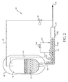
- FIG. 1 One embodiment of the system 10 is illustrated in Figure 1. Alternate embodiments are shown in Figures 2 and 3.
- the cryogenic fluid 12 is stored in a supply tank 14 which is encased in a larger tank 16.
- the fluid is transferred from the supply tank to a pump 20 by an inlet line 18.
- a suction valve 22 in the inlet line may be used to control the flow of fluid from the supply tank to the pump via the inlet line.
- a phase separator 24 in the inlet line separates vapor from the liquid in the fluid.
- the liquid flows to the pump inlet, and the vapor is returned to the supply tank via a vapor return line 32.
- the pump 20 is cooled down by automatically opening and then closing in an alternating manner a pump unloader valve 26 located downstream of the pump outlet.
- the pump unloader valve is in the open position and liquid flows into the pump when the temperature reaches a setpoint, as measured by the temperature probe 38.
- the pump unloader valve moves to the open position and the vapor which boiled off the liquid in the pump is vented to the atmosphere 28.
- the liquid discharged from the pump is transmitted to another location 30 in the system which may be an end user, a tank, etc. (not shown).
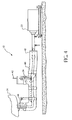
- the inlet line 18 is insulated, and as shown further in Figure 4, the insulation 34 actually comprises multiple layers.
- the first layer of insulation 44 is a closed cell cryogenic foam insulation capable of handling the low temperatures of cryogenic fluids.
- the second layer of insulation 46 preferably is an open cell foam insulation, although a closed cell type of insulation also is acceptable. Because this second layer of insulation typically does not have to handle lower temperature fluids as does the first layer of insulation, an open cell polyurethane foam insulation is preferred for the second layer of insulation.
- an inert gas such as nitrogen, argon or helium, is used for a purge.
- gases could be used for the purge gas, including but not limited to carbon dioxide, oxygen, hydrogen, and certain hydrocarbons (e.g., methane, ethane, butane, propane and mixtures thereof). Although the inert and non-flammable gases are preferred, use of the other gases would be feasible if non-flammable types of insulation are used.
- the purge gas permeates the second layer of insulation 46 (the open cell foam), but remains relatively stagnant around the first layer of insulation 44 (the closed cell foam).
- the outer layer (third layer) of insulation 48 acts as a rain barrier and also is used to contain the purge gas.
- the purge gas is admitted to the space between the first and second layers of insulation via the conduit 42 connected to the supply from which the purge gas is withdrawn. Flow of the purge gas is controlled by the insulation purge flow control valve 36.
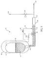
- Figures 2 and 3 show alternate embodiments of the system 10.
- the alternate embodiment shown in Figure 2 is similar to the embodiment in Figure 1, except that the vapor from the pump unloader valve 26 is re-circulated via line 40 to the top of the supply tank 14.
- the second alternate embodiment of the system 10 shown in Figure 3 is similar to the embodiment in Figure 1, except that the pump suction valve 22 is located between the supply tank 14 and the phase separator 24.
- a key feature of the system 10 is the multi-layer design of the insulation 34.
- the insulation is most applicable to situations where a source of dry nitrogen or other inert gas is available that can be used for a purge where this gas otherwise might be vented to atmosphere and thus wasted.
- Cryogenic tanks supplying cryogenic pumping systems typically vent gas due to the heat input to the tank which boils off liquid. That gas can not be consumed by the pump, and is often too great a quantity to simply fill the volume of the removed liquid and so it must be vented.
- this device is a valve connected to a float which allows vapor only (not liquid) that boils off in the inlet line to travel back to the vapor space of the supply tank 14.
- the piping of the vapor return line 32 is greatly simplified. First, there is no need for insulation on the vapor return line. This reduces cost, more than making up for the added cost of the phase separator. Second, the vapor return line does not have to be carefully laid out to ensure that there are no liquid traps in the line.
- a liquid trap in the vapor return line can easily prevent vapor from rising up the vapor return line to the top of the tank, thus creating a bubble that forces liquid out of the inlet line.
- the result is that the pump could have gas at the inlet instead of liquid, resulting in the pump not being able to operate.
- a third key feature of the system 10 is the method of controlling cooldown of the pump 20.
- the system is controlled and monitored to minimize the amount of product used for cooldown of the pump.
- the pump unloader valve 26 opens to atmosphere 28 downstream of the pump allowing liquid to flow into and through the pump.
- the pump unloader valve is then shut to allow this standing liquid to boil off inside the pump, thus cooling down the pump.
- the pump unloader valve is made to operate in an alternating manner as required to ensure that there is liquid inside the pump for cooling.
- the pump unloader valve opens again to vent any vapor inside the pump, and then the valve closes and the pump is allowed to run.
- vapor transmitted from the pump unloader valve can be routed back to the supply tank 14 at the top, the bottom, or another location of the tank. At the same time that the pump unloader valve is opened, the pump can be turned on and the fluid routed back to the supply tank.
- This alternative is shown in Figure 2 for the case where the vapor transmitted from the pump unloader valve is routed (40) back to the top of the tank.
- the pump unloader valve 26 is pulsed, rather than kept open. By doing this, the cryogenic liquid has more time to exchange heat with the pump 20 and the piping, thus using more of the refrigeration capacity of the cryogenic liquid.
Landscapes
- Engineering & Computer Science (AREA)
- Mechanical Engineering (AREA)
- General Engineering & Computer Science (AREA)
- Physics & Mathematics (AREA)
- Thermal Sciences (AREA)
- Filling Or Discharging Of Gas Storage Vessels (AREA)
- Jet Pumps And Other Pumps (AREA)
- Feeding, Discharge, Calcimining, Fusing, And Gas-Generation Devices (AREA)
Claims (14)
- Procédé de refroidissement d'une pompe (20) pour liquide volatil (12) comprenant l'étape consistant à alternativement arrêter la circulation (18) du liquide vers la pompe afin de permettre à une partie du liquide restant dans la pompe de se vaporiser pour refroidir la pompe, et recommencer la circulation du liquide vers la pompe, ladite partie de fluide vaporisée restante étant éliminée (28 ; 40) au moment dudit recommencement de ladite circulation.
- Procédé selon la revendication 1, comprenant les étapes consistant à alterner un moyen de commande (22, 26), qui commande la circulation du liquide vers la pompe (20), entre une position ouverte, dans laquelle le liquide circule à travers la pompe, et une position fermée, dans laquelle la circulation du liquide à travers la pompe cesse, afin de permettre à au moins une partie du liquide restant dans la pompe de se vaporiser pour refroidir la pompe, et éliminer (28; 40) le fluide vaporisé résultant de la pompe lorsque le moyen de commande retourne à la position ouverte.
- Procédé de transfert d'un liquide volatil (12) hors d'un récipient (14) au moyen d'une pompe (20) comprenant les étapes consistant à :(a) tirer un flux de liquide du récipient, en passant par un conduit (18), vers la pompe,(b) arrêter la circulation dudit flux vers la pompe après le transfert d'une partie du liquide hors du récipient à travers la pompe,(c) permettre à au moins une partie du liquide restant dans la pompe de se vaporiser pour refroidir la pompe, et(d) répéter séquentiellement les étapes (a), (b) et (c), la partie de fluide vaporisée produite dans l'étape (c) étant éliminée (28 ; 40) au lancement de l'étape (a).
- Procédé selon la revendication 3 pour le transfert d'un liquide volatil (12) hors d'un récipient (14) au moyen d'une pompe (20) comprenant les étapes consistant à alterner un moyen de commande (22, 26), qui commande la circulation d'un flux de liquide hors d'un récipient, en passant par un conduit (18), vers la pompe, entre une position ouverte, dans laquelle ledit flux circule, par le conduit, vers la pompe, et une position fermée, dans laquelle ladite circulation du liquide par le conduit cesse, afin de permettre à au moins une partie du liquide restant dans la pompe de se vaporiser pour refroidir la pompe, et éliminer (28; 40) le fluide vaporisé résultant de la pompe lorsque le moyen de commande retourne à la position ouverte.
- Procédé selon la revendication 3 ou la revendication 4, dans lequel une partie du liquide (12) se vaporise dans le conduit (18) en amont de la pompe (20) et au moins une partie de ladite partie vaporisée est transférée (32) vers le récipient depuis un séparateur de phases (24) situé à l'amont de la pompe.
- Procédé selon l'une quelconque des revendications 3 à 5, dans lequel un gaz de purge passe par l'espace formé entre une première couche d'isolation (44) entourant de manière périphérique ledit conduit (18) et une seconde couche d'isolation (46) séparée de ladite première couche et entourant de manière périphérique celle-ci.
- Procédé selon la revendication 6 comportant le transfert de partie vaporisée selon la revendication 5, dans lequel le gaz de purge (42) est une autre partie du liquide vaporisé.
- Procédé selon la revendication 6 ou la revendication 7, dans lequel la première couche d'isolation (44) est une mousse à cellules fermées.
- Procédé selon la revendication 8, dans lequel la seconde couche d'isolation (46) est une mousse à cellules ouvertes.
- Procédé selon l'une quelconque des revendications 3 à 7, dans lequel au moins une partie de ladite partie de fluide vaporisée dans la pompe est transférée (40) vers le récipient (14).
- Procédé selon l'une quelconque des revendications précédentes, dans lequel la circulation du liquide cesse après qu'une quantité prédéterminée de fluide a circulé à travers la pompe et reprend en réponse à un capteur de température prédéterminée (38) placée dans la pompe ou en un endroit situé à l'amont ou à l'aval de la pompe.
- Procédé selon l'une quelconque des revendications précédentes, dans lequel le liquide volatil est un liquide cryogénique.
- Procédé selon la revendication 12, dans lequel le liquide cryogénique est sélectionné parmi l'azote liquéfié, l'hélium liquéfié, l'argon liquéfié, l'oxygène liquéfié, l'hydrogène liquéfié, le dioxyde de carbone liquéfié, et leurs mélanges.
- Procédé selon l'une quelconque des revendications 1 à 10, dans lequel le liquide volatil est sélectionné parmi le méthane, l'éthane, le butane, le propane et leurs mélanges.
Priority Applications (1)
| Application Number | Priority Date | Filing Date | Title |
|---|---|---|---|
| EP07107066A EP1808638A3 (fr) | 2001-04-04 | 2002-03-26 | Installation de pompage de fluides |
Applications Claiming Priority (2)
| Application Number | Priority Date | Filing Date | Title |
|---|---|---|---|
| US825784 | 2001-04-04 | ||
| US09/825,784 US6474078B2 (en) | 2001-04-04 | 2001-04-04 | Pumping system and method for pumping fluids |
Related Child Applications (1)
| Application Number | Title | Priority Date | Filing Date |
|---|---|---|---|
| EP07107066A Division EP1808638A3 (fr) | 2001-04-04 | 2002-03-26 | Installation de pompage de fluides |
Publications (3)
| Publication Number | Publication Date |
|---|---|
| EP1248032A2 EP1248032A2 (fr) | 2002-10-09 |
| EP1248032A3 EP1248032A3 (fr) | 2004-05-26 |
| EP1248032B1 true EP1248032B1 (fr) | 2007-06-13 |
Family
ID=25244914
Family Applications (2)
| Application Number | Title | Priority Date | Filing Date |
|---|---|---|---|
| EP02252175A Expired - Lifetime EP1248032B1 (fr) | 2001-04-04 | 2002-03-26 | Installation de pompage et méthode de pompage de fluides |
| EP07107066A Withdrawn EP1808638A3 (fr) | 2001-04-04 | 2002-03-26 | Installation de pompage de fluides |
Family Applications After (1)
| Application Number | Title | Priority Date | Filing Date |
|---|---|---|---|
| EP07107066A Withdrawn EP1808638A3 (fr) | 2001-04-04 | 2002-03-26 | Installation de pompage de fluides |
Country Status (9)
| Country | Link |
|---|---|
| US (1) | US6474078B2 (fr) |
| EP (2) | EP1248032B1 (fr) |
| AT (1) | ATE364816T1 (fr) |
| CA (1) | CA2379643C (fr) |
| DE (1) | DE60220573T2 (fr) |
| DK (1) | DK1248032T3 (fr) |
| ES (1) | ES2286206T3 (fr) |
| MX (1) | MXPA02003337A (fr) |
| PT (1) | PT1248032E (fr) |
Families Citing this family (35)
| Publication number | Priority date | Publication date | Assignee | Title |
|---|---|---|---|---|
| US6775992B2 (en) * | 2001-10-26 | 2004-08-17 | Cooper Research, Llc | Dry air injection system |
| US6912858B2 (en) * | 2003-09-15 | 2005-07-05 | Praxair Technology, Inc. | Method and system for pumping a cryogenic liquid from a storage tank |
| KR100675063B1 (ko) * | 2005-06-27 | 2007-01-29 | 울산화학주식회사 | 저온액화가스의 충전방법 |
| US8083733B2 (en) | 2008-04-16 | 2011-12-27 | Icecure Medical Ltd. | Cryosurgical instrument with enhanced heat exchange |
| FR2931213A1 (fr) * | 2008-05-16 | 2009-11-20 | Air Liquide | Dispositif et procede de pompage d'un fluide cryogenique |
| US7967814B2 (en) | 2009-02-05 | 2011-06-28 | Icecure Medical Ltd. | Cryoprobe with vibrating mechanism |
| WO2010105158A1 (fr) | 2009-03-12 | 2010-09-16 | Icecure Medical Ltd. | Dispositif de cryothérapie et de curiethérapie combinées, et méthode afférente |
| US7967815B1 (en) | 2010-03-25 | 2011-06-28 | Icecure Medical Ltd. | Cryosurgical instrument with enhanced heat transfer |
| US7938822B1 (en) | 2010-05-12 | 2011-05-10 | Icecure Medical Ltd. | Heating and cooling of cryosurgical instrument using a single cryogen |
| US8080005B1 (en) | 2010-06-10 | 2011-12-20 | Icecure Medical Ltd. | Closed loop cryosurgical pressure and flow regulated system |
| JP5780626B2 (ja) * | 2010-09-07 | 2015-09-16 | 学校法人中部大学 | 超伝導送電システム |
| US9494281B2 (en) | 2011-11-17 | 2016-11-15 | Air Products And Chemicals, Inc. | Compressor assemblies and methods to minimize venting of a process gas during startup operations |
| US20140096540A1 (en) * | 2012-10-04 | 2014-04-10 | Stephen Foster | Zero loss cooldown of cryogenic pump |
| WO2016058693A2 (fr) * | 2014-10-16 | 2016-04-21 | Linde Aktiengesellschaft | Réservoir pour stocker un fluide, en particulier sous forme de gas cryogénique |
| JP6635504B2 (ja) * | 2015-12-18 | 2020-01-29 | 川崎重工業株式会社 | 低温液化ガス配管用ガス抜き装置 |
| FR3065941B1 (fr) * | 2017-05-05 | 2025-07-18 | Gaztransport Et Technigaz | Procede de manutention d'une cargaison de gaz liquefie et installation de stockage |
| JP7028156B2 (ja) * | 2018-12-27 | 2022-03-02 | トヨタ自動車株式会社 | 液体水素タンクにおける液面測定方法及び液体水素貯蔵システム |
| CA3133326A1 (fr) * | 2019-03-13 | 2020-09-17 | Icom North America Llc | Systeme d'alimentation en carburant gpl avec prevention de bouchon de vapeur |
| CN111006128A (zh) * | 2019-12-19 | 2020-04-14 | 江苏亚洲气体设备有限公司 | 一种充灌排抽真空装置 |
| US11633224B2 (en) | 2020-02-10 | 2023-04-25 | Icecure Medical Ltd. | Cryogen pump |
| US12523343B2 (en) | 2020-11-10 | 2026-01-13 | Cryoshelter LH2 GmbH | System comprising a cryogenic container and a thermal siphon |
| CN113432032A (zh) * | 2021-05-21 | 2021-09-24 | 长沙中益气体有限公司 | 一种带充装计量的工业气体安全智能供气装置 |
| US12135112B2 (en) | 2021-09-03 | 2024-11-05 | China Energy Investment Corporation Limited | System having cryotank with offset pump housing, method of making and method of using the same |
| US12590676B2 (en) * | 2022-01-07 | 2026-03-31 | Integrated Cryogenic Solutions, LLC | Minimizing recycle flow in pump operation |
| US11686434B1 (en) | 2022-02-22 | 2023-06-27 | China Energy Investment Corporation Limited | Submerged multi-mode cryopump for refueling hydrogen, system having the same, and method of using the same |
| US12426934B2 (en) | 2022-02-28 | 2025-09-30 | Icecure Medical Ltd. | Cryogen flow control |
| US12092093B2 (en) * | 2022-03-08 | 2024-09-17 | Air Products And Chemicals, Inc. | Apparatus and method for cryogenic pump cooldown |
| US11946599B2 (en) | 2022-06-08 | 2024-04-02 | Air Products And Chemicals, Inc. | Apparatus and method for hydrogen fuel dispensing |
| US12215811B2 (en) | 2022-07-18 | 2025-02-04 | Icecure Medical Ltd. | Cryogenic system connector |
| US20240353066A1 (en) | 2023-04-20 | 2024-10-24 | Air Products And Chemicals, Inc. | Apparatus and Method for Dispensing a Cryogenic Fluid |
| US20250075455A1 (en) | 2023-08-30 | 2025-03-06 | Air Products And Chemicals, Inc. | Apparatus and process for fog mitigation |
| US20250075858A1 (en) | 2023-08-30 | 2025-03-06 | Air Products And Chemicals, Inc. | Apparatus and process for cryogenic liquid vaporization to re-cool gas for cryogenic fluid recovery |
| US12527613B2 (en) | 2023-09-11 | 2026-01-20 | Icecure Medical Ltd. | Cryoprobe |
| US20250130554A1 (en) | 2023-10-24 | 2025-04-24 | Air Products And Chemicals, Inc. | Apparatus and process for controlling a display for fuel dispensing |
| US12497936B2 (en) | 2023-11-20 | 2025-12-16 | Air Products And Chemicals, Inc. | Apparatus and process for cooling pressurized gas for fueling |
Family Cites Families (14)
| Publication number | Priority date | Publication date | Assignee | Title |
|---|---|---|---|---|
| US2362724A (en) | 1941-03-08 | 1944-11-14 | Phillips Petroleum Co | Liquefied petroleum gas dispensing system |
| US3630639A (en) | 1969-10-31 | 1971-12-28 | Air Reduction | Suction line vent valve for reciprocating pumps |
| US4277950A (en) * | 1980-02-29 | 1981-07-14 | Union Carbide Corporation | Cryogenic liquid transfer termination apparatus |
| FR2506400B1 (fr) * | 1981-05-19 | 1986-03-21 | Air Liquide | Procede et installation de transfert par pompe d'un liquide cryogenique |
| US4472946A (en) | 1983-01-28 | 1984-09-25 | Zwick Eugene B | Cryogenic storage tank with built-in pump |
| US4881375A (en) * | 1987-10-20 | 1989-11-21 | Air Products And Chemicals, Inc. | Automated cylinder transfill system and method |
| US4860545A (en) | 1988-11-07 | 1989-08-29 | Zwick Energy Research Organization, Inc. | Cryogenic storage tank with a retrofitted in-tank cryogenic pump |
| GB8918218D0 (en) | 1989-08-09 | 1989-09-20 | Boc Group Plc | Thermal insulation |
| US5218827A (en) * | 1992-04-17 | 1993-06-15 | Praxair Technology, Inc. | Pumping of liquified gas |
| US5353849A (en) | 1992-05-27 | 1994-10-11 | Cryogenic Fuels Inc. | Apparatus for metering and transfer of cryogenic liquids |
| US5411374A (en) | 1993-03-30 | 1995-05-02 | Process Systems International, Inc. | Cryogenic fluid pump system and method of pumping cryogenic fluid |
| US5537828A (en) | 1995-07-06 | 1996-07-23 | Praxair Technology, Inc. | Cryogenic pump system |
| US5819544A (en) | 1996-01-11 | 1998-10-13 | Andonian; Martin D. | High pressure cryogenic pumping system |
| US6044647A (en) * | 1997-08-05 | 2000-04-04 | Mve, Inc. | Transfer system for cryogenic liquids |
-
2001
- 2001-04-04 US US09/825,784 patent/US6474078B2/en not_active Expired - Lifetime
-
2002
- 2002-03-26 AT AT02252175T patent/ATE364816T1/de not_active IP Right Cessation
- 2002-03-26 EP EP02252175A patent/EP1248032B1/fr not_active Expired - Lifetime
- 2002-03-26 DK DK02252175T patent/DK1248032T3/da active
- 2002-03-26 DE DE60220573T patent/DE60220573T2/de not_active Expired - Lifetime
- 2002-03-26 PT PT02252175T patent/PT1248032E/pt unknown
- 2002-03-26 EP EP07107066A patent/EP1808638A3/fr not_active Withdrawn
- 2002-03-26 ES ES02252175T patent/ES2286206T3/es not_active Expired - Lifetime
- 2002-03-28 CA CA002379643A patent/CA2379643C/fr not_active Expired - Lifetime
- 2002-04-02 MX MXPA02003337A patent/MXPA02003337A/es active IP Right Grant
Also Published As
| Publication number | Publication date |
|---|---|
| EP1808638A3 (fr) | 2007-10-31 |
| DK1248032T3 (da) | 2007-09-10 |
| US6474078B2 (en) | 2002-11-05 |
| US20020144509A1 (en) | 2002-10-10 |
| EP1248032A2 (fr) | 2002-10-09 |
| ES2286206T3 (es) | 2007-12-01 |
| EP1248032A3 (fr) | 2004-05-26 |
| CA2379643C (fr) | 2006-03-14 |
| MXPA02003337A (es) | 2004-07-16 |
| DE60220573T2 (de) | 2008-02-21 |
| ATE364816T1 (de) | 2007-07-15 |
| CA2379643A1 (fr) | 2002-10-04 |
| EP1808638A2 (fr) | 2007-07-18 |
| DE60220573D1 (de) | 2007-07-26 |
| PT1248032E (pt) | 2007-07-31 |
Similar Documents
| Publication | Publication Date | Title |
|---|---|---|
| EP1248032B1 (fr) | Installation de pompage et méthode de pompage de fluides | |
| CN103090180B (zh) | 液化气体的受控存储 | |
| JP6605703B2 (ja) | 液化ガス貯蔵タンクの断熱障壁に接続されたポンプを制御する方法 | |
| CN110945277B (zh) | 用于将液化气体储存在容器中并将蒸发气体从容器中抽出的方法和设备 | |
| US6505469B1 (en) | Gas dispensing system for cryogenic liquid vessels | |
| US6912858B2 (en) | Method and system for pumping a cryogenic liquid from a storage tank | |
| KR101142901B1 (ko) | 초전도 전력기기용 냉각 시스템 | |
| JP6684789B2 (ja) | 液化ガスを冷却するための装置および方法 | |
| EP2613109B1 (fr) | Procédé de stockage de fluide cryogénique dans un récipient de stockage | |
| WO2004023029A1 (fr) | Station de ravitaillement en gaz liquefie et gaz comprime combinee et procede de fonctionnement correspondant | |
| CA2467338A1 (fr) | Procede et appareil pour chauffer et stocker des fluides froids | |
| CN100422625C (zh) | 深冷液体的贮罐 | |
| US20090071171A1 (en) | Cryogenic liquid storage method and system | |
| KR20010049264A (ko) | 액화 가스를 저장 또는 수송하기 위한 냉각 탱크의 보존방법 및 그 장치 | |
| AU2001238661A1 (en) | System and method for transferring cryogenic fluids | |
| EP4508329A1 (fr) | Pompe cryogénique | |
| CN116677913B (zh) | 氢燃料补给系统及方法 | |
| CN1510329A (zh) | 一种低温液体的气化装置 | |
| RU2827546C1 (ru) | Криогенный сосуд со встроенным экономайзером и способ выпуска сжиженного газа из сосуда | |
| JPH11315998A (ja) | 低温液化ガス貯蔵設備 | |
| JPS6225599Y2 (fr) |
Legal Events
| Date | Code | Title | Description |
|---|---|---|---|
| PUAI | Public reference made under article 153(3) epc to a published international application that has entered the european phase |
Free format text: ORIGINAL CODE: 0009012 |
|
| AK | Designated contracting states |
Kind code of ref document: A2 Designated state(s): AT BE CH CY DE DK ES FI FR GB GR IE IT LI LU MC NL PT SE TR |
|
| AX | Request for extension of the european patent |
Free format text: AL;LT;LV;MK;RO;SI |
|
| PUAL | Search report despatched |
Free format text: ORIGINAL CODE: 0009013 |
|
| AK | Designated contracting states |
Kind code of ref document: A3 Designated state(s): AT BE CH CY DE DK ES FI FR GB GR IE IT LI LU MC NL PT SE TR |
|
| AX | Request for extension of the european patent |
Extension state: AL LT LV MK RO SI |
|
| 17P | Request for examination filed |
Effective date: 20040707 |
|
| AKX | Designation fees paid |
Designated state(s): AT BE CH CY DE DK ES FI FR GB GR IE IT LI LU MC NL PT SE TR |
|
| 17Q | First examination report despatched |
Effective date: 20050428 |
|
| GRAP | Despatch of communication of intention to grant a patent |
Free format text: ORIGINAL CODE: EPIDOSNIGR1 |
|
| GRAS | Grant fee paid |
Free format text: ORIGINAL CODE: EPIDOSNIGR3 |
|
| GRAA | (expected) grant |
Free format text: ORIGINAL CODE: 0009210 |
|
| AK | Designated contracting states |
Kind code of ref document: B1 Designated state(s): AT BE CH CY DE DK ES FI FR GB GR IE IT LI LU MC NL PT SE TR |
|
| PG25 | Lapsed in a contracting state [announced via postgrant information from national office to epo] |
Ref country code: LI Free format text: LAPSE BECAUSE OF FAILURE TO SUBMIT A TRANSLATION OF THE DESCRIPTION OR TO PAY THE FEE WITHIN THE PRESCRIBED TIME-LIMIT Effective date: 20070613 Ref country code: CH Free format text: LAPSE BECAUSE OF FAILURE TO SUBMIT A TRANSLATION OF THE DESCRIPTION OR TO PAY THE FEE WITHIN THE PRESCRIBED TIME-LIMIT Effective date: 20070613 |
|
| REG | Reference to a national code |
Ref country code: GB Ref legal event code: FG4D |
|
| REG | Reference to a national code |
Ref country code: CH Ref legal event code: EP |
|
| REG | Reference to a national code |
Ref country code: IE Ref legal event code: FG4D |
|
| REF | Corresponds to: |
Ref document number: 60220573 Country of ref document: DE Date of ref document: 20070726 Kind code of ref document: P |
|
| REG | Reference to a national code |
Ref country code: PT Ref legal event code: SC4A Free format text: AVAILABILITY OF NATIONAL TRANSLATION Effective date: 20070719 |
|
| REG | Reference to a national code |
Ref country code: DK Ref legal event code: T3 |
|
| REG | Reference to a national code |
Ref country code: SE Ref legal event code: TRGR |
|
| ET | Fr: translation filed | ||
| PG25 | Lapsed in a contracting state [announced via postgrant information from national office to epo] |
Ref country code: AT Free format text: LAPSE BECAUSE OF FAILURE TO SUBMIT A TRANSLATION OF THE DESCRIPTION OR TO PAY THE FEE WITHIN THE PRESCRIBED TIME-LIMIT Effective date: 20070613 |
|
| REG | Reference to a national code |
Ref country code: ES Ref legal event code: FG2A Ref document number: 2286206 Country of ref document: ES Kind code of ref document: T3 |
|
| REG | Reference to a national code |
Ref country code: CH Ref legal event code: PL |
|
| PLBE | No opposition filed within time limit |
Free format text: ORIGINAL CODE: 0009261 |
|
| STAA | Information on the status of an ep patent application or granted ep patent |
Free format text: STATUS: NO OPPOSITION FILED WITHIN TIME LIMIT |
|
| PG25 | Lapsed in a contracting state [announced via postgrant information from national office to epo] |
Ref country code: GR Free format text: LAPSE BECAUSE OF FAILURE TO SUBMIT A TRANSLATION OF THE DESCRIPTION OR TO PAY THE FEE WITHIN THE PRESCRIBED TIME-LIMIT Effective date: 20070914 |
|
| PGFP | Annual fee paid to national office [announced via postgrant information from national office to epo] |
Ref country code: DK Payment date: 20080212 Year of fee payment: 7 |
|
| 26N | No opposition filed |
Effective date: 20080314 |
|
| PGFP | Annual fee paid to national office [announced via postgrant information from national office to epo] |
Ref country code: FI Payment date: 20080229 Year of fee payment: 7 Ref country code: IE Payment date: 20080123 Year of fee payment: 7 Ref country code: PT Payment date: 20080103 Year of fee payment: 7 Ref country code: SE Payment date: 20080310 Year of fee payment: 7 |
|
| PG25 | Lapsed in a contracting state [announced via postgrant information from national office to epo] |
Ref country code: MC Free format text: LAPSE BECAUSE OF NON-PAYMENT OF DUE FEES Effective date: 20080331 |
|
| PG25 | Lapsed in a contracting state [announced via postgrant information from national office to epo] |
Ref country code: CY Free format text: LAPSE BECAUSE OF FAILURE TO SUBMIT A TRANSLATION OF THE DESCRIPTION OR TO PAY THE FEE WITHIN THE PRESCRIBED TIME-LIMIT Effective date: 20070613 |
|
| REG | Reference to a national code |
Ref country code: PT Ref legal event code: MM4A Free format text: LAPSE DUE TO NON-PAYMENT OF FEES Effective date: 20090928 |
|
| PG25 | Lapsed in a contracting state [announced via postgrant information from national office to epo] |
Ref country code: FI Free format text: LAPSE BECAUSE OF NON-PAYMENT OF DUE FEES Effective date: 20090326 Ref country code: PT Free format text: LAPSE BECAUSE OF NON-PAYMENT OF DUE FEES Effective date: 20090928 |
|
| REG | Reference to a national code |
Ref country code: DK Ref legal event code: EBP |
|
| EUG | Se: european patent has lapsed | ||
| PG25 | Lapsed in a contracting state [announced via postgrant information from national office to epo] |
Ref country code: IE Free format text: LAPSE BECAUSE OF NON-PAYMENT OF DUE FEES Effective date: 20090326 |
|
| PG25 | Lapsed in a contracting state [announced via postgrant information from national office to epo] |
Ref country code: DK Free format text: LAPSE BECAUSE OF NON-PAYMENT OF DUE FEES Effective date: 20090331 |
|
| PG25 | Lapsed in a contracting state [announced via postgrant information from national office to epo] |
Ref country code: LU Free format text: LAPSE BECAUSE OF NON-PAYMENT OF DUE FEES Effective date: 20080326 |
|
| PG25 | Lapsed in a contracting state [announced via postgrant information from national office to epo] |
Ref country code: TR Free format text: LAPSE BECAUSE OF FAILURE TO SUBMIT A TRANSLATION OF THE DESCRIPTION OR TO PAY THE FEE WITHIN THE PRESCRIBED TIME-LIMIT Effective date: 20070613 |
|
| PG25 | Lapsed in a contracting state [announced via postgrant information from national office to epo] |
Ref country code: SE Free format text: LAPSE BECAUSE OF NON-PAYMENT OF DUE FEES Effective date: 20090327 |
|
| PGFP | Annual fee paid to national office [announced via postgrant information from national office to epo] |
Ref country code: IT Payment date: 20120323 Year of fee payment: 11 |
|
| PG25 | Lapsed in a contracting state [announced via postgrant information from national office to epo] |
Ref country code: IT Free format text: LAPSE BECAUSE OF NON-PAYMENT OF DUE FEES Effective date: 20140326 |
|
| REG | Reference to a national code |
Ref country code: FR Ref legal event code: PLFP Year of fee payment: 15 |
|
| REG | Reference to a national code |
Ref country code: FR Ref legal event code: PLFP Year of fee payment: 16 |
|
| REG | Reference to a national code |
Ref country code: FR Ref legal event code: PLFP Year of fee payment: 17 |
|
| PGFP | Annual fee paid to national office [announced via postgrant information from national office to epo] |
Ref country code: FR Payment date: 20210210 Year of fee payment: 20 Ref country code: NL Payment date: 20210312 Year of fee payment: 20 |
|
| PGFP | Annual fee paid to national office [announced via postgrant information from national office to epo] |
Ref country code: GB Payment date: 20210317 Year of fee payment: 20 Ref country code: BE Payment date: 20210217 Year of fee payment: 20 Ref country code: DE Payment date: 20210316 Year of fee payment: 20 |
|
| PGFP | Annual fee paid to national office [announced via postgrant information from national office to epo] |
Ref country code: ES Payment date: 20210405 Year of fee payment: 20 |
|
| REG | Reference to a national code |
Ref country code: DE Ref legal event code: R071 Ref document number: 60220573 Country of ref document: DE |
|
| REG | Reference to a national code |
Ref country code: NL Ref legal event code: MK Effective date: 20220325 |
|
| REG | Reference to a national code |
Ref country code: BE Ref legal event code: MK Effective date: 20220326 |
|
| REG | Reference to a national code |
Ref country code: GB Ref legal event code: PE20 Expiry date: 20220325 |
|
| PG25 | Lapsed in a contracting state [announced via postgrant information from national office to epo] |
Ref country code: GB Free format text: LAPSE BECAUSE OF EXPIRATION OF PROTECTION Effective date: 20220325 |
|
| REG | Reference to a national code |
Ref country code: ES Ref legal event code: FD2A Effective date: 20220629 |
|
| PG25 | Lapsed in a contracting state [announced via postgrant information from national office to epo] |
Ref country code: ES Free format text: LAPSE BECAUSE OF EXPIRATION OF PROTECTION Effective date: 20220327 |