EP1248036A2 - Anordnung zum schnellen Befestigen einer Leuchte, insbesondere einer Pendelleuchte - Google Patents
Anordnung zum schnellen Befestigen einer Leuchte, insbesondere einer Pendelleuchte Download PDFInfo
- Publication number
- EP1248036A2 EP1248036A2 EP02007639A EP02007639A EP1248036A2 EP 1248036 A2 EP1248036 A2 EP 1248036A2 EP 02007639 A EP02007639 A EP 02007639A EP 02007639 A EP02007639 A EP 02007639A EP 1248036 A2 EP1248036 A2 EP 1248036A2
- Authority
- EP
- European Patent Office
- Prior art keywords
- assembly
- supporting
- retaining assembly
- lighting fixture
- retaining
- Prior art date
- Legal status (The legal status is an assumption and is not a legal conclusion. Google has not performed a legal analysis and makes no representation as to the accuracy of the status listed.)
- Withdrawn
Links
- 230000008878 coupling Effects 0.000 claims abstract description 11
- 238000010168 coupling process Methods 0.000 claims abstract description 11
- 238000005859 coupling reaction Methods 0.000 claims abstract description 11
- 230000013011 mating Effects 0.000 claims description 14
- 238000006073 displacement reaction Methods 0.000 claims 1
- 239000002184 metal Substances 0.000 description 3
- 230000002093 peripheral effect Effects 0.000 description 3
- 230000004075 alteration Effects 0.000 description 2
- 230000006378 damage Effects 0.000 description 2
- 208000027418 Wounds and injury Diseases 0.000 description 1
- 208000014674 injury Diseases 0.000 description 1
- 230000037431 insertion Effects 0.000 description 1
- 238000003780 insertion Methods 0.000 description 1
- 230000000284 resting effect Effects 0.000 description 1
Images

Classifications
-
- F—MECHANICAL ENGINEERING; LIGHTING; HEATING; WEAPONS; BLASTING
- F21—LIGHTING
- F21V—FUNCTIONAL FEATURES OR DETAILS OF LIGHTING DEVICES OR SYSTEMS THEREOF; STRUCTURAL COMBINATIONS OF LIGHTING DEVICES WITH OTHER ARTICLES, NOT OTHERWISE PROVIDED FOR
- F21V21/00—Supporting, suspending, or attaching arrangements for lighting devices; Hand grips
- F21V21/02—Wall, ceiling, or floor bases; Fixing pendants or arms to the bases
-
- F—MECHANICAL ENGINEERING; LIGHTING; HEATING; WEAPONS; BLASTING
- F16—ENGINEERING ELEMENTS AND UNITS; GENERAL MEASURES FOR PRODUCING AND MAINTAINING EFFECTIVE FUNCTIONING OF MACHINES OR INSTALLATIONS; THERMAL INSULATION IN GENERAL
- F16B—DEVICES FOR FASTENING OR SECURING CONSTRUCTIONAL ELEMENTS OR MACHINE PARTS TOGETHER, e.g. NAILS, BOLTS, CIRCLIPS, CLAMPS, CLIPS OR WEDGES; JOINTS OR JOINTING
- F16B9/00—Connections of rods or tubular parts to flat surfaces at an angle
- F16B9/05—Connections of rods or tubular parts to flat surfaces at an angle by way of an intermediate member
- F16B9/052—Connections of rods or tubular parts to flat surfaces at an angle by way of an intermediate member the intermediate member having a radial flange secured to the flat surface
-
- F—MECHANICAL ENGINEERING; LIGHTING; HEATING; WEAPONS; BLASTING
- F16—ENGINEERING ELEMENTS AND UNITS; GENERAL MEASURES FOR PRODUCING AND MAINTAINING EFFECTIVE FUNCTIONING OF MACHINES OR INSTALLATIONS; THERMAL INSULATION IN GENERAL
- F16B—DEVICES FOR FASTENING OR SECURING CONSTRUCTIONAL ELEMENTS OR MACHINE PARTS TOGETHER, e.g. NAILS, BOLTS, CIRCLIPS, CLAMPS, CLIPS OR WEDGES; JOINTS OR JOINTING
- F16B21/00—Means for preventing relative axial movement of a pin, spigot, shaft or the like and a member surrounding it; Stud-and-socket releasable fastenings
- F16B21/02—Releasable fastening devices locking by rotation
-
- F16B9/026—
-
- F—MECHANICAL ENGINEERING; LIGHTING; HEATING; WEAPONS; BLASTING
- F21—LIGHTING
- F21V—FUNCTIONAL FEATURES OR DETAILS OF LIGHTING DEVICES OR SYSTEMS THEREOF; STRUCTURAL COMBINATIONS OF LIGHTING DEVICES WITH OTHER ARTICLES, NOT OTHERWISE PROVIDED FOR
- F21V21/00—Supporting, suspending, or attaching arrangements for lighting devices; Hand grips
- F21V21/10—Pendants, arms, or standards; Fixing lighting devices to pendants, arms, or standards
- F21V21/104—Pendants
Definitions
- the present invention relates to a fast-fit fastening device for a lighting fixture, in particular a suspended lighting fixture.
- a fast-fit fastening device for a lighting fixture, in particular a suspended lighting fixture, the device comprising a supporting assembly fittable integrally to a supporting wall, and a retaining assembly carried by the lighting fixture and connectable to the supporting assembly; the device being characterized by comprising coupling means for axially connecting said retaining assembly to said supporting assembly with a predetermined axial slack; and tightening means for reducing said axial slack between the retaining assembly and the supporting assembly, and connecting said retaining assembly integrally to said supporting assembly.
- the device according to the invention is thus cheap and easy to produce; is adaptable, with no major alterations, to different types of lighting fixtures; and provides for fastening fixtures quickly, easily and safely.
- number 1 indicates as a whole a fast-fit device for fastening a lighting fixture 2 to a supporting wall 3.
- lighting fixture 2 is a suspended, i.e. ceiling, type, and comprises a body 4 of any form and housing at least one light source (not shown).
- Supporting wall 3 may be a portion of a ceiling or false ceiling, or a decorative element such as a ceiling-rose, box, etc. in turn fixed integrally to the ceiling in any known manner.
- Device 1 comprises a supporting assembly 5 fittable integrally to supporting wall 3; and a retaining assembly 6 carried by lighting fixture 2 and connectable to supporting assembly 5 by coupling means 7 for connecting retaining assembly 6 axially to supporting assembly 5 with a predetermined axial slack, and by tightening means 8 for reducing the axial slack between retaining assembly 6 and supporting assembly 5, and connecting retaining assembly 6 integrally to supporting assembly 5 as explained later on.
- Coupling means 7 provide for connecting retaining assembly 6 to supporting assembly 5 in rotary and axially slack manner by moving retaining assembly 6 axially along an axis A and then rotating it, and comprise a seat 10, formed in supporting assembly 5 and through which retaining assembly 6 is inserted axially, and a connecting head 11 carried by retaining assembly 6.
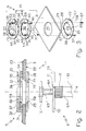
- supporting assembly 5 comprises a front member 20 and a rear member 21, which fit on to respective opposite faces 22, 23 of supporting wall 3; and fastening means for fastening members 20, 21 to each other, with supporting wall 3 in between.
- member 20 is defined by a substantially circular metal plate having an axially through opening 25 of substantially the same shape as connecting head 11, which in fact is insertable loosely through opening 25.
- Opening 25 comprises a substantially circular central portion 26, from which diametrically opposite lateral portions 27 extend; and a peripheral edge 28 of member 20 comprises two diametrically opposite connecting portions 29 perpendicular to lateral portions 27 of opening 25.
- Member 21 is defined by two superimposed substantially circular metal plates 31, 32, which are connected integrally to each other, e.g. by means of screws 33 recessed in respective pairs of holes 34, 35 formed in plates 31, 32, and have respective axially through openings 36, 37 aligned with each other.
- Opening 36 in plate 31 is substantially cross-shaped, and comprises two perpendicular arms 41, 42, both substantially the same shape as opening 25 in member 20 and defined by four radially inner portions 44 arranged symmetrically 90° apart.
- a peripheral edge 45 of plate 31 has a radial slit 46 communicating with opening 36, and in particular with arm 42.
- Opening 37 in plate 32 is a substantially circular opening defined by a radially inner edge 53; two diametrically opposite radial portions 54 extend radially inwards from edge 53; and a peripheral edge 55 of plate 32 has a radial slit 56 communicating with opening 37.
- Plates 31, 32 are connected face to face to each other to define member 21, so that openings 36, 37 and respective slits 46, 56 are superimposed and aligned, and radial portions 54 on plate 32 are superimposed on a pair of diametrically opposite radial portions 44 on plate 31.
- the fastening means for fastening members 20, 21 together comprise two screws 57 recessed inside respective holes 58 formed through member 20, and inside respective pairs of holes 59, 60 formed through radial portions 44, 54 of plates 31, 32.
- retaining assembly 6 comprises a connecting member 61in the example shown, defined by a hollow tubular member projecting from body 4 of lighting fixture 2.
- Connecting member 61 has one end 62 fixed integrally in any known manner to body 4; and one end 63 opposite end 62 and from which projects axially a hollow, externally threaded rod 64.
- Connecting head 11 projects crosswise from a free end 65 of rod 64, and comprises a central portion 66 connected integrally to the free end 65 of rod 64, and two catches 67 symmetrical and diametrically opposite with respect to central portion 66.
- a cable 68 is housed through connecting member 68 and rod 64, is connected to the light source of lighting fixture 2, and is fitted with a connector 69.
- Tightening means 8 comprise an internally threaded ring nut 70, which is fitted in rotary and axially sliding manner to connecting member 61, is connected to rod 64 to form a screw-nut screw coupling, and has an annular end edge 71 facing the free end 65 of rod 64 to rest axially on a flange 72 fitted to slide freely on rod 64 and defined, in the example shown, by a metal plate of any shape.
- Flange 72 defines a mating portion 73 of retaining assembly 6, which in use cooperates with a mating surface 74 of member 20 (mating surface 74 being defined, in the example shown, by the face of member 20 opposite the face mating with supporting wall 3).
- flange 72 is dispensed with, in which case, mating portion 73 is defined by annular end edge 71 of ring nut 70.
- supporting assembly 5 is first fitted directly on to supporting wall 3, in which a substantially circular through opening 75 (Figure 3), of such a diameter as to permit through insertion of connecting head 11, has been formed beforehand.
- a cable 76 ( Figure 1) hangs through opening 75, and is fitted with a connector 77 to connect lighting fixture 2 to the electric system.
- Member 20 and the preassembled member 21 are placed respectively on opposite faces 22, 23 of supporting wall 3, at opening 75 ( Figure 2).
- Member 21 can be inserted easily through opening 75 by virtue of slits 46, 56 (which are wider than the thickness of wall 3).
- Members 20, 21 are then aligned with each other, so that opening 25 is aligned with arm 41, and holes 58 are aligned with holes 59, 60; and members 20, 21 are then fastened to each other, with supporting wall 3 in between, by means of screws 57 inserted through holes 58, 59, 60, so that supporting wall 3 is gripped between members 20 and 21.
- connectors 69, 77 and respective cables 68, 76 are inserted through opening 75 and concealed by supporting wall 3.
- Retaining assembly 6 (supporting lighting fixture 2) is then connected to supporting assembly 5 as follows: gripping connecting member 61, the fitter inserts retaining assembly 6, axially along axis A in Figure 2, inside seat 10, with connecting head 11 aligned with opening 25 and, therefore, with arm 41 of opening 36; and connecting head 11 is inserted axially inside seat 10 until mating portion 73 (i.e. flange 72 resting on end edge 71 of ring nut 70) comes to rest against mating surface 74 of member 20.
- mating portion 73 i.e. flange 72 resting on end edge 71 of ring nut 70
- connecting head 11 is located inside seat 10, substantially on a level with plate 32, so as to interfere radially with radial portions 54 of plate 32, but not with radial portions 44 of plate 31. More specifically, catches 67 on connecting head 11 rest circumferentially against respective first sides 78 of radial portions 54.
- Retaining assembly 6 is then rotated 90° (anticlockwise, in the example shown) so that connecting head 11, which slides over radial portions 44, is aligned with arm 42 of opening 36, and catches 67 come to rest against respective second sides 79 of radial portions 54, which therefore act as stop means for arresting and determining a given rotation (90° in the example shown) of retaining assembly 6 with respect to supporting assembly 5.
- Catches 67 of connecting head 11 are therefore located over connecting portions 29, so that, if lighting fixture 2 is released (intentionally or accidentally) by the fitter, catches 67 cooperate axially with connecting portions 29, thus ensuring axial connection of retaining assembly 6 and supporting assembly 5, and safe axial connection of lighting fixture 2 to supporting assembly 5.
- connecting member 61 and body 4 of lighting fixture 2 may be of any form; connecting head 11 and seat 10 may be shaped otherwise than as described herein by way of example; and tightening means 8, as opposed to a screw-nut screw coupling, may comprise any other known type of coupling system suitable for reducing axial slack (e.g. a spring).
Landscapes
- Engineering & Computer Science (AREA)
- General Engineering & Computer Science (AREA)
- Mechanical Engineering (AREA)
- Non-Portable Lighting Devices Or Systems Thereof (AREA)
- Load-Engaging Elements For Cranes (AREA)
- Fastening Of Light Sources Or Lamp Holders (AREA)
Applications Claiming Priority (2)
| Application Number | Priority Date | Filing Date | Title |
|---|---|---|---|
| ITMI010718 | 2001-04-04 | ||
| IT2001MI000718A ITMI20010718A1 (it) | 2001-04-04 | 2001-04-04 | Dispositivo di fissaggio rapido per un apparecchio di illuminazione in particolare per un apparecchio di illuminazione sospeso |
Publications (2)
| Publication Number | Publication Date |
|---|---|
| EP1248036A2 true EP1248036A2 (de) | 2002-10-09 |
| EP1248036A3 EP1248036A3 (de) | 2003-05-28 |
Family
ID=11447436
Family Applications (1)
| Application Number | Title | Priority Date | Filing Date |
|---|---|---|---|
| EP02007639A Withdrawn EP1248036A3 (de) | 2001-04-04 | 2002-04-04 | Anordnung zum schnellen Befestigen einer Leuchte, insbesondere einer Pendelleuchte |
Country Status (2)
| Country | Link |
|---|---|
| EP (1) | EP1248036A3 (de) |
| IT (1) | ITMI20010718A1 (de) |
Cited By (1)
| Publication number | Priority date | Publication date | Assignee | Title |
|---|---|---|---|---|
| US11536426B2 (en) | 2020-09-30 | 2022-12-27 | Nathan Tabor | Light fixture installation adapters and methods thereof |
Family Cites Families (3)
| Publication number | Priority date | Publication date | Assignee | Title |
|---|---|---|---|---|
| DE8802229U1 (de) * | 1988-02-20 | 1988-05-11 | Hellux Leuchten GmbH, 3014 Laatzen | Befestigungsvorrichtung für Hängeleuchten |
| NL1010519C1 (nl) * | 1998-11-10 | 2000-05-11 | Johannes Leopold Boudewijn Sch | Inrichting voor het losmaakbaar bevestigen van een verlichtingsinrichting, en daarbij te gebruiken verlichtingsinrichting. |
| US6171061B1 (en) * | 1999-07-27 | 2001-01-09 | Kuang-Hsiung Hsu | Structure of a suspending bracket for ceiling fans |
-
2001
- 2001-04-04 IT IT2001MI000718A patent/ITMI20010718A1/it unknown
-
2002
- 2002-04-04 EP EP02007639A patent/EP1248036A3/de not_active Withdrawn
Non-Patent Citations (1)
| Title |
|---|
| None |
Cited By (2)
| Publication number | Priority date | Publication date | Assignee | Title |
|---|---|---|---|---|
| US11536426B2 (en) | 2020-09-30 | 2022-12-27 | Nathan Tabor | Light fixture installation adapters and methods thereof |
| US11892142B2 (en) | 2020-09-30 | 2024-02-06 | Nathan Tabor | Light fixture installation adapters and methods thereof |
Also Published As
| Publication number | Publication date |
|---|---|
| ITMI20010718A1 (it) | 2002-10-04 |
| EP1248036A3 (de) | 2003-05-28 |
| ITMI20010718A0 (it) | 2001-04-04 |
Similar Documents
| Publication | Publication Date | Title |
|---|---|---|
| CA1296077C (en) | Light fixture connector | |
| US5282600A (en) | Universal quick connect hanger for suspending a lighting system | |
| US6503099B2 (en) | Quick connect device for electrical fixture | |
| CA2244041C (en) | Track lighting fixture | |
| US6966679B2 (en) | Adjustable light fixture mounting assembly | |
| NL8901565A (nl) | Snel bevestigingssysteem voor lampen, in het bijzonder lampen met een tegen weersomstandigheden bestand zijnd huis. | |
| US8721107B2 (en) | Method and apparatus for retrofitting an open bulb lighting fixture | |
| US6634616B2 (en) | Twist lock fixture attachment system | |
| US10107482B1 (en) | Light socket connector | |
| EP0370825B1 (de) | Elektrische Kontakteinheit für Leuchten | |
| US5480311A (en) | Electrical pipe fitting with integral grounding fixture | |
| US6679647B2 (en) | Quick-connect fastener for electrical fixtures | |
| CN110461650A (zh) | 用于前灯中的灯单元的光束水平的调节单元 | |
| US20090111322A1 (en) | Structure for mounting chandelier arms | |
| JP2017026144A (ja) | 機器を取付ける取付装置及び取付装置の取付け方法 | |
| EP1248036A2 (de) | Anordnung zum schnellen Befestigen einer Leuchte, insbesondere einer Pendelleuchte | |
| US20030099109A1 (en) | Lamp rod for mounting a lamp to a junction box | |
| JPH11248731A (ja) | 回転値発生器のための封印装置 | |
| GB2401673A (en) | An electrical connection system for a multi-arm ceiling lamp | |
| US5857763A (en) | Lighting mirror fixture | |
| US4861474A (en) | Fuel filter coupling | |
| KR20100070638A (ko) | 조명등 장착구조 및 이를 이용한 조명등 장착방법 | |
| US7419128B1 (en) | Pipe mounting apparatus and method of use | |
| JP3890734B2 (ja) | 照明器具用吊具 | |
| GB2449066A (en) | Ceiling rose adaptor |
Legal Events
| Date | Code | Title | Description |
|---|---|---|---|
| PUAI | Public reference made under article 153(3) epc to a published international application that has entered the european phase |
Free format text: ORIGINAL CODE: 0009012 |
|
| AK | Designated contracting states |
Kind code of ref document: A2 Designated state(s): AT BE CH CY DE DK ES FI FR GB GR IE IT LI LU MC NL PT SE TR |
|
| AX | Request for extension of the european patent |
Free format text: AL;LT;LV;MK;RO;SI |
|
| PUAL | Search report despatched |
Free format text: ORIGINAL CODE: 0009013 |
|
| AK | Designated contracting states |
Designated state(s): AT BE CH CY DE DK ES FI FR GB GR IE IT LI LU MC NL PT SE TR |
|
| AX | Request for extension of the european patent |
Extension state: AL LT LV MK RO SI |
|
| 17P | Request for examination filed |
Effective date: 20031125 |
|
| AKX | Designation fees paid |
Designated state(s): DE ES FR |
|
| 17Q | First examination report despatched |
Effective date: 20040405 |
|
| GRAP | Despatch of communication of intention to grant a patent |
Free format text: ORIGINAL CODE: EPIDOSNIGR1 |
|
| STAA | Information on the status of an ep patent application or granted ep patent |
Free format text: STATUS: THE APPLICATION IS DEEMED TO BE WITHDRAWN |
|
| 18D | Application deemed to be withdrawn |
Effective date: 20050621 |