EP1248042A1 - Dispositif pour la fixation d'une plaque de couverture sur une cheminée - Google Patents
Dispositif pour la fixation d'une plaque de couverture sur une cheminée Download PDFInfo
- Publication number
- EP1248042A1 EP1248042A1 EP02006447A EP02006447A EP1248042A1 EP 1248042 A1 EP1248042 A1 EP 1248042A1 EP 02006447 A EP02006447 A EP 02006447A EP 02006447 A EP02006447 A EP 02006447A EP 1248042 A1 EP1248042 A1 EP 1248042A1
- Authority
- EP
- European Patent Office
- Prior art keywords
- threaded sleeve
- cover plate
- screw
- head
- chimney
- Prior art date
- Legal status (The legal status is an assumption and is not a legal conclusion. Google has not performed a legal analysis and makes no representation as to the accuracy of the status listed.)
- Granted
Links
Images
Classifications
-
- F—MECHANICAL ENGINEERING; LIGHTING; HEATING; WEAPONS; BLASTING
- F23—COMBUSTION APPARATUS; COMBUSTION PROCESSES
- F23L—SUPPLYING AIR OR NON-COMBUSTIBLE LIQUIDS OR GASES TO COMBUSTION APPARATUS IN GENERAL ; VALVES OR DAMPERS SPECIALLY ADAPTED FOR CONTROLLING AIR SUPPLY OR DRAUGHT IN COMBUSTION APPARATUS; INDUCING DRAUGHT IN COMBUSTION APPARATUS; TOPS FOR CHIMNEYS OR VENTILATING SHAFTS; TERMINALS FOR FLUES
- F23L17/00—Inducing draught; Tops for chimneys or ventilating shafts; Terminals for flues
- F23L17/02—Tops for chimneys or ventilating shafts; Terminals for flues
- F23L17/12—Devices for fastening the top or terminal to chimney, shaft, or flue
Definitions
- the invention relates to a device for fastening a cover plate to a a chimney head prefabricated chimney component with the features according to Preamble of claim 1.
- a fastening device of this type is known from DE 297 16 227.6 U. This is a screw with an Allen head in a threaded sleeve screwable, which is pressed onto the upper end of a fastening anchor. At least two fastening anchors are diagonally opposite one another, Recesses usually provided in the corners of the mantle stone held and accordingly there are at least two openings in the cover plate provided, through which a screw can be screwed into the threaded sleeve. Each screw is supported by a support washer in the corresponding opening from, the top of which can be closed by a sealing cap.
- the Andes Threaded anchors are used in addition to their function for the Attachment of the cover plate also to the attachment of eye bolts to which the prefabricated component forming the chimney head is lifted in place by means of a crane and is transferred. After moving the cover plate onto the chimney head hung up with their openings on the recesses of the mantelpiece aligned and then attached in the manner described.
- the invention is therefore based on the object of a fastening device propose the type mentioned, which is a considerably easier attachment the cover plate allowed.
- the fastening screw of the fastening device according to the invention has not only the external thread, which is used to attach the cover plate to the Cladding stone of the prefabricated chimney component always has a threaded sleeve is required, but also on the associated second threaded sleeve internal thread accessible from the top of the cover plate, into which the eyebolts necessary for moving the finished component or Set screws can be screwed in.
- the additional stands for this Threaded sleeve sufficiently over the screw head, so that the A sufficiently long internal thread is available. Consequently, the process of attaching the cover plate to the chimney head can already to the manufacturing plant or at the latest before the actual relocation process on the Construction site are brought forward, i.e.
- the chimney head can be used with the Cover plate must be completed and offset and attached together with this become. After that, it may be necessary to use the eyebolts or Remove the set screws from the cover plate again in the Perforated disk of the second threaded sleeve located on the fastening screw Seal the hole.
- the fastening device according to the invention is thus for everyone Prefabricated chimney components can be used, which are in the corner recesses of the Chimney stones that have the usual threaded sleeves for the transfer, which - which applies in particular to floor-to-ceiling prefabricated chimney components - either cast in from the start and attached to the reinforcement bars or subsequently, for example by means of the above Fastening anchor, there are provided.
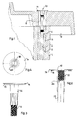
- the reinforcement bar is 2 with the threaded sleeve 4 thereon by grout 5 with the casing stone 1 to one Unit connected. It is understood that in a diagonal arrangement with respect of the cuboid-shaped mantle block with at least two reinforcement anchors Threaded sleeves of this type are provided in the prefabricated component.
- a cover plate 8 e.g. from heavy, light or Fiber concrete, fiberglass concrete or metal (sheet metal), attached and points corresponding to the number of recesses 3 of the casing 1 a number of cylindrical openings 9 on.
- a fastening device generally designated 10
- the threaded sleeve 12 carries one with the upper one Pressed perforated disc 14 on the sleeve edge, on the lower surface of which a sealing ring 15 is attached.
- the hole 18 of the perforated disc 14 is large enough to one hand in the Over the head of the screw 11 exposed part of the internal thread
- the press connection between the screw 11 and the threaded sleeve 12 is particularly resilient in that the two parts are first partially screwed onto one another before the pressing operation and then the threaded sections that are in screw engagement are pressed together.
- the load-bearing capacity of the fastening device 10 achieved in this way readily allows a prefabricated chimney component, which is also as high as a storey, to be attached to eyebolts or support screws screwed into the threaded sleeve 12. In principle, however, it is also sufficient to connect the threaded sleeve to the screw by pressing in sections that have no thread. In the state shown in FIG.
- the sealing ring 15 is pressed against the upper side of the cover plate 8 by the tightened threaded sleeve 12 via the perforated disk 14, so that penetration of moisture into the opening 9 is prevented.
- penetration of moisture through the hole 18 can also be prevented by a sealing cap, not shown, which is snapped over the edge of the perforated disk 14, or by a sealing plug pressed into the thread of the threaded sleeve 12.
- the threaded sleeve 4 and the second threaded sleeve 12 are each the same Components, namely internally threaded sleeves with identical dimensions are.
- the exemplary embodiment shown is thus the threaded sleeve 4 with the perforated disk 14 and the sealing ring 15 and in the threaded sleeve 12 with perforated disc 14 and sealing ring 15 to be identical in the course of production trained units.
- the second threaded sleeve can also be connected to the screw other than by pressing, e.g. by Welding or gluing, or can be carried out directly in one piece with it.
- the perforated disc does not necessarily have to be supported on the top of the cover plate but can also refer to a paragraph within the corresponding offset breakthrough or directly on the wall of the conical downward support tapered breakthrough.
- the hexagon socket on Screw head instead of the hexagon socket on Screw head also an external hexagon that can be accommodated in the threaded sleeve be provided or the actuation of the screw directly by one on the Threaded sleeve self-made tool surface.
Landscapes
- Engineering & Computer Science (AREA)
- Chemical & Material Sciences (AREA)
- Combustion & Propulsion (AREA)
- Mechanical Engineering (AREA)
- General Engineering & Computer Science (AREA)
- Connection Of Plates (AREA)
- Arc Welding In General (AREA)
- Chimneys And Flues (AREA)
Priority Applications (1)
| Application Number | Priority Date | Filing Date | Title |
|---|---|---|---|
| DE20220700U DE20220700U1 (de) | 2001-03-26 | 2002-03-22 | Vorrichtung zur Befestigung einer Abdeckplatte an einem Kaminkopf |
Applications Claiming Priority (2)
| Application Number | Priority Date | Filing Date | Title |
|---|---|---|---|
| DE20105334U DE20105334U1 (de) | 2001-03-26 | 2001-03-26 | Vorrichtung zur Befestigung einer Abdeckplatte an einem Kaminkopf |
| DE20105334U | 2001-03-26 |
Publications (2)
| Publication Number | Publication Date |
|---|---|
| EP1248042A1 true EP1248042A1 (fr) | 2002-10-09 |
| EP1248042B1 EP1248042B1 (fr) | 2006-06-28 |
Family
ID=7954928
Family Applications (1)
| Application Number | Title | Priority Date | Filing Date |
|---|---|---|---|
| EP02006447A Expired - Lifetime EP1248042B1 (fr) | 2001-03-26 | 2002-03-22 | Dispositif pour la fixation d'une plaque de couverture sur une cheminée |
Country Status (3)
| Country | Link |
|---|---|
| EP (1) | EP1248042B1 (fr) |
| AT (1) | ATE331916T1 (fr) |
| DE (2) | DE20105334U1 (fr) |
Citations (4)
| Publication number | Priority date | Publication date | Assignee | Title |
|---|---|---|---|---|
| US3922831A (en) * | 1973-04-16 | 1975-12-02 | Artur Fischer | Expansion anchor for mounting objects at an adjustable distance from a support structure |
| DE8901153U1 (de) * | 1988-05-07 | 1989-05-11 | Betonwerke Heinrich Heß KG Zweigniederlassung Nürnberg, 8500 Nürnberg | Als Fertigteil ausgebildeter Schornsteinkopf |
| DE29716227U1 (de) | 1997-09-10 | 1997-10-30 | Erlus Baustoffwerke AG, 84088 Neufahrn | Kaminkopf mit daran durch Schrauben befestigbarer Abdeckplatte und Bausatz hierfür |
| DE19710421A1 (de) * | 1996-06-14 | 1998-02-12 | Betonwerke Heinrich Hes Kg Zwe | Distanz- und Haltevorrichtung für eine Abdeckplatte eines Schornsteinkopfes |
-
2001
- 2001-03-26 DE DE20105334U patent/DE20105334U1/de not_active Expired - Lifetime
-
2002
- 2002-03-22 EP EP02006447A patent/EP1248042B1/fr not_active Expired - Lifetime
- 2002-03-22 DE DE50207350T patent/DE50207350D1/de not_active Expired - Lifetime
- 2002-03-22 AT AT02006447T patent/ATE331916T1/de active
Patent Citations (4)
| Publication number | Priority date | Publication date | Assignee | Title |
|---|---|---|---|---|
| US3922831A (en) * | 1973-04-16 | 1975-12-02 | Artur Fischer | Expansion anchor for mounting objects at an adjustable distance from a support structure |
| DE8901153U1 (de) * | 1988-05-07 | 1989-05-11 | Betonwerke Heinrich Heß KG Zweigniederlassung Nürnberg, 8500 Nürnberg | Als Fertigteil ausgebildeter Schornsteinkopf |
| DE19710421A1 (de) * | 1996-06-14 | 1998-02-12 | Betonwerke Heinrich Hes Kg Zwe | Distanz- und Haltevorrichtung für eine Abdeckplatte eines Schornsteinkopfes |
| DE29716227U1 (de) | 1997-09-10 | 1997-10-30 | Erlus Baustoffwerke AG, 84088 Neufahrn | Kaminkopf mit daran durch Schrauben befestigbarer Abdeckplatte und Bausatz hierfür |
Also Published As
| Publication number | Publication date |
|---|---|
| ATE331916T1 (de) | 2006-07-15 |
| DE20105334U1 (de) | 2001-05-23 |
| DE50207350D1 (de) | 2006-08-10 |
| EP1248042B1 (fr) | 2006-06-28 |
Similar Documents
| Publication | Publication Date | Title |
|---|---|---|
| EP2085521B1 (fr) | Ancrage de terre ou de rocher doté d'une articulation de tirant d'ancrage composée d'un ou plusieurs éléments individuels ayant une formation de tête d'ancrage protégée contre la corrosion | |
| DE69928053T2 (de) | Methode zum Stellen von Transportbeton und Schalungseinheit, die in dieser Methode benutzt wird | |
| DE2053443C3 (de) | Bauwerk | |
| DE2243102A1 (de) | Tragstuetze fuer aufgestaenderte fussboeden | |
| EP0475216B1 (fr) | Dispositif d'assemblage entre des poutres et des noeuds d'une structure tridimensionelle | |
| DE69635317T2 (de) | Schienensystem | |
| DE4210488A1 (de) | Verbindungseinrichtung für ein insbesondere rohrförmiges Bauteil | |
| EP2149716A2 (fr) | Dispositif de raccordement d'une tige filetée sur des éléments en acier | |
| DE202011003315U1 (de) | Verbindungsvorrichtung | |
| DE4341329A1 (de) | Eingußdübel | |
| AT505689B1 (de) | Verfahren zur montage bzw. zum einbringen eines hohlkörpers in eine betonwand oder betondecke sowie eine installationsdose mit montage-hilfselement | |
| EP1248042A1 (fr) | Dispositif pour la fixation d'une plaque de couverture sur une cheminée | |
| DE3301478C2 (de) | Vorrichtung zum Befestigen eines rohr- oder stangenförmigen Bauteils an einer Montagefläche | |
| DE20220700U1 (de) | Vorrichtung zur Befestigung einer Abdeckplatte an einem Kaminkopf | |
| EP0722026B1 (fr) | Dispositif pour la fixation d'un élément de construction en forme de plaque sur un mur ou similaire | |
| DE19928757A1 (de) | Montageträgersystem und Verfahren zur Montage eines Fertigbauteils an einem Gebäudeteil | |
| EP1847666A1 (fr) | Dispositif d'ancrage pour lier des planches de coffrage | |
| DE4344344A1 (de) | Kamin mit mehreren, durch Verbindungsanordnungen biegesteif miteinander verbundenen Kaminelementen | |
| EP3983625A1 (fr) | Noeud d'échafaudage, rosette d'échafaudage, tige d'échafaudage et montant d'échafaudage, et procédé de fabrication pour une rosette d'échafaudage | |
| DE2734520C3 (de) | Schalungszuganker aus Kunststoff | |
| DE4438602C1 (de) | Maueranker | |
| DE102018107933A1 (de) | Auslegerarm mit innen liegender Rohrhalterverschraubung | |
| EP0480094A1 (fr) | Support pour coffrage de béton | |
| DE4418710C2 (de) | Verbindung für mit Zugankern versehene Hausschornsteinelemente | |
| DE102022114961A1 (de) | Anschlussvorrichtung, Deckenschalungssystem mit Anschlussvorrichtung sowie Verfahren zur Herstellung einer Deckenschalung |
Legal Events
| Date | Code | Title | Description |
|---|---|---|---|
| PUAI | Public reference made under article 153(3) epc to a published international application that has entered the european phase |
Free format text: ORIGINAL CODE: 0009012 |
|
| AK | Designated contracting states |
Kind code of ref document: A1 Designated state(s): AT BE CH CY DE DK ES FI FR GB GR IE IT LI LU MC NL PT SE TR |
|
| AX | Request for extension of the european patent |
Free format text: AL;LT;LV;MK;RO;SI |
|
| 17P | Request for examination filed |
Effective date: 20020919 |
|
| AKX | Designation fees paid |
Designated state(s): AT BE CH CY DE DK ES FI FR GB GR IE IT LI LU MC NL PT SE TR |
|
| AXX | Extension fees paid |
Extension state: SI Payment date: 20021120 |
|
| 17Q | First examination report despatched |
Effective date: 20040805 |
|
| RAP1 | Party data changed (applicant data changed or rights of an application transferred) |
Owner name: ERLUS AKTIENGESELLSCHAFT |
|
| GRAP | Despatch of communication of intention to grant a patent |
Free format text: ORIGINAL CODE: EPIDOSNIGR1 |
|
| GRAS | Grant fee paid |
Free format text: ORIGINAL CODE: EPIDOSNIGR3 |
|
| GRAA | (expected) grant |
Free format text: ORIGINAL CODE: 0009210 |
|
| AK | Designated contracting states |
Kind code of ref document: B1 Designated state(s): AT BE CH CY DE DK ES FI FR GB GR IE IT LI LU MC NL PT SE TR |
|
| AX | Request for extension of the european patent |
Extension state: SI |
|
| PG25 | Lapsed in a contracting state [announced via postgrant information from national office to epo] |
Ref country code: IT Free format text: LAPSE BECAUSE OF FAILURE TO SUBMIT A TRANSLATION OF THE DESCRIPTION OR TO PAY THE FEE WITHIN THE PRESCRIBED TIME-LIMIT;WARNING: LAPSES OF ITALIAN PATENTS WITH EFFECTIVE DATE BEFORE 2007 MAY HAVE OCCURRED AT ANY TIME BEFORE 2007. THE CORRECT EFFECTIVE DATE MAY BE DIFFERENT FROM THE ONE RECORDED. Effective date: 20060628 Ref country code: FI Free format text: LAPSE BECAUSE OF FAILURE TO SUBMIT A TRANSLATION OF THE DESCRIPTION OR TO PAY THE FEE WITHIN THE PRESCRIBED TIME-LIMIT Effective date: 20060628 Ref country code: IE Free format text: LAPSE BECAUSE OF FAILURE TO SUBMIT A TRANSLATION OF THE DESCRIPTION OR TO PAY THE FEE WITHIN THE PRESCRIBED TIME-LIMIT Effective date: 20060628 Ref country code: GB Free format text: LAPSE BECAUSE OF FAILURE TO SUBMIT A TRANSLATION OF THE DESCRIPTION OR TO PAY THE FEE WITHIN THE PRESCRIBED TIME-LIMIT Effective date: 20060628 Ref country code: NL Free format text: LAPSE BECAUSE OF FAILURE TO SUBMIT A TRANSLATION OF THE DESCRIPTION OR TO PAY THE FEE WITHIN THE PRESCRIBED TIME-LIMIT Effective date: 20060628 |
|
| REG | Reference to a national code |
Ref country code: GB Ref legal event code: FG4D Free format text: NOT ENGLISH |
|
| REG | Reference to a national code |
Ref country code: CH Ref legal event code: EP |
|
| REG | Reference to a national code |
Ref country code: CH Ref legal event code: NV Representative=s name: FIAMMENGHI-FIAMMENGHI |
|
| REG | Reference to a national code |
Ref country code: IE Ref legal event code: FG4D Free format text: LANGUAGE OF EP DOCUMENT: GERMAN |
|
| REF | Corresponds to: |
Ref document number: 50207350 Country of ref document: DE Date of ref document: 20060810 Kind code of ref document: P |
|
| PG25 | Lapsed in a contracting state [announced via postgrant information from national office to epo] |
Ref country code: SE Free format text: LAPSE BECAUSE OF FAILURE TO SUBMIT A TRANSLATION OF THE DESCRIPTION OR TO PAY THE FEE WITHIN THE PRESCRIBED TIME-LIMIT Effective date: 20060928 Ref country code: DK Free format text: LAPSE BECAUSE OF FAILURE TO SUBMIT A TRANSLATION OF THE DESCRIPTION OR TO PAY THE FEE WITHIN THE PRESCRIBED TIME-LIMIT Effective date: 20060928 |
|
| PG25 | Lapsed in a contracting state [announced via postgrant information from national office to epo] |
Ref country code: ES Free format text: LAPSE BECAUSE OF FAILURE TO SUBMIT A TRANSLATION OF THE DESCRIPTION OR TO PAY THE FEE WITHIN THE PRESCRIBED TIME-LIMIT Effective date: 20061009 |
|
| PG25 | Lapsed in a contracting state [announced via postgrant information from national office to epo] |
Ref country code: PT Free format text: LAPSE BECAUSE OF FAILURE TO SUBMIT A TRANSLATION OF THE DESCRIPTION OR TO PAY THE FEE WITHIN THE PRESCRIBED TIME-LIMIT Effective date: 20061128 |
|
| NLV1 | Nl: lapsed or annulled due to failure to fulfill the requirements of art. 29p and 29m of the patents act | ||
| ET | Fr: translation filed | ||
| GBV | Gb: ep patent (uk) treated as always having been void in accordance with gb section 77(7)/1977 [no translation filed] |
Effective date: 20060628 |
|
| REG | Reference to a national code |
Ref country code: IE Ref legal event code: FD4D |
|
| PLBE | No opposition filed within time limit |
Free format text: ORIGINAL CODE: 0009261 |
|
| STAA | Information on the status of an ep patent application or granted ep patent |
Free format text: STATUS: NO OPPOSITION FILED WITHIN TIME LIMIT |
|
| 26N | No opposition filed |
Effective date: 20070329 |
|
| PG25 | Lapsed in a contracting state [announced via postgrant information from national office to epo] |
Ref country code: MC Free format text: LAPSE BECAUSE OF NON-PAYMENT OF DUE FEES Effective date: 20070331 |
|
| PG25 | Lapsed in a contracting state [announced via postgrant information from national office to epo] |
Ref country code: GR Free format text: LAPSE BECAUSE OF FAILURE TO SUBMIT A TRANSLATION OF THE DESCRIPTION OR TO PAY THE FEE WITHIN THE PRESCRIBED TIME-LIMIT Effective date: 20060929 |
|
| PGFP | Annual fee paid to national office [announced via postgrant information from national office to epo] |
Ref country code: CH Payment date: 20080320 Year of fee payment: 7 |
|
| PGFP | Annual fee paid to national office [announced via postgrant information from national office to epo] |
Ref country code: LU Payment date: 20080320 Year of fee payment: 7 |
|
| PGFP | Annual fee paid to national office [announced via postgrant information from national office to epo] |
Ref country code: FR Payment date: 20080314 Year of fee payment: 7 |
|
| PGFP | Annual fee paid to national office [announced via postgrant information from national office to epo] |
Ref country code: BE Payment date: 20080321 Year of fee payment: 7 |
|
| PG25 | Lapsed in a contracting state [announced via postgrant information from national office to epo] |
Ref country code: CY Free format text: LAPSE BECAUSE OF FAILURE TO SUBMIT A TRANSLATION OF THE DESCRIPTION OR TO PAY THE FEE WITHIN THE PRESCRIBED TIME-LIMIT Effective date: 20060628 |
|
| BERE | Be: lapsed |
Owner name: *ERLUS A.G. Effective date: 20090331 |
|
| PG25 | Lapsed in a contracting state [announced via postgrant information from national office to epo] |
Ref country code: TR Free format text: LAPSE BECAUSE OF FAILURE TO SUBMIT A TRANSLATION OF THE DESCRIPTION OR TO PAY THE FEE WITHIN THE PRESCRIBED TIME-LIMIT Effective date: 20060628 |
|
| REG | Reference to a national code |
Ref country code: CH Ref legal event code: PL |
|
| REG | Reference to a national code |
Ref country code: FR Ref legal event code: ST Effective date: 20091130 |
|
| PG25 | Lapsed in a contracting state [announced via postgrant information from national office to epo] |
Ref country code: LI Free format text: LAPSE BECAUSE OF NON-PAYMENT OF DUE FEES Effective date: 20090331 Ref country code: CH Free format text: LAPSE BECAUSE OF NON-PAYMENT OF DUE FEES Effective date: 20090331 |
|
| PG25 | Lapsed in a contracting state [announced via postgrant information from national office to epo] |
Ref country code: BE Free format text: LAPSE BECAUSE OF NON-PAYMENT OF DUE FEES Effective date: 20090331 |
|
| PG25 | Lapsed in a contracting state [announced via postgrant information from national office to epo] |
Ref country code: FR Free format text: LAPSE BECAUSE OF NON-PAYMENT OF DUE FEES Effective date: 20091123 |
|
| PG25 | Lapsed in a contracting state [announced via postgrant information from national office to epo] |
Ref country code: LU Free format text: LAPSE BECAUSE OF NON-PAYMENT OF DUE FEES Effective date: 20090322 |
|
| PGFP | Annual fee paid to national office [announced via postgrant information from national office to epo] |
Ref country code: AT Payment date: 20210318 Year of fee payment: 20 Ref country code: DE Payment date: 20201217 Year of fee payment: 20 |
|
| REG | Reference to a national code |
Ref country code: DE Ref legal event code: R071 Ref document number: 50207350 Country of ref document: DE |
|
| REG | Reference to a national code |
Ref country code: AT Ref legal event code: MK07 Ref document number: 331916 Country of ref document: AT Kind code of ref document: T Effective date: 20220322 |