EP1248070A2 - Procédé pour optimaliser l' exactitude des déformations théoriques d' un objet - Google Patents
Procédé pour optimaliser l' exactitude des déformations théoriques d' un objet Download PDFInfo
- Publication number
- EP1248070A2 EP1248070A2 EP02002889A EP02002889A EP1248070A2 EP 1248070 A2 EP1248070 A2 EP 1248070A2 EP 02002889 A EP02002889 A EP 02002889A EP 02002889 A EP02002889 A EP 02002889A EP 1248070 A2 EP1248070 A2 EP 1248070A2
- Authority
- EP
- European Patent Office
- Prior art keywords
- workpiece
- displacements
- parameters
- test
- changed
- Prior art date
- Legal status (The legal status is an assumption and is not a legal conclusion. Google has not performed a legal analysis and makes no representation as to the accuracy of the status listed.)
- Withdrawn
Links
Images



Classifications
-
- G—PHYSICS
- G01—MEASURING; TESTING
- G01B—MEASURING LENGTH, THICKNESS OR SIMILAR LINEAR DIMENSIONS; MEASURING ANGLES; MEASURING AREAS; MEASURING IRREGULARITIES OF SURFACES OR CONTOURS
- G01B11/00—Measuring arrangements characterised by the use of optical techniques
- G01B11/16—Measuring arrangements characterised by the use of optical techniques for measuring the deformation in a solid, e.g. optical strain gauge
-
- G—PHYSICS
- G01—MEASURING; TESTING
- G01B—MEASURING LENGTH, THICKNESS OR SIMILAR LINEAR DIMENSIONS; MEASURING ANGLES; MEASURING AREAS; MEASURING IRREGULARITIES OF SURFACES OR CONTOURS
- G01B21/00—Measuring arrangements or details thereof, where the measuring technique is not covered by the other groups of this subclass, unspecified or not relevant
- G01B21/32—Measuring arrangements or details thereof, where the measuring technique is not covered by the other groups of this subclass, unspecified or not relevant for measuring the deformation in a solid
Definitions
- the invention relates to a method for optimizing the theoretical Design of a new workpiece.
- Such a computer simulation is then carried out by a practical one Strength tests are checked by means of a computer simulation as a rule Workpiece pre-optimized over several improvement stages as a prototype manufactured and actually subjected to the specified loads.
- the deformations occurring at certain points of the Workpiece surface measured, for example by using strain gauges (DMS) are placed on the corresponding surface points.
- the related structure of a strength test can therefore not need only days, but weeks.
- the strength test then still yields in some places high deformations and therefore also other deformations than by means of Computer simulation precalculated so that the workpiece is again in its Design must be modified, and after the modified workpiece design again a prototype was built and tested in the strength test must become.
- strain gauges always only over a very small area, quasi only selectively, the Play load of the workpiece, and also the Deformation of the workpiece only two-dimensionally, namely in the plane reflect curved surfaces of the tangential plane, the workpiece surface.
- Another disadvantage is the exact location of the measuring point, i.e. the Strain gauge on the workpiece.
- optical measuring methods such as the Moirée method to determine areal deformations.
- the strain is measured using a strain gauge measured on the workpiece surface at the location of the strain gauge, ultimately one Relocation of one point in the area of the strain gauge over another Surface point in the area of the strain gauge, the two points for their Distance to each other the strain is given by the strain gauge, not exactly are determinable.
- optical methods such as speckle interferometry however, it is immediately determined how the relative position of the plurality of Measuring points of the surface within the test area to each other below Load changed.
- Such a shift or shift then usually by means of computer simulation first the loads, ie Tensions, both on the surface and inside the Workpiece, calculated, for example using the finite element method.
- strain gauges In order to be able to establish these correlations, however, are used of strain gauges only the information about the strain at the measuring point in one or two directions, but always in the direction of the workpiece surface, to disposal.
- optical methods can also shift in the third dimension detect, for example the correlation analysis, in particular the gray value correlation analysis, often referred to as intensity-based shift analysis, digital image correlation or digital image cross-correlation.
- test head is either on the test area put on or at least in a fixed position opposite the test area fixed.
- Speckle interferometry is used as an areal optical measurement method used, this results in the additional advantage that - such as described in European patent application 97 952 881 - by means of this Process does not just involve shifting the surface between one Starting state and a stressed state can be determined, but in one unchanged workpiece condition also the shape of the surface of the workpiece can be determined in the test area.
- the shape of the workpiece is based on the determination of the shape the surface in the test areas before determining the displacement under Load - by comparison with those on which the computer simulation is based Shape data of the workpiece - the exact positions of the test areas relative to the workpiece.
- speckle interferometry Measuring head it is also advantageous to carry out speckle interferometry Measuring head to be attached to the surface of the workpiece in the test area divisible, namely a basic measuring head and a measuring head holder, on which the measuring head in a defined position, in particular in a form-fitting manner, is attachable.
- Fig. 1 shows an essentially L-shaped component 1, in this case with three spaced-apart mounting holes 5a, b, c, which is in operation by means of one running through the hole 5c Screw connection should be resilient by means of a force F or F 'or F ", in which certain areas a maximum deflection should not be exceeded.
- test areas 2a, b On the surface of the workpiece.
- the maximum deflection should not be greater than d.
- FIG. 1a The enlarged representation of this test area in FIG. 1a shows how on a measuring head 6 is placed on this test area 2b, three of which are down project a triangular feet 8a, b, c with which the measuring head on the Surface 1a of the workpiece 1 is seated.
- the test area 2b which can be measured by the measuring head, is included rectangular or round as shown and is located within the feet 8a, b, c.
- the measuring head 6 consists of a lower one resting on the workpiece 1 Measuring head holder 6a, which has approximately the shape of a ring, and from which the feet 8a, b, c protrude downward, and the base measuring head 6b, which is the measurement contains performing components and in a defined position on the Measuring head holder 6a is attachable and attachable.
- the base measuring head 6b is not connected to an electrical cable 7 shown electronic evaluation unit connected.
- each of the Test areas 2a, b, c each have a measuring head holder 6a attached and fastened, the rough positioning on the workpiece 1 relative to fixed points, for example, the mounting holes 5a, b, c.
- the Workpiece 1 of the base measuring head 6b successively on the measuring head holders 6a of the test areas 2a, b, c and by means of one in the following described method, the contour of the surface 1a in the test areas 2a, b, c determined one after the other.
- FIG. 4 A detailed representation is shown in FIG. 4, which will be explained later.
- a defined load is introduced, for example the force F at the point of introduction shown and in the direction of introduction shown -
- a defined load is introduced, for example the force F at the point of introduction shown and in the direction of introduction shown -
- a defined load is introduced, for example the force F at the point of introduction shown and in the direction of introduction shown -
- the surface shift in a test area according to computer simulation and according to the measurement can be graphically or mathematically, ie in Form of the specification of the coordinates of the individual to defined measuring points, mostly of a measuring grid, shown within the test area and with each other be compared.
- 3a and b shows the graphic type of representation.
- 3a is for the test area z.
- B. 2b the line grid 9 by the finite element method, which of in color - replaced by different or missing hatching in FIG. 3a - Gradations or color transitions are superimposed.
- FIG. 3a shows the displacement image calculated by means of computer simulation Test area 2b.
- Fig. 3b shows that in the performed deformation using the flat optical method, such as the Speckle interferometry, displacement image shown, again in the form of Color gradations and color transitions, shown here again by the type the hatching or its absence.
- hatching zones i.e. color zones in the usual graphic representation, exist, but their transition areas or boundary lines still exist a different curvature and their middle areas different Have width.
- Such a change in one or more parameters can therefore also be carried out gradually in succession until the per Computer simulation determined shift image of the practically measured Relocation picture - and not just one test area, but all on Existing test areas - so little deviates that the Deviations remain below a specified tolerance value.
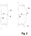
- FIG. 2 The sectional view of FIG. 2 further shows why it is advantageous to use a optical process to work, which is also able to three-dimensional Changes in the position of points on the surface 1a of the workpiece 1 determine:
- the distance a can also change Measuring point to the reference plane E or in a parallel reference plane R, for example that caused by the contact points of the measuring head on the surface 1a is defined, change to a value a ', for example by changing the Curvature of the surface 1a when, for example, the workpiece 1 as in deflects more in the present case.
- the determination of the displacement of a measuring point A - the within the Test area for example 2b can be freely defined and from to 1000 pieces can be defined distributed over the test area - shows Fig. 5.
- Fig. 5 shows a device in which two different ones Illumination directions 8a, 8b illuminations a shift of single measuring point, for example A, in a measuring direction 10b transverse to Direction of observation 9b, therefore generally in the direction of the object surface 1a, determined.
- the direction of observation 9b is usually the Bisector between the two directions of illumination 8a and 8b.
- the reference wave 27 required for this is - in addition to the beam splitter 5 - out the path of the light beams between the laser 3 and the beam splitter 5 preferably in front of the beam splitter 5 by means of a semi-transparent mirror 21 branched off and by means of further mirrors 22a, b again directly and without Object contact directed to the camera 4.
- the mirrors 22, 23 in turn guide the rays in each other Illumination directions 8a, b, which are generally at an acute angle, onto the Measuring point A continues.
- a diffusing lens In the beam path between the beam splitter 5 and the movable mirrors 22, 23 are usually arranged a diffusing lens.
- the fourth serves and every further measuring direction of reducing the influence of incorrect measurements, Signal noise etc. and the improvement of the measurement result.
- Shape i.e. the three-dimensional shape, of the surface 1a of the workpiece 1 in the individual measuring ranges 2a, b, c
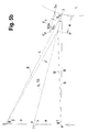
- the procedure is as follows explained with reference to FIG. 5b:
- the basic idea is again by changing the Path length of the light beam from the laser 3 until it strikes the Measuring point A to determine a difference value ⁇ , as with speckle interferometry common.
- the length of the triangle side a as half the distance between the laser 13 and the Camera 14, the angle ⁇ at the point of impact of the observation direction 10a Bisector is exactly in the middle between the laser 13 and the camera 14 and - due to specific changes on the part of the measuring unit or in the beam path of the object waves - is the displacement e in Measuring direction 10, i.e. along the triangle side b.
- the displacement e which is specified as known, in turn specifies in the system of equations 5a a respective difference value ⁇ by which the object reflected wave is offset from a reference beam on the corresponding one Camera point, and thus the factor d in the system of equations Fig. 5a.
- the Measuring direction 10a for example the connection of the in the middle of the Test area 2 located measuring point A with the center of the measuring unit, i.e. the Bisector between the direction of illumination 8 and the direction of observation 9, and the middle between the laser 13 and the camera 14 at the base point 11.
- the displacement e gives the difference value ⁇ for the measuring point A.
- this difference n represents - with respect to the measuring direction 10 - the difference in the distance of the measuring points A and An from the measuring unit.
- the differences in the distances - in particular seen in the measuring direction 10a - of the individual measuring points A .., A n .. of the test area 2 to the measuring unit 12 are determined, but in each case only in the measuring direction 10a.
- the three-dimensional shape of the surface 1a in the measuring area 2 is thus determined.
- FIG 4 shows a sectional view of the measuring head holder 6a and the one on it defined and positively attachable base measuring head 6b.
- the feet are in the front end face 25 of the annular measuring head holder 6a 8a, b, c screwed in evenly over the circumference, so that they fit with their Tips 24 can be placed on the surface 1 a of the workpiece 1.
- the feet 8a, b, c preferably permanent magnets should be formed, since then none mechanical attachment to the surface 1a is necessary, which consists of a Tension belt or the like could exist.
- Dowel pins 24 protrude from the rear end face 16 and into corresponding ones Fitting holes 27 of the base measuring head 6b fit when this on the rear end face 26 of the measuring head holder 6a is placed.
- the measuring head holder 6a has a mounting option for the Base measuring head 6b, in this case in the form of pivot levers 27, the outside the circumference of the annular measuring head holder 6a approximately parallel to whose lateral surface is in the direction of the central axis of the measuring head holder 6a extend and on its rear, projecting beyond the rear end face 26, End, have inward-facing projections that when attached Base measuring head 6b in transverse bores 25 in its lateral surface can snap into place. So that this connection does not come off automatically, they are Swing lever 27 into the latching position of the extensions 26 by means of springs 29 biased.
- the base measuring head 6b can quickly and exactly at any time reproducible on an already arranged on the workpiece 1 and positioned measuring head holder 6a are attached and fastened to the Carrying out the measurements.
Landscapes
- Physics & Mathematics (AREA)
- General Physics & Mathematics (AREA)
- Investigating Strength Of Materials By Application Of Mechanical Stress (AREA)
- Length Measuring Devices By Optical Means (AREA)
Applications Claiming Priority (2)
| Application Number | Priority Date | Filing Date | Title |
|---|---|---|---|
| DE2001105994 DE10105994B4 (de) | 2001-02-09 | 2001-02-09 | Verfahren zum Optimieren der Richtigkeit der theoretisch ermittelten Verformungen eines Werkstückes unter Belastung |
| DE10105994 | 2001-02-09 |
Publications (2)
| Publication Number | Publication Date |
|---|---|
| EP1248070A2 true EP1248070A2 (fr) | 2002-10-09 |
| EP1248070A3 EP1248070A3 (fr) | 2004-02-04 |
Family
ID=7673461
Family Applications (1)
| Application Number | Title | Priority Date | Filing Date |
|---|---|---|---|
| EP02002889A Withdrawn EP1248070A3 (fr) | 2001-02-09 | 2002-02-08 | Procédé pour optimaliser l' exactitude des déformations théoriques d' un objet |
Country Status (2)
| Country | Link |
|---|---|
| EP (1) | EP1248070A3 (fr) |
| DE (1) | DE10105994B4 (fr) |
Cited By (5)
| Publication number | Priority date | Publication date | Assignee | Title |
|---|---|---|---|---|
| CN105890884A (zh) * | 2016-04-07 | 2016-08-24 | 东北大学 | 一种提升机主轴可靠性的分析计算评估方法 |
| CN110378000A (zh) * | 2019-07-11 | 2019-10-25 | 上海理工大学 | 基于强度场的结构静强度设计方法 |
| CN113776807A (zh) * | 2021-10-08 | 2021-12-10 | 中国船舶科学研究中心 | 一种大深度穿舱手轮轴性能测试装置及操作方法 |
| CN114935302A (zh) * | 2022-07-22 | 2022-08-23 | 山东安驰新能源科技有限公司 | 一种电动车差速器第一壳体公差检测装置及检测方法 |
| CN115265366A (zh) * | 2022-07-29 | 2022-11-01 | 华能澜沧江水电股份有限公司 | 物体的变形检测方法、装置、终端设备和存储介质 |
Families Citing this family (7)
| Publication number | Priority date | Publication date | Assignee | Title |
|---|---|---|---|---|
| DE102008038297A1 (de) * | 2008-08-18 | 2010-02-25 | Eads Deutschland Gmbh | System und Verfahren zum Prüfen von Bauteilen |
| CN103994878B (zh) * | 2014-04-17 | 2017-06-16 | 中国航空工业集团公司沈阳飞机设计研究所 | 一种飞机活动翼面的综合试验验证方法 |
| CN104729420A (zh) * | 2015-03-24 | 2015-06-24 | 中国科学院上海技术物理研究所 | 一种测量红外焦平面模块低温形变的装置及方法 |
| DE102016108991A1 (de) * | 2016-05-14 | 2017-11-16 | Technische Universität Darmstadt | Verfahren und Vorrichtung zur Charakterisierung eines Bauteils |
| DE102018005635A1 (de) * | 2018-07-17 | 2020-01-23 | Fachhochschule Aachen | Verfahren zu Qualitätssicherung von Bauteilen aus inhomogenen Werkstoffen durch Bestimmung der lokalen mechanischen und geometrischen Eigenschaften und Erzeugung eines individuellen digitalen Klon |
| CN110376059B (zh) * | 2019-07-11 | 2021-11-19 | 上海理工大学 | 基于静强度的结构全场轻量化定量评价方法 |
| DE102019219387A1 (de) * | 2019-12-11 | 2021-06-17 | MTU Aero Engines AG | Verfahren und vorrichtung zum bestimmen von aufwertefaktoren für dehnungsmessungen an maschinenelementen |
Family Cites Families (2)
| Publication number | Priority date | Publication date | Assignee | Title |
|---|---|---|---|---|
| DE19650325A1 (de) * | 1996-12-04 | 1998-06-10 | Ettemeyer Gmbh & Co Mes Und Pr | Verfahren und Vorrichtung zur Ermittlung von Verformungen und Dehnungen an gekrümmten Körpern |
| US6101450A (en) * | 1997-06-03 | 2000-08-08 | The Trustees Of Columbia University In The City Of New York | Stress analysis using a defect-free four-node finite element technique |
-
2001
- 2001-02-09 DE DE2001105994 patent/DE10105994B4/de not_active Expired - Fee Related
-
2002
- 2002-02-08 EP EP02002889A patent/EP1248070A3/fr not_active Withdrawn
Cited By (7)
| Publication number | Priority date | Publication date | Assignee | Title |
|---|---|---|---|---|
| CN105890884A (zh) * | 2016-04-07 | 2016-08-24 | 东北大学 | 一种提升机主轴可靠性的分析计算评估方法 |
| CN105890884B (zh) * | 2016-04-07 | 2018-05-22 | 东北大学 | 一种提升机主轴可靠性的分析计算评估方法 |
| CN110378000A (zh) * | 2019-07-11 | 2019-10-25 | 上海理工大学 | 基于强度场的结构静强度设计方法 |
| CN113776807A (zh) * | 2021-10-08 | 2021-12-10 | 中国船舶科学研究中心 | 一种大深度穿舱手轮轴性能测试装置及操作方法 |
| CN114935302A (zh) * | 2022-07-22 | 2022-08-23 | 山东安驰新能源科技有限公司 | 一种电动车差速器第一壳体公差检测装置及检测方法 |
| CN114935302B (zh) * | 2022-07-22 | 2022-09-23 | 山东安驰新能源科技有限公司 | 一种电动车差速器第一壳体公差检测装置及检测方法 |
| CN115265366A (zh) * | 2022-07-29 | 2022-11-01 | 华能澜沧江水电股份有限公司 | 物体的变形检测方法、装置、终端设备和存储介质 |
Also Published As
| Publication number | Publication date |
|---|---|
| DE10105994A1 (de) | 2002-09-05 |
| EP1248070A3 (fr) | 2004-02-04 |
| DE10105994B4 (de) | 2004-02-05 |
Similar Documents
| Publication | Publication Date | Title |
|---|---|---|
| EP2040026B1 (fr) | Procédé et système de calibrage d'un appareil de mesure de la forme d'une surface réfléchissante | |
| DE10047211B4 (de) | Verfahren und Vorrichtung zur Positionsbestimmung einer Kante eines Strukturelementes auf einem Substrat | |
| EP2920544A1 (fr) | Procédés de mesure optiques et dispositif de mesure comprenant une tête de mesure pour appréhender une topographie de surface par calibrage de l'orientation de la tête de mesure | |
| EP1248070A2 (fr) | Procédé pour optimaliser l' exactitude des déformations théoriques d' un objet | |
| EP3497409B1 (fr) | Procédé permettant de déterminer la courbure et/ou la torsion d'un guide d'ondes optiques | |
| WO2008012091A2 (fr) | Procédé et dispositif de détermination de l'écart d'une forme réelle de la forme nominale d'une surface optique | |
| DE69921362T2 (de) | Schatten-moire-oberflächentopologieprüfung mit eichproben | |
| DE69406089T2 (de) | Optische achromatische Interferometer vom Typ trilateraler Phasenverschiebung | |
| DE102007063529A1 (de) | Verfahren und Vorrichtung zum optischen Inspizieren einer Oberfläche an einem Gegenstand | |
| DE102010007396A1 (de) | Verfahren und Vorrichtung zum optischen Inspizieren eines Prüflings mit einer zumindest teilweise reflektierenden Oberfläche | |
| DE102019212520A1 (de) | Diffraktives optisches Element für ein Prüfinterferometer | |
| DE2758149C2 (de) | Interferometrisches Verfahren mit λ /4-Auflösung zur Abstands-, Dicken- und/oder Ebenheitsmessung | |
| DE102005042902A1 (de) | Vorrichtung zum Vermessen von Bauteilen und Auswerteeinheit | |
| DE102010037207B3 (de) | Rauheits-Messvorrichtung und -Messverfahren | |
| EP3575741B1 (fr) | Procédé de mesure sans contact d'un bord de pièce à usiner | |
| DE10156431B4 (de) | Verfahren zur Lagebestimmung von Meßpunkten auf einem Objekt | |
| DE102014223747B4 (de) | Vorrichtung und Verfahren zur Vermessung eines Höhenprofils einer Oberfläche unter Verwendung einer länglichen Blende | |
| EP1012534B1 (fr) | Procede et dispositif pour la determination de deformations et d'allongements sur des corps curvilignes | |
| DE10256273B3 (de) | Interferenzoptische Formmesseinrichtung mit Phasenschiebung | |
| DE10126185A1 (de) | Prüfkörper für optoelektronische Bildanalysesysteme | |
| EP4143502B1 (fr) | Système de microscope et procédé de mesure d'une structure de surface d'un échantillon | |
| EP1794572B1 (fr) | Procede d'exploitation d'un systeme interferometrique avec un element de reference pourvu d'une ou plusieurs zones reflechissantes | |
| DE202004020886U1 (de) | Vorrichtung zum Vermessen von Bauteilen und Auswerteeinheit | |
| DE102011077982B4 (de) | Verfahren und Vorrichtung zur optischen Analyse eines Prüflings | |
| DE102004061177B4 (de) | Vorrichtung zum Vermessen von Bauteilen |
Legal Events
| Date | Code | Title | Description |
|---|---|---|---|
| PUAI | Public reference made under article 153(3) epc to a published international application that has entered the european phase |
Free format text: ORIGINAL CODE: 0009012 |
|
| AK | Designated contracting states |
Kind code of ref document: A2 Designated state(s): AT BE CH CY DE DK ES FI FR GB GR IE IT LI LU MC NL PT SE TR |
|
| AX | Request for extension of the european patent |
Free format text: AL;LT;LV;MK;RO;SI |
|
| PUAL | Search report despatched |
Free format text: ORIGINAL CODE: 0009013 |
|
| AK | Designated contracting states |
Kind code of ref document: A3 Designated state(s): AT BE CH CY DE DK ES FI FR GB GR IE IT LI LU MC NL PT SE TR |
|
| AX | Request for extension of the european patent |
Extension state: AL LT LV MK RO SI |
|
| RAP1 | Party data changed (applicant data changed or rights of an application transferred) |
Owner name: DANTEC ETTEMEYER GMBH |
|
| 17P | Request for examination filed |
Effective date: 20040804 |
|
| AKX | Designation fees paid |
Designated state(s): AT BE CH CY DE DK ES FI FR GB GR IE IT LI LU MC NL PT SE TR |
|
| STAA | Information on the status of an ep patent application or granted ep patent |
Free format text: STATUS: THE APPLICATION IS DEEMED TO BE WITHDRAWN |
|
| 18D | Application deemed to be withdrawn |
Effective date: 20060103 |