EP1248363B1 - Steuerung für einen HF-Leistungsgenerator mit geringer Kabellängeempfindlichkeit - Google Patents
Steuerung für einen HF-Leistungsgenerator mit geringer Kabellängeempfindlichkeit Download PDFInfo
- Publication number
- EP1248363B1 EP1248363B1 EP02001370A EP02001370A EP1248363B1 EP 1248363 B1 EP1248363 B1 EP 1248363B1 EP 02001370 A EP02001370 A EP 02001370A EP 02001370 A EP02001370 A EP 02001370A EP 1248363 B1 EP1248363 B1 EP 1248363B1
- Authority
- EP
- European Patent Office
- Prior art keywords
- power
- signal
- feedback signal
- setpoint
- power generator
- Prior art date
- Legal status (The legal status is an assumption and is not a legal conclusion. Google has not performed a legal analysis and makes no representation as to the accuracy of the status listed.)
- Expired - Lifetime
Links
- 230000002829 reductive effect Effects 0.000 title description 3
- 230000035945 sensitivity Effects 0.000 title description 3
- 230000002441 reversible effect Effects 0.000 claims description 20
- 238000000034 method Methods 0.000 claims description 19
- 239000003607 modifier Substances 0.000 claims description 6
- 230000006870 function Effects 0.000 description 21
- 238000012986 modification Methods 0.000 description 11
- 230000004048 modification Effects 0.000 description 11
- 238000010586 diagram Methods 0.000 description 4
- 230000002159 abnormal effect Effects 0.000 description 3
- 230000002411 adverse Effects 0.000 description 2
- 230000007423 decrease Effects 0.000 description 2
- 238000005070 sampling Methods 0.000 description 2
- 238000004088 simulation Methods 0.000 description 2
- 235000013599 spices Nutrition 0.000 description 2
- 239000004743 Polypropylene Substances 0.000 description 1
- 239000004809 Teflon Substances 0.000 description 1
- 229920006362 Teflon® Polymers 0.000 description 1
- 238000004422 calculation algorithm Methods 0.000 description 1
- 238000004364 calculation method Methods 0.000 description 1
- 239000003990 capacitor Substances 0.000 description 1
- 238000007796 conventional method Methods 0.000 description 1
- 238000009434 installation Methods 0.000 description 1
- 230000000670 limiting effect Effects 0.000 description 1
- 230000007774 longterm Effects 0.000 description 1
- 230000007257 malfunction Effects 0.000 description 1
- 238000004519 manufacturing process Methods 0.000 description 1
- 239000000463 material Substances 0.000 description 1
- 238000005259 measurement Methods 0.000 description 1
- 238000012544 monitoring process Methods 0.000 description 1
- 230000010363 phase shift Effects 0.000 description 1
- -1 polypropylene Polymers 0.000 description 1
- 229920001155 polypropylene Polymers 0.000 description 1
- 230000000717 retained effect Effects 0.000 description 1
- 239000000523 sample Substances 0.000 description 1
- 239000004065 semiconductor Substances 0.000 description 1
- 238000012360 testing method Methods 0.000 description 1
Images







Classifications
-
- H—ELECTRICITY
- H03—ELECTRONIC CIRCUITRY
- H03F—AMPLIFIERS
- H03F3/00—Amplifiers with only discharge tubes or only semiconductor devices as amplifying elements
- H03F3/20—Power amplifiers, e.g. Class B amplifiers, Class C amplifiers
- H03F3/21—Power amplifiers, e.g. Class B amplifiers, Class C amplifiers with semiconductor devices only
-
- H—ELECTRICITY
- H03—ELECTRONIC CIRCUITRY
- H03F—AMPLIFIERS
- H03F1/00—Details of amplifiers with only discharge tubes, only semiconductor devices or only unspecified devices as amplifying elements
- H03F1/34—Negative-feedback-circuit arrangements with or without positive feedback
- H03F1/345—Negative-feedback-circuit arrangements with or without positive feedback using hybrid or directional couplers
-
- H—ELECTRICITY
- H03—ELECTRONIC CIRCUITRY
- H03F—AMPLIFIERS
- H03F1/00—Details of amplifiers with only discharge tubes, only semiconductor devices or only unspecified devices as amplifying elements
- H03F1/52—Circuit arrangements for protecting such amplifiers
-
- H—ELECTRICITY
- H03—ELECTRONIC CIRCUITRY
- H03F—AMPLIFIERS
- H03F3/00—Amplifiers with only discharge tubes or only semiconductor devices as amplifying elements
- H03F3/189—High-frequency amplifiers, e.g. radio frequency amplifiers
Definitions
- the present invention relates to controllers for radio frequency (RF) power generators, and more particularly to controllers for RF power generators with reduced cable length sensitivity.
- RF radio frequency
- FIG. 1 shows a typical radio frequency (RF) power generator 10 that includes a power module 11 and a controller 12.
- the power module 11 receives signals from RF exciter 14, amplifies the signals, and delivers the signals to a load 16.
- the power module 11 includes a driver 18 and a final amplifier 20.
- the power module 11 receives DC power through a cable 24 that is coupled to a remote battery 26 with a ground return.
- the cable 24 may have substantial distributed impedance.
- the controller 12 includes an amplifier 30, a frequency compensation capacitor 34, and a buffer 38.
- the controller 12 receives control inputs 40 and feedback signals 42 and produces a control voltage 44 that varies the gain of the driver 18.
- the controller 12 regulates output power during normal conditions and protects the power module 11 during abnormal conditions.
- the controller 12 employs negative feedback to diminish an error between the greatest feedback signal and a reference input that has been selected according to nominal operating levels of the feedback transducers.
- Feedback signals from the power module 11 include forward and reverse power signals 50 and 52 that are generated by RF detectors 54 and 56.
- the detectors 54 and 56 are typically coupled to sampling arms of a directional coupler 60.
- Other feedback signals include a temperature signal 62 from a thermistor 64 that is thermally coupled to the final amplifier 20.
- Differential voltage feedback signals 66 and 70 are proportional to DC input current to the power module 11 (through a current-sampling resistor 72).
- a drive signal 74 feeds back the drive current to the final amplifier 20.
- a feedback signal 76 feeds back the control voltage 44 that is supplied to the driver 18.
- the controller 12 increases the control signal 44 until the forward power signal 50 becomes approximately equal to a reference setpoint. Under abnormal conditions, the other feedback signals increase and exceed the forward power signal 50. For example, the reverse power signal 52 increases when the load 16 becomes mismatched or is removed. Increasing the drive signal 44 without a corresponding increase in the forward power signal 50 indicates load mismatch or malfunction of the final amplifier 20. Excessive control voltage for a given output power typically corresponds to a problem in the driver 18. Low DC input current indicates load mismatch, a faulty driver 18, or a faulty final amplifier 20. High DC input current or a high final amplifier 20 temperature indicates that the controller 12 should reduce forward power demands on the power module 11. When one or more of these conditions occur, the controller 12 reduces the drive signal 44 to the power module 11 to keep the largest feedback signal approximately equal to the reference setpoint.
- the RF power generator control system 100 includes a power module 102, a RF sensor 104, a load 106, and a controller 108.
- the power module 102 generates power module feedback signals 109 (such as PA supply current 110 and device temperature 114).
- the RF sensor 104 generates RF sensor feedback signals 115 (such as forward and reverse power 116 and 118).
- the power module feedback signals 109, the RF sensor feedback signals 115, and an external setpoint signal 120 are input to the controller 108.
- the controller 108 generates a power module setpoint signal 124 that is input to the power module 102.
- the power module setpoint signal 124 controls the forward power output by the power module 102.
- the basic control technique is to provide negative feedback signals from various detectors (such as the forward power 116, the reverse power 118, the PA supply current 110, and the device temperature 114).
- various detectors such as the forward power 116, the reverse power 118, the PA supply current 110, and the device temperature 114.
- the controller 108 increases or decreases the power module setpoint signal 124 to regulate the forward power 116 of the power module 102.
- another feedback signal for example the supply current 110 to the power amplifier in the power module 102, dominates the forward power feedback 116. This will cause the controller 108 to reduce the power module setpoint 124.
- the power module 102 reduces the forward power delivered to the load 106.
- This control technique is effective in protecting the generator from adverse loads but does not give repeatable performance when the cable length L between the power module 102 (the RF sensor 104) and the load 106 is varied.
- the change in the cable length L introduces a phase shift that may cause a high impedance load to be transformed into a low impedance load.
- the changes in the load impedance cause an increase or decrease in the current draw of the power amplifier in the power module 102.
- the impedance shift causes the supply current limiting loop of the power amplifier to reduce or increase the power module setpoint 124. This in turn causes the RF power generator control system 100 to deliver less or more power than the unphase-shifted case even though the voltage standing wave ratio (VSWR) has not changed.
- VSWR voltage standing wave ratio
- US 5,196,808 A discloses a radio frequency transmitter comprising a processor.
- the processor receives an external setpoint signal, e.g. high, medium, low power, from a memory and also receives forward and reverse power feedback. If the forward power feedback signal indicates that the forward power is less than or equal to a threshold voltage, the processor sends commands to turn off the RF power amplifier.
- an external setpoint signal e.g. high, medium, low power
- EP 0 982 852 A2 shows a radio frequency power amplifier system which is directed to monitoring the system and providing protection for the system. It comprises an amplifier, which changes the magnitude of an input signal received by an input terminal. The power signal is then divided and amplified by a number of power amplifiers and again combined by a combiner, before being applied to a load. The forward and the reverse power feedback signals are received by couplers and processed back to a microcontroller. If the forward power feedback signal exceeds a reference value, an interrupt signal is sent to the microcontroller which then enters a fault routine to turn the power amplifier off.
- a radio frequency (RF) power generator system according to the invention is as defined in claim 1.
- the controller selects a lesser value between the forward power limit and the external setpoint signal.
- the power generator includes a RF sensor that generates the forward power feedback signal and the reverse power feedback signal.
- the power generator includes a power module that generates a supply current feedback signal and a temperature feedback signal that are output to the controller.
- the setpoint modifier and the controller are integrated.
- the setpoint modifier includes one of a lookup table and a formula for calculating the forward power limit.
- the formula determines the forward power limit based on the forward and reverse power feedback signals and maximum power dissipation.
- FIG. 1 is a block diagram of an RF power generator according to the prior art that includes a controller
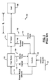
- FIG. 2 is a simplified block diagram of an RF power generator according to the prior art
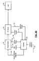
- FIG. 3A is a block diagram of an RF power generator control system according to the present invention.
- FIG. 3B is a block diagram of a RF power generator control system with a combined controller and external setpoint modification module
- FIG. 4 illustrates steps for determining forward power as a function of gamma or VSWR
- FIG. 5B is a graph depicting power dissipation as a function of load phase for various VSWR
- FIG. 6 is a graph depicting power dissipation as a function of forward power for a VSWR of 1:1;
- FIG. 7 is a graph depicting power dissipation as a function of forward power or a VSWR of 2:1;
- FIG. 8 is a graph depicting power dissipation as a function of forward power for a VSWR of 3:1;
- FIG. 9 is a graph depicting power dissipation as a function of forward power for a VSWR of infinity:1;
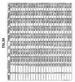
- FIG. 10A is a data table containing quadratic and linear model parameters for worst case loads at various VSWR;
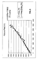
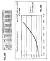
- FIG. 10B is a plot that parameterizes the power dissipation "m" parameter as a function of gamma.
- FIG. 11 is a Smith Chart that shows the resulting forward power versus load for various VSWR for the RF power generator control system.
- the power generator control system 100 includes the power module 102, the RF sensor 104, the load 106, and the controller 108.
- the power module 102 generates power module feedback signals 109 (such as the PA supply current 110 and the device temperature 114).
- the RF sensor 104 generates the RF sensor feedback signals 115 (such as the forward and reverse power 116 and 118).
- the power module feedback signals 109, the RF sensor feedback signals 115, and the external setpoint signal 120 are input to the controller 108.
- the controller 108 generates the power module setpoint signal 124 that is input to the power module 102.
- An improved RF power generator control system 200 includes an external setpoint modification module 204 that calculates a forward power limit based on VSWR or gamma and selects the lesser of the forward power limit and the external setpoint.
- the external setpoint signal 120 is input to the external setpoint modification module 204.
- the forward and reverse power feedback signals 116 and 118 are input to the external setpoint modification module 204.
- the external setpoint modification module 204 generates a modified external setpoint signal 208 that is input to a controller 210.
- the modified external setpoint signal 208 is equal to the lesser of the forward power limit and the external setpoint.
- the external setpoint modification module 204 is preferably implemented as an algorithm that is executed by a processor and memory.
- the external setpoint modification module 204 may also be implemented as a hardwired circuit and/or integrated with the controller 210 (as shown in FIG. 3B ).
- the external setpoint modification module 204 employs a formula or look-up table that is derived from SPICE simulations or limit-test data as will be described further below.
- the formula or look-up table defines a forward power limit for a given VSWR (or gamma).
- the formula or look-up table is used to calculate the forward power limit in real time based on the actual VSWR (or gamma).
- the calculated forward power limit is used at the input of the feedback control system.
- the setpoint modification module 204 chooses the lesser of the external setpoint signal or the forward power limit as the setpoint for the RF generator control system 200. Alternately, the setpoint modification module 204 can calculate the forward power limit and transmit the forward power limit and the external setpoint to the controller 210 for selection.
- the power amplifier (PA) supply current 110, the device temperature 114 and other signals are retained to allow the controller 210 to react to abnormal conditions such as component failure.
- the forward power limit remains constant for a given VSWR regardless of the phase length between the power module 102 and the load 106. Note that the distance L is shown between the RF sensor 104 and the load 106 because the distance between the power module 102 and the RF sensor 104 is fixed.
- the present invention improves the repeatability of the forward power that is supplied by the RF generator regardless of the cable length L or other phase variations.
- the RF generator is limited to deliver the power that it is capable of for the worst-case load. Since the load impedance changes more quickly than variables such as the supply current 110 to the power amplifier and device temperature 114, the RF generator control system 200 reacts more quickly to the load 106. As a result, the RF generator sees lower supply current to the power amplifier and lower device temperature, which improves the long-term reliability of the RF generator.
- step 250 the worst-case stress data is collected as a function of power setpoint and load.
- various cable lengths are used to determine the highest power dissipation in the power amplifier.
- the power dissipation is plotted as a function of the forward power.
- the worst-case stress data can be determined using other system voltages and currents in addition to power dissipation. For example, power amplifier current, power amplifier supply voltage, power amplifier transistor peak output voltage and other system voltages and currents can be employed.
- Load phase refers to the number of degrees around the Smith Chart. 360° around the Smith Chart corresponds to one-half wavelength.
- the frequency of operation and the velocity factor of the cable material are employed.
- Teflon cable once around the Smith Chart is equal to 25.19 feet.
- the one-half wavelength distance is equal to 23.95 feet (24 feet is often a good approximation).
- FIG. 5B is a graph illustrating power dissipation in the power amplifier as a function of load phase for various VSWRs. In this example, the worst power dissipation occurred near 0 degrees. Different power amplifiers will have different results.
- the identified load is used to plot power dissipation as a function of forward power. Equations are fit to the power dissipation vs. forward power data in step 254.
- step 258 the coefficients of the family of equations are parameterized as a function of VSWR.
- the "m" parameter of the linear equations define a three-dimensional function - P diss (power amplifier dissipation) as a function of forward power and VSWR (or gamma).
- step 262 the formula or look-up table is generated.
- the slope (m) is graphed as a function of the reflection coefficient ( ⁇ ) and a curve is fit to this data to generate the function m( ⁇ ) as is shown in FIG. 10B .
- the b parameter does not change much with ⁇ , so b can be kept constant. b can also be adjusted to make the model more conservative and to provide more power dissipation headroom.
- P dmax (3000, 0) 1010W - estimated maximum dissipation into a 50 ohm load at 3000W (actual is 822W).
- P dmax (3000, 0.2) 1144W - estimated max dissipation into a 1.5:1 at 3000W (actual is 1189W).
- P dmax (2400, 0.333) 1162W - estimated max dissipation into a 2:1 VSWR at 2400W (actual is 1100W).
- P dmax (1800, 0.5) 1230W - estimated max dissipation into a 3:1 VSWR at 1800W (actual is 1131W).
- P dmax (600, 1) 1106W - estimated max dissipation into a infinite VSWR at 600W (actual is 991W).
- the RF generator is insensitive to phase variation.
- the forward and reflected power signal can be provided by a directional coupler as is illustrated in FIG. 1 , a voltage/current probe or any other suitable source.
- Input data for determining the formula or look-up table can be determined using SPICE simulation or experimental measurements.
- the formula or look-up table can be determined by using a number of linear fitting techniques such as least squares or nonlinear fitting techniques.
- the calculation of the forward power limit can be performed by an analog, digital signal processor (DSP), digital computer or any other suitable device.
- DSP digital signal processor
- the closed loop control can be analog or digital.
Landscapes
- Engineering & Computer Science (AREA)
- Power Engineering (AREA)
- Amplifiers (AREA)
- Control Of Electrical Variables (AREA)
- Transmitters (AREA)
- Supply And Distribution Of Alternating Current (AREA)
- Plasma Technology (AREA)
Claims (19)
- Ein Radiofrequenz(RF)-Energiegeneratorsystem umfassend
einen Energiegenerator zur Erzeugung eines RF-Energiesignals, das an eine Last abgegeben wird, Sensormittel (104) zur Erzeugung eines Vor-Leistungsrückkopplungssignals (116) und eines Rück-Leistungsrückkopplungssignals (118),
einen Regler (210) für den Empfang des Vor-Leistungsrückkopplungssignals (116) und des Rück-Leistungsrückkopplungssignals (118) und zur Erzeugung eines Sollwertsignals (124) zur Steuerung des Energiegenerators, und
einen Sollwertmodifizierer (204) zum Empfangen des Vor-Leistungsrückkopplungssignals (116), des Rück-Leistungsrückkopplungssignals (118) und eines externen Sollwertsignals (120),
dadurch gekennzeichnet,
dass der Sollwertmodifizierer (204) zur Berechnung eines Vor-Leistungsgrenzwerts, der auf dem Vorwärts- und Rück-Leistungsrückkopplungssignal (116, 118) basiert, und zur Ausgabe eines modifizierten Sollwertsignals (208) an den Regler (210), das auf dem Vor-Leistungsgrenzwert oder dem externen Sollwertsignal (120) basiert, ausgebildet ist. - RF-Energiegeneratorsystem gemäß Anspruch 1, wobei der Regler (210) zur Auswahl eines niedrigeren Werts des Vor-Leistungsgrenzwerts und des externen Sollwertsignals (12) als externes modifiziertes Sollwertsignal (208) ausgebildet ist.
- RF-Energiegeneratorsystem gemäß Anspruch 2, wobei der Energiegenerator einen RF-Sensor (104) zur Erzeugung des Vor-Leistungsrückkopplungssignals (116) und des Rück-Leistungsrückkopplungssignals (118) umfasst.
- RF-Energiegeneratorsystem gemäß Anspruch 3, wobei der Energiegenerator ein Leistungsmodul (102) zur Erzeugung eines Versorgungsstromrückkopplungssignals (110) und eines Temperaturrückkopplungssignals (114), die an den Regler (210) abgegeben werden, umfasst.
- RF-Energiegeneratorsystem gemäß Anspruch 3, wobei der Sollwertmodifizierer und der Regler ein Bauteil (210') sind.
- RF-Energiegeneratorsystem gemäß Anspruch 5, wobei der Sollwertmodifizierer (210') eine Nachschlagtabelle und eine Formel zur Berechnung des Durchlassleistungsgrenzwerts aus den Vor- und Rück-Leistungsrückkopplungssignalen (116, 118) umfasst.
- RF-Energiegeneratorsystem gemäß Anspruch 6, wobei der Energiegenerator einen Leistungsverstärker umfasst und wobei die Formel den Vor-Leistungsgrenzwert, basierend auf Gamma und wenigstens einem der nachfolgenden Werte, nämlich dem maximalen Leistungsverlustversorgungsstrom, der Versorgungsspannung oder der Ausgabespannung des Leistungsverstärkers, bestimmt.
- Verfahren zur Steuerung eines Radiofrequenz(RF)-Energiegenerators, der ein RF-Leistungssignal für eine Last erzeugt, die folgenden Schritte umfassend Abtasten eines Vor-Leistungsrückkopplungssignals (116), Abtasten eines Rück-Leistungsrückkopplungssignals (118), Empfangen eines externen Sollwertsignals (120), gekennzeichnet durch die Schritte:Berechnen eines Vor-Leistungsgrenzwerts basierend auf dem Vor- und dem Sperrleistungsrückkopplungssignal (116, 118) undSteuern des RF-Energiegenerators basierend auf dem Vor-Leistungsgrenzwert oder dem externen Sollwertsignal (120).
- Verfahren gemäß Anspruch 8, ferner den folgenden Schritt umfassend:Auswählen eines niedrigeren Werts des Vor-Leistungsgrenzwerts und des externen Sollwertgrenzwertsignals (120), undÜbertragung des niedrigeren Werts an ein Leistungsmodul (102).
- Verfahren gemäß Anspruch 9, ferner den folgenden Schritt umfassend:Erzeugen des Vor-Leistungsrückkopplungssignals (116) und des Rück-Leistungsrückkopplungssignals (118) unter Verwendung eines RF-Sensors (104) des RF-Energiegenerators.
- Verfahren gemäß Anspruch 10, ferner den folgenden Schritt umfassend:Erzeugen eines Versorgungsstromrückkopplungssignals (110) und eines Temperaturrückkopplungssignals (114) unter Verwendung des Leistungsmoduls des RF-Energiegenerators.
- Verfahren gemäß Anspruch 8, wobei der Vor-Leistungsgrenzwert unter Verwendung einer Nachschlagtabelle oder einer Formel berechnet wird.
- Verfahren gemäß Anspruch 12, wobei der Energiegenerator einen Leistungsverstärker umfasst und wobei die Formel eine Beziehung zwischen Gamma, dem Vor-Leistungsgrenzwert und wenigstens einem der folgenden Werte, nämlich dem Leistungsverlust, dem Versorgungsstrom, der Versorgungsspannung oder der Ausgabespannung des Leistungsverstärkers, bestimmt.
- Verfahren gemäß Anspruch 13, wobei die Formel durcha) Bestimmen der Kabellänge zwischen 0 und einer halben Wellenlänge mit dem höchsten Leistungsverlust bei einem ersten Stehwellenverhältnis (VSWR),b) Wiederholen von Schritt (a) für eine Mehrzahl von Stehwellenverhältnissen (VSWR),c) Bestimmen einer mathematischen Annäherung des Leistungsverlusts für jedes der Stehwellenverhältnisse (VSWR) als eine Funktion einer Durchlassleistung für die Kabellänge, die den höchsten Leistungsverlust aufweist, undd) Parametrieren der mathematischen Annäherung als eine Funktion aus dem Stehwellenverhältnis (VSWR) oder Gamma, berechnet wird.
- Verfahren gemäß Anspruch 14, wobei die mathematische Annäherung eine lineare Annäherung ist.
- Verfahren gemäß Anspruch 8 ferner die folgenden Schritte umfassend:a) Bestimmen der Kabellänge zwischen 0 und einer halben Wellenlänge mit dem höchsten Leistungsverlust am ersten Stehwellenverhältnis (VSWR),b) Wiederholen des Schritts (a) für eine Mehrzahl von Stehwellenverhältnissen (VSWR),c) Bestimmen einer mathematischen Annäherung des Leistungsverlusts für jedes Stehwellenverhältnis (VSWR) als eine Funktion aus Durchlassleistung für die Kabellänge, die den höchsten Leistungsverlust aufweist,d) Parametrieren der mathematischen Annäherungen als eine Funktion von Gamma,e) Definieren einer Vor-Leistungsformel, basierend auf der Parametrierung, undf) Programmieren eines Reglers mit der Vor-Leistungsgrenzwertformel.
- Verfahren gemäß Anspruch 16, ferner die Schritte umfassend:Empfangen eines externen Sollwertsignals undBerechnen eines Vor-Leistungsgrenzwerts basierend auf der Vor-Leistungsgrenzwertformel.
- Verfahren gemäß Anspruch 17, ferner die Schritte umfassend:Steuern des RF-Eneriegegenerators basierend auf dem Vor-Leistungsgrenzwerts und dem externen Sollwertsignal (120).
- Verfahren gemäß Anspruch 18, ferner den Schritt umfassend:Erzeugen eines modifizierten Sollwertsignals, das gleich einem niedrigeren Wert des Vor-Leistungsgrenzwerts und des externen Sollwertsignals (120) ist.
Applications Claiming Priority (2)
| Application Number | Priority Date | Filing Date | Title |
|---|---|---|---|
| US827723 | 1992-01-29 | ||
| US09/827,723 US6417732B1 (en) | 2001-04-06 | 2001-04-06 | Controller for RF power generator with reduced cable length sensitivity |
Publications (3)
| Publication Number | Publication Date |
|---|---|
| EP1248363A2 EP1248363A2 (de) | 2002-10-09 |
| EP1248363A3 EP1248363A3 (de) | 2006-09-20 |
| EP1248363B1 true EP1248363B1 (de) | 2009-12-30 |
Family
ID=25249979
Family Applications (1)
| Application Number | Title | Priority Date | Filing Date |
|---|---|---|---|
| EP02001370A Expired - Lifetime EP1248363B1 (de) | 2001-04-06 | 2002-01-19 | Steuerung für einen HF-Leistungsgenerator mit geringer Kabellängeempfindlichkeit |
Country Status (7)
| Country | Link |
|---|---|
| US (1) | US6417732B1 (de) |
| EP (1) | EP1248363B1 (de) |
| JP (1) | JP4011363B2 (de) |
| KR (1) | KR20020077649A (de) |
| CN (1) | CN100553126C (de) |
| DE (1) | DE60234889D1 (de) |
| TW (1) | TWI242321B (de) |
Families Citing this family (22)
| Publication number | Priority date | Publication date | Assignee | Title |
|---|---|---|---|---|
| US6362690B1 (en) * | 2000-04-19 | 2002-03-26 | Ophir Rf, Inc. | System and method for closed loop VSWR correction and tuning in RF power amplifiers |
| JP4490142B2 (ja) * | 2004-03-22 | 2010-06-23 | 株式会社ダイヘン | 高周波電源の出力電力制御方法および高周波電源装置 |
| US9214909B2 (en) * | 2005-07-29 | 2015-12-15 | Mks Instruments, Inc. | High reliability RF generator architecture |
| EP1753011B1 (de) | 2005-08-13 | 2012-10-03 | HÜTTINGER Elektronik GmbH + Co. KG | Verfahren zur Erzeugung von Ansteuersignalen für HF-Leistungsgeneratoren |
| US7423488B2 (en) | 2005-12-05 | 2008-09-09 | Honeywell International Inc. | System and method for compensating for the effects of aging and temperature on transistor performance |
| EP1837893A1 (de) * | 2006-03-25 | 2007-09-26 | HÜTTINGER Elektronik GmbH + Co. KG | Messeeinrichtung eines HF-Plasmasystems |
| US8219045B2 (en) * | 2006-06-27 | 2012-07-10 | Motorola Soultions, Inc. | Method and system for controlling transmitter power using variable feedback transmitter parameters |
| US7977947B1 (en) * | 2006-09-13 | 2011-07-12 | Rf Micro Devices, Inc. | Low impedance series coupled radio frequency directional power detector |
| DE102006052061B4 (de) * | 2006-11-04 | 2009-04-23 | Hüttinger Elektronik Gmbh + Co. Kg | Verfahren zur Ansteuerung von zumindest zwei HF-Leistungsgeneratoren |
| EP2401812B1 (de) | 2009-02-25 | 2013-11-13 | Nxp B.V. | Verfahren und vorrichtung zur aufrechterhaltung von schaltungsstabilität |
| US9295148B2 (en) * | 2012-12-14 | 2016-03-22 | Lam Research Corporation | Computation of statistics for statistical data decimation |
| US9043525B2 (en) * | 2012-12-14 | 2015-05-26 | Lam Research Corporation | Optimizing a rate of transfer of data between an RF generator and a host system within a plasma tool |
| US8781415B1 (en) | 2013-02-07 | 2014-07-15 | Mks Instruments, Inc. | Distortion correction based feedforward control systems and methods for radio frequency power sources |
| US9325355B2 (en) * | 2013-02-14 | 2016-04-26 | Blackberry Limited | Methods and apparatus for performing impedance matching |
| US20150116162A1 (en) * | 2013-10-28 | 2015-04-30 | Skycross, Inc. | Antenna structures and methods thereof for determining a frequency offset based on a differential magnitude |
| US10049857B2 (en) * | 2014-12-04 | 2018-08-14 | Mks Instruments, Inc. | Adaptive periodic waveform controller |
| US11017983B2 (en) | 2015-02-18 | 2021-05-25 | Reno Technologies, Inc. | RF power amplifier |
| US9721758B2 (en) | 2015-07-13 | 2017-08-01 | Mks Instruments, Inc. | Unified RF power delivery single input, multiple output control for continuous and pulse mode operation |
| US9876476B2 (en) | 2015-08-18 | 2018-01-23 | Mks Instruments, Inc. | Supervisory control of radio frequency (RF) impedance tuning operation |
| US10027300B2 (en) * | 2015-11-12 | 2018-07-17 | Mediatek Inc. | Amplifier system, controller of main amplifier and associated control method |
| US10229816B2 (en) | 2016-05-24 | 2019-03-12 | Mks Instruments, Inc. | Solid-state impedance matching systems including a hybrid tuning network with a switchable coarse tuning network and a varactor fine tuning network |
| CN111077815B (zh) * | 2019-11-27 | 2021-08-31 | 成都芯通软件有限公司 | 多频段hfc设备输出电平可自动调谐的补偿系统及方法 |
Citations (1)
| Publication number | Priority date | Publication date | Assignee | Title |
|---|---|---|---|---|
| EP0982852A2 (de) * | 1998-08-19 | 2000-03-01 | Harris Corporation | Leistungsverstärker mit Überwachungsfunktion und Schaltungsschutz |
Family Cites Families (8)
| Publication number | Priority date | Publication date | Assignee | Title |
|---|---|---|---|---|
| US3870957A (en) * | 1973-10-15 | 1975-03-11 | Itt | VSWR alarm system |
| US4122400A (en) * | 1976-11-08 | 1978-10-24 | Rca Corporation | Amplifier protection circuit |
| US4249258A (en) * | 1979-11-21 | 1981-02-03 | Georgia Tech Research Institute | Self-calibrating voltage standing-wave ratio meter system |
| US4727337A (en) | 1987-04-24 | 1988-02-23 | Motorola, Inc. | Protection circuit for RF power amplifiers |
| US5239456A (en) * | 1990-07-30 | 1993-08-24 | The Foxboro Company | Method and apparatus for process control with opimum setpoint determination |
| US5196808A (en) * | 1991-12-02 | 1993-03-23 | Motorola, Inc. | RF amplifier protector and method |
| FI963389L (fi) * | 1996-08-30 | 1998-03-01 | Nokia Mobile Phones Ltd | Käsipuhelimen opastusjärjestelmä |
| KR19980084802A (ko) * | 1997-05-26 | 1998-12-05 | 이영서 | 전력 제어 회로 |
-
2001
- 2001-04-06 US US09/827,723 patent/US6417732B1/en not_active Expired - Lifetime
- 2001-12-31 TW TW090133109A patent/TWI242321B/zh not_active IP Right Cessation
-
2002
- 2002-01-19 DE DE60234889T patent/DE60234889D1/de not_active Expired - Lifetime
- 2002-01-19 EP EP02001370A patent/EP1248363B1/de not_active Expired - Lifetime
- 2002-02-18 JP JP2002040277A patent/JP4011363B2/ja not_active Expired - Lifetime
- 2002-02-26 CN CNB021053286A patent/CN100553126C/zh not_active Expired - Lifetime
- 2002-03-05 KR KR1020020011631A patent/KR20020077649A/ko not_active Ceased
Patent Citations (1)
| Publication number | Priority date | Publication date | Assignee | Title |
|---|---|---|---|---|
| EP0982852A2 (de) * | 1998-08-19 | 2000-03-01 | Harris Corporation | Leistungsverstärker mit Überwachungsfunktion und Schaltungsschutz |
Also Published As
| Publication number | Publication date |
|---|---|
| JP4011363B2 (ja) | 2007-11-21 |
| JP2002314440A (ja) | 2002-10-25 |
| EP1248363A2 (de) | 2002-10-09 |
| DE60234889D1 (de) | 2010-02-11 |
| CN1380744A (zh) | 2002-11-20 |
| US6417732B1 (en) | 2002-07-09 |
| CN100553126C (zh) | 2009-10-21 |
| EP1248363A3 (de) | 2006-09-20 |
| KR20020077649A (ko) | 2002-10-12 |
| TWI242321B (en) | 2005-10-21 |
Similar Documents
| Publication | Publication Date | Title |
|---|---|---|
| EP1248363B1 (de) | Steuerung für einen HF-Leistungsgenerator mit geringer Kabellängeempfindlichkeit | |
| US5081425A (en) | Vswr adaptive power amplifier system | |
| CN103329430B (zh) | 由于放大器自热引起的增益变化的消除 | |
| JP5414071B2 (ja) | 電気発生器と非線形負荷との相互作用を修正する方法および装置 | |
| CN107689779B (zh) | 功率放大器控制系统 | |
| EP2517360B1 (de) | Effiziente aktivquellenimpedanzmodifikation eines leistungsverstärkers | |
| US8274333B2 (en) | Method and apparatus for protecting devices in an RF power amplifier | |
| US7512387B2 (en) | Method and control system for controlling the output power of an RF amplifier system | |
| KR101240064B1 (ko) | 전원의 동작을 제어하기 위한 방법 및 시스템 | |
| US4727337A (en) | Protection circuit for RF power amplifiers | |
| EP3656055B1 (de) | Hf-leistungsverstärkersystem | |
| US8510071B2 (en) | High-frequency measuring device and high-frequency measuring device calibration method | |
| US4447783A (en) | Programmable RF power regulator (stabilizer) | |
| KR20020038682A (ko) | 센서 응답을 선형화하는 시스템 및 방법 | |
| US8344704B2 (en) | Method and apparatus for adjusting the reference impedance of a power generator | |
| US10263578B2 (en) | Power amplifier, a radio frequency electronic device and a method for operating a power amplifier | |
| WO1995031035A1 (en) | Thermally controlled, linear power reduction circuit | |
| JP5038095B2 (ja) | 高周波電源装置およびその制御方法 | |
| EP1709731B1 (de) | Elektronische schaltung | |
| CN100440725C (zh) | 功率放大器 | |
| JP4490142B2 (ja) | 高周波電源の出力電力制御方法および高周波電源装置 | |
| CN100539399C (zh) | 用于控制自适应前馈放大器中的回路对准的系统和方法 | |
| JP6915312B2 (ja) | 無線通信機 | |
| KR960011121B1 (ko) | 송신기의 출력전력 제어회로 | |
| JPH0529968A (ja) | 送信出力制御回路 |
Legal Events
| Date | Code | Title | Description |
|---|---|---|---|
| PUAI | Public reference made under article 153(3) epc to a published international application that has entered the european phase |
Free format text: ORIGINAL CODE: 0009012 |
|
| AK | Designated contracting states |
Kind code of ref document: A2 Designated state(s): AT BE CH CY DE DK ES FI FR GB GR IE IT LI LU MC NL PT SE TR |
|
| AX | Request for extension of the european patent |
Free format text: AL;LT;LV;MK;RO;SI |
|
| PUAL | Search report despatched |
Free format text: ORIGINAL CODE: 0009013 |
|
| AK | Designated contracting states |
Kind code of ref document: A3 Designated state(s): AT BE CH CY DE DK ES FI FR GB GR IE IT LI LU MC NL PT SE TR |
|
| AX | Request for extension of the european patent |
Extension state: AL LT LV MK RO SI |
|
| 17P | Request for examination filed |
Effective date: 20070214 |
|
| AKX | Designation fees paid |
Designated state(s): AT BE |
|
| REG | Reference to a national code |
Ref country code: DE Ref legal event code: 8566 |
|
| RAP1 | Party data changed (applicant data changed or rights of an application transferred) |
Owner name: MKS INSTRUMENTS, INC. |
|
| 17Q | First examination report despatched |
Effective date: 20070912 |
|
| GRAP | Despatch of communication of intention to grant a patent |
Free format text: ORIGINAL CODE: EPIDOSNIGR1 |
|
| RAP1 | Party data changed (applicant data changed or rights of an application transferred) |
Owner name: MKS INSTRUMENTS, INC. |
|
| RBV | Designated contracting states (corrected) |
Designated state(s): DE GB |
|
| GRAS | Grant fee paid |
Free format text: ORIGINAL CODE: EPIDOSNIGR3 |
|
| GRAA | (expected) grant |
Free format text: ORIGINAL CODE: 0009210 |
|
| AK | Designated contracting states |
Kind code of ref document: B1 Designated state(s): DE GB |
|
| REG | Reference to a national code |
Ref country code: GB Ref legal event code: FG4D |
|
| REF | Corresponds to: |
Ref document number: 60234889 Country of ref document: DE Date of ref document: 20100211 Kind code of ref document: P |
|
| PLBE | No opposition filed within time limit |
Free format text: ORIGINAL CODE: 0009261 |
|
| STAA | Information on the status of an ep patent application or granted ep patent |
Free format text: STATUS: NO OPPOSITION FILED WITHIN TIME LIMIT |
|
| 26N | No opposition filed |
Effective date: 20101001 |
|
| PGFP | Annual fee paid to national office [announced via postgrant information from national office to epo] |
Ref country code: GB Payment date: 20210128 Year of fee payment: 20 Ref country code: DE Payment date: 20210127 Year of fee payment: 20 |
|
| REG | Reference to a national code |
Ref country code: DE Ref legal event code: R071 Ref document number: 60234889 Country of ref document: DE |
|
| REG | Reference to a national code |
Ref country code: GB Ref legal event code: PE20 Expiry date: 20220118 |
|
| PG25 | Lapsed in a contracting state [announced via postgrant information from national office to epo] |
Ref country code: GB Free format text: LAPSE BECAUSE OF EXPIRATION OF PROTECTION Effective date: 20220118 |