EP1249285A2 - Procédé de fabrication d'un raccord pour un radiateur de chauffage ainsi que radiateur de chauffage - Google Patents
Procédé de fabrication d'un raccord pour un radiateur de chauffage ainsi que radiateur de chauffage Download PDFInfo
- Publication number
- EP1249285A2 EP1249285A2 EP02005638A EP02005638A EP1249285A2 EP 1249285 A2 EP1249285 A2 EP 1249285A2 EP 02005638 A EP02005638 A EP 02005638A EP 02005638 A EP02005638 A EP 02005638A EP 1249285 A2 EP1249285 A2 EP 1249285A2
- Authority
- EP
- European Patent Office
- Prior art keywords
- piece
- connection
- radiator
- flow
- channel
- Prior art date
- Legal status (The legal status is an assumption and is not a legal conclusion. Google has not performed a legal analysis and makes no representation as to the accuracy of the status listed.)
- Granted
Links
Images




Classifications
-
- F—MECHANICAL ENGINEERING; LIGHTING; HEATING; WEAPONS; BLASTING
- F24—HEATING; RANGES; VENTILATING
- F24D—DOMESTIC- OR SPACE-HEATING SYSTEMS, e.g. CENTRAL HEATING SYSTEMS; DOMESTIC HOT-WATER SUPPLY SYSTEMS; ELEMENTS OR COMPONENTS THEREFOR
- F24D19/00—Details
- F24D19/0002—Means for connecting central heating radiators to circulation pipes
-
- F—MECHANICAL ENGINEERING; LIGHTING; HEATING; WEAPONS; BLASTING
- F24—HEATING; RANGES; VENTILATING
- F24D—DOMESTIC- OR SPACE-HEATING SYSTEMS, e.g. CENTRAL HEATING SYSTEMS; DOMESTIC HOT-WATER SUPPLY SYSTEMS; ELEMENTS OR COMPONENTS THEREFOR
- F24D19/00—Details
- F24D19/0002—Means for connecting central heating radiators to circulation pipes
- F24D19/0073—Means for changing the flow of the fluid inside a radiator
-
- F—MECHANICAL ENGINEERING; LIGHTING; HEATING; WEAPONS; BLASTING
- F28—HEAT EXCHANGE IN GENERAL
- F28F—DETAILS OF HEAT-EXCHANGE AND HEAT-TRANSFER APPARATUS, OF GENERAL APPLICATION
- F28F9/00—Casings; Header boxes; Auxiliary supports for elements; Auxiliary members within casings
- F28F9/26—Arrangements for connecting different sections of heat-exchange elements, e.g. of radiators
- F28F9/262—Arrangements for connecting different sections of heat-exchange elements, e.g. of radiators for radiators
Definitions
- the invention relates to a method for producing a Connection part, especially for a radiator after the preamble of claim 1.
- the invention further relates a radiator assembly with a connector so manufactured according to the preamble of claim 11.
- a connecting part is used in particular for connecting a Radiator to the heating circuit of a house or one Apartment used.
- the connecting part is particularly suitable for radiator arrangements consisting of at least two plate-shaped radiators are formed, the connecting part is connected to both radiators, whose Flow channels connect if necessary and for the two Radiator also serves as a fastening element, through which the radiators are rigidly connected.
- shaped hollow bodies such as such as pipes.
- a single-layer radiator can also be provided.
- Such a connector is now characterized by that for each of the connecting pieces provided on the center piece in the center piece a corresponding channel or channel section must be designed with which the respective connection piece with at least one channel one of the other Connection piece is in flow connection.
- the connector for example as a valve or as a distributor are at least two of the connecting pieces through those trained in the centerpiece Channels connected together.
- the center piece in the known connecting parts in relation to the connecting pieces trained larger to ensure that the channels have a sufficiently large flow cross-section exhibit. Due to the asymmetrical design of the Connection part, however, can only by very elaborate processes such as casting processes, in which the Centerpiece is made by a lost core are manufactured.
- the invention solves the problem by a method with the Features according to claim 1.
- the method according to the invention for producing a connecting part is characterized in that a workpiece by cold extrusion into a one-piece body with a solid centerpiece and at least two tubular connecting piece arranged thereon shaped and that as a flow connection at least one channel is introduced into the center piece.
- the base body is efficiently made from a workpiece, which is usually a cut to length bar stock is made of cold-forming steel, by cold extrusion shaped. In doing so, according to the number and the inner contour the connecting piece to be molded on the press stamp pressed into the workpiece by a press. That displaced Material forms according to the contour of the tool shape and the press die the desired base body.
- the Cold extrusion is generally known, however after the invention it was recognized that the dimensions a connection part for radiators is particularly well suited, around from a solid starting workpiece by cold extrusion to be made. For the degrees of deformation for production of radiator connections has QSt 36-2 as result particularly suitable.
- Cold extrusion is compared to casting or forging processes much more precise in shape, since it is different from casting or no significant shrinkage during forging Cool down and no scaling of the workpiece surface occurs.
- the method according to the invention can the base body with relatively thin-walled tubular Connection pieces are molded while at the same time the center piece solid without the risk of forming voids can be generated.
- this massive center piece you can in the desired manner one or more channels as a flow connection between the connecting pieces or on the individual Passages of the connecting piece introduced past become.
- Known cutting machines can be used to introduce the channels Processes such as drilling or milling or spark erosion processes be used.
- connection piece formed in one piece on the middle piece fed by reshaping.
- connection piece in the relatively large Center piece of channels with a sufficiently large flow diameter train.
- the tubular socket on the base body are then drawn in radially and in their Diameter reduced so that the usual pipe connection diameter results.
- the invention also proposes that a third connection piece is provided on the center piece becomes.
- the additional connection piece can be manufactured separately and after shaping the middle piece or, if necessary also only after pulling in the connector (s) on the center piece by welding or cold soldering be attached.
- connection part proposed a center piece for the connector to use with the provided connection piece, the through a cold forming process that is less expensive than casting has been manufactured.
- the middle piece In order to securely attach the additional connecting piece to the To ensure centerpiece, it is also proposed on To form the middle piece at least one flat surface on which the connecting piece by suitable methods, such as is fixed by welding or by soldering.
- suitable methods such as is fixed by welding or by soldering.
- the connecting piece can also be screwed on can be connected to the center piece.
- the Center piece is solid, preferably cuboid.
- the channels in the center piece can already be made during manufacture of the middle piece are formed, it being special it is economical to subsequently machine it in the middle piece.
- the invention in the centerpiece to use a separate insert in which channels are formed are the connecting pieces in the desired manner connect with each other.
- the insert recorded in the center piece can be made in one piece by pulling in at least one of the two connecting piece formed on the center piece in a predetermined position in the center piece force and / or be positively held.
- valve body of a heating valve as blind connection and as valve body for a vent valve can be used, which gives great flexibility is given during assembly.
- this Connection piece for each connection piece in the middle piece its own channel, with the two channels being one piece Connection piece formed on the middle piece through the further channel of the further connecting piece are in fluid communication with each other.
- additional components such as valve inserts or blind plugs, the flow connection formed integrally on the middle piece between the two Channels or if necessary lock too.
- a valve insert releasable to use with which the transition between the channels be closed at least approximately in a fluid-tight manner can.
- a seat ring bushing in the further channel to be used as a seal through which the valve tappet when installed Valve insert protrudes into the seat ring bushing.
- the Seat ring bushing is designed as a valve seat Valve seat opening in the formed in the middle Transition passes.
- the Valve tappet only against the one on the seat ring bushing Valve seat can be moved. So that the seat ring bushing always inserted into the abutment in the desired installation position is also proposed, the seat ring bushing non-rotating, for example, by one on the seat ring bushing trained nose in the connector.
- the connector should only be used to connect two Radiators can be used without the in the Radiators provided channels are connected to each other, can also be fitted with a blind plug in the other connecting pieces preferably used releasably, the flow connection between those integrally formed on the middle part Connection piece interrupts.
- the blind plug can optionally also be designed in this way that the radiator can be refilled at any time is. It is also conceivable to use the blind plug as Train ventilation insert on which a ventilation valve is provided, through which the radiator, if necessary can be vented.
- the connector can be used individually, is on the transition preferably provided a sealing surface the valve tappet if no seat ring bushing is used when using a valve insert and the Blind plug with its end face when using the connecting piece can be applied as a blind connection.
- the sealing surface can optionally also on a sealing element be formed, which is inserted into the center piece and defines the transition between the channels, making for the sealing surface is a material with a correspondingly high degree of hardness can be used while the connector even from a material optimized for production comparatively less hardness.
- the connecting part is intended as a distributor, that is as Flow and return set, used on the radiator are proposed according to the invention, on the center piece to attach a fourth connecting piece.
- the third Connection piece on the connecting part then serves as a flow connection, the one with the first or second connecting piece is in flow connection at which the flow of the radiator is to be connected.
- the fourth connection piece serves as a return outlet and stands with the other of the two connecting pieces formed in one piece on the middle piece in flow connection, which acts as a return connection can be used for the radiator.
- the procedure is that in the middle of the at least one channel cutting through at least one Opening of the connecting piece is introduced.
- a cutting tool in particular a drill or milling cutter.
- To individual Overflow channels with the lowest possible flow resistance training is preferably an undercut Milling or turning performed.
- a milling cutter initially as coaxially as possible into the opening of a Connection piece introduced and then in a desired Machining position transverse to the axis of the tubular connecting piece proceed to an undercut space to work out in the massive centerpiece.
- a particularly good elaboration of the channels in the massive Center piece is achieved according to the invention in that the centerpiece of the at least one channel through an eruption formed on a free side of the center piece and that the outbreak is subsequently covered by a cover is closed.
- a free side on which no connecting piece is arranged on the middle piece, a corresponding excavation is drilled out or milled. This makes it particularly easy to access to the inside of the center piece and easy workability reached.
- After machining is finished the outbreak is again by means of a cover element directly sealed, which is caused by welding, soldering, gluing, Screws, etc. is attached.
- the cover can be a simple plate or a functional element, such as a Vent valve.
- the invention further relates to a connecting part, which is produced by one of the methods described above.
- the connecting part according to the invention can in principle any radiator arrangement can be used.
- the connector described above is according to the invention used in particular in a radiator assembly, the equipped with at least two plate-shaped radiators is, of which at least one radiator as heating water flow and another radiator as the heating water return is trained.
- the connector is with its two Connection piece connected to both radiators at the same time, whereby the radiators are rigidly connected are. Since the connecting parts by using appropriate Inserts, such as the valve insert or the blind plug, easily adapted to different uses it is possible using identical Connecting parts the radiator quickly and without great effort to the given conditions at the connection point adapt.
- valve For example, if the valve is on the right-hand side be positioned on the radiator assembly, the Valve insert in the one on the right of the radiator arrangement Connector used while the other connectors, except for the one serving as a manifold set Connection part, by means of blind plugs or ventilation plugs be closed.
- a preform is made using cold extrusion a base body 12 made of a central piece 14 and two protruding from the center piece 14, aligned connecting pieces 16 and 18 are formed is.
- Fig. 1b shows, in which a front view of the Base body 12 is shown, the cuboid Centerpiece 14 a total of four perpendicular to each other flat surfaces 20, each approximately circular are.
- the connecting pieces 16 and 18 are identical and each have the shape of a hollow cylinder.
- connection piece 22 is arranged on the middle piece 14 such that the axis of symmetry the further connection piece 22, the axes of symmetry of the two aligned connecting pieces 16 and 18 cuts.
- FIG. 1d after welding, further Connection piece 22 in the middle piece several channels 24, 26 and 28 manufactured by drilling.
- the first channel 24 goes from the central bore of the left in FIGS. 1a to 1e shown connecting piece 16 and ends in the middle 14 in front of the central bore of the one shown on the right Connection piece 18, the channel 24 with respect to the axes of symmetry the connecting piece 16 and 18 from the other Connection piece 22 runs parallel offset.
- the second channel 26 is based on the Central bore of the connecting piece 18 drilled, the second channel 26 also offset parallel to the axes of symmetry the connecting piece 16 and 18 in the direction of the further connecting piece 22 runs offset.
- the flow cross sections of the channels 24 and 26 are dimensioned so that channels 24 and 26 do not intersect.
- the channel 28 is then drilled, the with its Axis on the axis of symmetry of the other connection piece 22 lies and in the first channel 24 of the connecting piece 16 empties.
- the further channel 28 is stepped, so that a chamber 30 is formed in the channel 28 in which the second channel 26 opens.
- a sealing washer 32 is then inserted into channel 28 and fastened in this for example by pressing. There is a flow opening in the sealing disk 32 formed in the between the first channel 24 and the second channel 28 formed transition 34 opens.
- connection pieces 16 and 18 drawn in by forming, so that their diameter is the usual connection dimensions of for example correspond to 23 mm.
- the connecting piece 16 and 18 each with a chamfer 36.
- a conical sealing surface 38 by exciting machining formed and an internal thread in the further connecting piece 22 40 cut.
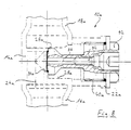
- Fig. 2a is a second embodiment in longitudinal section of a connecting part 10a, wherein the connecting part 10a essentially corresponds to the connecting part 10.
- connection part 10a shown in Fig. 2a can for different Intended use on double or multi-layer panel radiators be attached.
- connection part 10a shows a modified embodiment of the connection part 10a.
- this embodiment points the further channel 28a an undercut 29a in the middle 14a, i.e. the diameter d1 of the channel 28a in the middle piece 14a is larger than the diameter d2 of the Channel 28a in the further connection piece 22a.
- Undercut 29a can have a valve insert in the connecting piece can be used with windows.
- This stepped formation of the further channel 28a is preferred generated by initially in the middle in the production 14a the diameter d1 by machining is manufactured and the further connecting piece 22a only after the completion of the channel section with the diameter d1 is welded to the center piece 14a.
- a seat ring bushing 50 is shown, which is open on one end and on the other Front side converges and in an axially extending Bund 52 passes over.
- a valve seat 54 is formed, which in turn into a valve seat opening formed on collar 52 56 passes.
- Bore 58 extending transversely to the longitudinal direction thereof, the one with on the outer surface of the seat ring bushing 50 trained nose 60 on the opposite side the seat ring bushing 50 is aligned.
- On the seat ring bushing 50 is close to the open face on the lateral surface and on the circumferential surface of the federal government 52 has a receiving groove 62 or 64 for an O-ring 66 or 68.
- connection part 10a shown in FIG. 2a as a valve body To be able to use is first the seat ring bushing 50 into the chamber 30a of the further channel 28a used, with her nose 60 along the im Further connecting piece 22a formed recess 42a guided and held in a defined position.
- the seat ring bush 50 is so far into the further channel 28 introduced until it with its collar 52 in the transition 34a between the first channel 24a and the further channel 28a protrudes, wherein the O-ring 68 provided on the collar 52 the gap seals between the seat ring bushing 50 and the transition 34a, while the other O-ring 66 on the center piece 14a trained entry opening of the further channel 28a and so the central bore of the further connection piece 22a seals against the chamber 30a.
- the seat ring bushing 50 is so through the nose 60 with respect to the further Channel 28a positioned that the bore 58 with the Flow opening of the second channel 26a is aligned.
- valve insert 70 in the Internal thread 40a screwed in the valve insert 70 protrudes into the seat ring bushing 50 with its valve lifter 72.
- the valve lifter 72 is relative to that on the seat ring bushing 50 trained valve seat 54 axially adjustable, that the valve seat opening 56 is completely released, throttled or, if necessary, at least approximately fluid-tight can be locked.
- blind plug 80 shown in FIG. 6 it can also the blind plug 82 shown in FIG. 7 in the further connecting piece 22a are screwed in, filling of the radiator in question without this Connection part 10a must be opened.
- the blind plug 82 has for this purpose one between its face 84 and its external thread 86 radially protruding collar 88, on which a seal 90 is provided.
- Seal 90 With the help of Seal 90 becomes the mouth area of the further channel 28a kept closed in a fluid-tight manner during the blind plug 82 so far from the internal thread 40 of the further connection piece 22a is unscrewed that the opening the opening on the further channel 28a is closed, the transition 34a between the first channel 24a and the other Channel 28a is however slightly released, so that Fluid from the first channel 24a through the chamber 30a into the can flow second channel 26a and vice versa.
- FIG. 8 shows a vent insert 92 Blind plug shown, the same one the other Connection piece 22a of the connection part shown in Fig. 2a 10a can be screwed.
- the ventilation insert 92 corresponds in shape to that shown in FIG. 6 Blind plug 80.
- a vent valve 94 is provided with which when the Transition 34a between the first channel 24a and the further channel 28a, a ventilation channel 96, which in Longitudinal direction of the vent insert 92 through this runs to be opened to vent the radiator can.
- FIG. 9 and 10 is a third embodiment of a connecting part 10b shown as a manifold set can be used for radiators.
- a connecting part 10b shown as a manifold set can be used for radiators.
- the middle channel 14b, the first channel 24b and the further channel 28 drilled so that the first channel 24b only is in flow connection with the further channel 28b.
- the second flow channel 26b was in the middle 14b formed, which in turn with an additional channel 100 is in flow connection, and the connecting piece 16b and 18b drawn in by reshaping.
- the channels 24b, 26b, 28b and 100 was on the plan a surface 20b at which the further channel 28b ends
- Welded pipe section 102 which is closed at one end and has a lateral flow opening 103, at which the further connection piece 22b in turn is welded.
- the further connection piece 22b has an external thread 104 in this exemplary embodiment with which the further connection piece 22b to a heating flow can be connected.
- the further connecting pieces 22b also have an internal thread.
- an additional connection piece 106 on a second of the planar surfaces 20b of the middle piece 14 are welded, whereby the additional connection piece 106 in its shape corresponds to further connecting piece 22b.
- the pipe section 102 on the middle piece 14b was the further connection piece 22b to the additional connecting piece 106 aligned that the two inlet openings of the two Connection pieces 22b and 106 at least approximately in one common level are arranged.
- the modified end part 10b serves as a manifold set for radiator arrangements, with the further Connection piece 22b (see arrow V) of the heating flow is connected so that heating water through the further Connection piece 22b and the pipe section 102 in the connection piece 16b can flow.
- the additional connection piece 106 is connected to the heating return, so that cooled heating water from the radiator through the connecting piece 18b in the additional Connection piece 106 can flow, as indicated by the arrow R is indicated.
- FIGS. 11 and 12 Another embodiment of a connecting part according to the invention 10c is shown in FIGS. 11 and 12.
- an intermediate form 12c a connector 10c manufactured.
- This is fundamental constructed as the connector 10 shown in Fig. 1c and has a center piece 14c and two, coaxial and oppositely aligned connecting pieces 16c and 18c.
- the other, at right angles to Axis of the connecting pieces 16c, 18c aligned third Connection piece 22c is also made in one piece by cold extrusion formed on the center piece 14c.
- This Shaping process can also face the center piece 14c the outer diameters of the tubular connecting pieces 16c and 18c provided with a material reinforcement 15c be so that there is sufficient space for training the Flow channels are present in the center piece 14c.
- the intermediate form 12c can be made in one piece with three molded connection piece 16c, 18c, 22c in the same way with flow channels, as in the previous ones described embodiments.
- a Another alternative way to design the Flow channels can be seen in Figure 12.
- FIGS Figures 13a and 13b Another alternative connector 10d is shown in FIGS Figures 13a and 13b emerge.
- the connector 10d is as an elbow formed, in which essentially two connecting pieces 16d and 22d on a center piece 14d are integrally formed.
- the two connecting pieces 16d and 22d are at right angles to each other.
- In the Center piece 14d can be machined a fault connection between the two at right angles mutually standing connection piece 16d and 22d generated become.
- For combination with other connection elements is also a molding of another connection piece 18d possible.
- FIG. 14a and 14b Another connector 10e according to the invention with three is integrally molded connection piece 16e, 18e, 22e shown in Figures 14a and 14b.
- the connector 10 is in its centerpiece with flow channels for training a distributor connection, such as it is formed is apparent from Figures 9 and 10. In the same way becomes a part for the flow connection on a flat surface 20e welded.
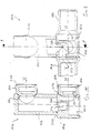
- a radiator arrangement 110 is shown, that of two plate-shaped radiators 112 and 114 is formed, the heater 112 as a heating flow and the radiator 114 serves as a heating return.
- the two radiators 112 and 114 are constructed identically, so that only the radiator 114, which is shown in FIG is shown, is explained.
- the radiator 14 has one upper and a lower transverse channel 116 and 118, wherein cross channels 116 and 118 through a plurality of vertically extending vertical channels 120 in flow communication with each other stand.
- the two radiators 112 and 114 are at each of their corner points connected to each other by a connecting part 10, each connector 10 being integral with its two Connection piece 16 formed on the middle piece 14 and 18 with the upper and lower transverse channels 116 and 118, respectively each radiator 112, 114 are in flow communication. Furthermore, the lower transverse channels 118 are located between them of the two radiators 112 and 114 connecting parts 10 a connecting part designed as a distribution set 10b provided, as shown in Figs. 9 and 10 is.
- the first connection piece 16b is on the radiator 112 serving as heating water flow connected, while the second connecting piece 16 to the serving as heating water return radiator 114 is.
- the connecting part 10b is in the middle between the two connecting parts 10 arranged, i.e. symmetric between the longitudinal edges of the radiators 112 and 114.
- the heating technician can use the for example, the user desires the two below in 16 connecting parts 10 shown by blind plugs lock while the upper connector 10, which is shown in FIG is shown on the right, equipped with the valve insert 70 is and the connector 10 arranged on the left with a Vent insert 92 is provided. Should the heater valve on the left side of the radiator assembly 110 are provided, it is easily possible to use the valve 70 to be exchanged with the ventilation insert.
- each radiator assembly 110 are selected that provides the desired heating output due to its area, without having to place the distribution set in a special position attention to the radiator assembly 10 got to.
- This also simplifies production the radiator arrangement 110, because on the one hand by the individual Adaptation of the connecting parts as a blind piece or as a valve and on the other hand through the central positioning of the connecting part designed as a distribution set 10b one and the same radiator arrangement 110 for the most varied Purposes can be used.
- Flow of the heating water which is shown schematically by Arrows is displayed.
- another flow pattern in the flow channels can be set.
- This can also be used as a distribution set trained connecting part 10b in a corner area be arranged.
- With an appropriate insert vertical channel of the radiator can form a riser, so that with a single-layer radiator, for example, a separate one Riser pipe can be saved.
Landscapes
- Engineering & Computer Science (AREA)
- Physics & Mathematics (AREA)
- Thermal Sciences (AREA)
- Mechanical Engineering (AREA)
- General Engineering & Computer Science (AREA)
- Chemical & Material Sciences (AREA)
- Combustion & Propulsion (AREA)
- Steam Or Hot-Water Central Heating Systems (AREA)
- Cooling Or The Like Of Semiconductors Or Solid State Devices (AREA)
- Lining Or Joining Of Plastics Or The Like (AREA)
- Heating, Cooling, Or Curing Plastics Or The Like In General (AREA)
- Air-Conditioning For Vehicles (AREA)
Applications Claiming Priority (2)
| Application Number | Priority Date | Filing Date | Title |
|---|---|---|---|
| DE20104315U DE20104315U1 (de) | 2001-03-13 | 2001-03-13 | Anschlußteil für einen Heizkörper sowie Heizkörperanordnung |
| DE20104315U | 2001-03-13 |
Publications (3)
| Publication Number | Publication Date |
|---|---|
| EP1249285A2 true EP1249285A2 (fr) | 2002-10-16 |
| EP1249285A3 EP1249285A3 (fr) | 2003-10-01 |
| EP1249285B1 EP1249285B1 (fr) | 2007-01-31 |
Family
ID=7954209
Family Applications (1)
| Application Number | Title | Priority Date | Filing Date |
|---|---|---|---|
| EP02005638A Expired - Lifetime EP1249285B1 (fr) | 2001-03-13 | 2002-03-12 | Procédé de fabrication d'un raccord pour un radiateur de chauffage |
Country Status (3)
| Country | Link |
|---|---|
| EP (1) | EP1249285B1 (fr) |
| AT (1) | ATE353036T1 (fr) |
| DE (2) | DE20104315U1 (fr) |
Cited By (5)
| Publication number | Priority date | Publication date | Assignee | Title |
|---|---|---|---|---|
| DE202009007149U1 (de) | 2009-05-18 | 2010-10-14 | Caradon Heating Europe B.V. | Anschlussteil einer Heizplatte eines Heizkörpers sowie Plattenheizkörper |
| DE202011109189U1 (de) | 2011-12-19 | 2012-02-03 | Wilhelm Schauerte Gmbh & Co. Kg | Anschlußstück mit Elastomermembran-Entlüfter |
| DE202014006323U1 (de) | 2014-08-11 | 2014-09-05 | Wilhelm Schauerte Gmbh & Co. Kg | Anschlußstück mit Elastomermembran-Entlüfter 2 |
| CN105899866A (zh) * | 2014-02-12 | 2016-08-24 | 姜玉洙 | 管道连接件及具备其构件的管道连接预埋盒 |
| EP4600595A1 (fr) * | 2024-02-08 | 2025-08-13 | Commital isi Ekipmanlari Kalip Sanayi Ve Tic. Ltd. Sti | Radiateur |
Families Citing this family (7)
| Publication number | Priority date | Publication date | Assignee | Title |
|---|---|---|---|---|
| DE102007020627B3 (de) * | 2007-04-30 | 2008-10-30 | Hans Berg Gmbh & Co. Kg | Anschlusselement für einen Heizkörper |
| DE102009003198A1 (de) | 2009-05-18 | 2010-11-25 | Caradon Heating Europe B.V. | Verfahren zur Herstellung eines Anschlussteils eines Heizkörpers sowie Anschlussteil eines Heizkörpers |
| DE102010010315B4 (de) | 2010-03-04 | 2026-04-02 | Hans Berg Gmbh & Co. Kg | Ventilanschlussarmatur, Ventiladapterelement, Einsatzelement und Verfahren zum Einpressen eines Einsatzelements |
| DE102010013481B4 (de) | 2010-03-26 | 2016-10-20 | Hans Berg Gmbh & Co. Kg | Abstandshalte- und/oder Verbindungsstück |
| EP2525121B1 (fr) * | 2011-05-19 | 2017-06-14 | Caradon Stelrad B.V. | Élément de garniture de soupape |
| DE102016003022B4 (de) * | 2016-03-12 | 2024-10-10 | Man Truck & Bus Se | Technik zum Verschließen eines Strömungsorgans |
| EP4479688A4 (fr) | 2022-02-16 | 2025-10-22 | Commital Isi Ekipmanlari Kalip Sanayi Ve Tic Ltd Sti | Groupe de raccords sans tuyau en fil-machine pour radiateurs a panneaux dotés de 8 entrées-sorties |
Family Cites Families (4)
| Publication number | Priority date | Publication date | Assignee | Title |
|---|---|---|---|---|
| US2224670A (en) * | 1938-12-15 | 1940-12-10 | William W Criley | Forging die |
| GB1113048A (en) * | 1965-10-08 | 1968-05-08 | Alfred Clay Arbogast | Method and apparatus for making pipe fittings |
| DE3113207C2 (de) * | 1981-04-02 | 1986-01-02 | Harry 6472 Altenstadt König | Verfahren zum Hersstellen eines Anschlußteiles für die Zu- und Ablaufleitung von Plattenheizköpern |
| EP0166796B1 (fr) * | 1984-07-03 | 1989-04-19 | Harry König | Procédé de fabrication de raccords extrudés en forme de T et de L en acier de basse teneur en carbone pour des radiateurs plats |
-
2001
- 2001-03-13 DE DE20104315U patent/DE20104315U1/de not_active Expired - Lifetime
-
2002
- 2002-03-12 DE DE50209400T patent/DE50209400D1/de not_active Expired - Lifetime
- 2002-03-12 EP EP02005638A patent/EP1249285B1/fr not_active Expired - Lifetime
- 2002-03-12 AT AT02005638T patent/ATE353036T1/de not_active IP Right Cessation
Cited By (10)
| Publication number | Priority date | Publication date | Assignee | Title |
|---|---|---|---|---|
| DE202009007149U1 (de) | 2009-05-18 | 2010-10-14 | Caradon Heating Europe B.V. | Anschlussteil einer Heizplatte eines Heizkörpers sowie Plattenheizkörper |
| EP2278235A2 (fr) | 2009-05-18 | 2011-01-26 | Caradon Stelrad B.V. | Elément de liaison d'une plaque chauffante d'un corps de chauffe et corps de chauffe à plaques |
| EP2278235A3 (fr) * | 2009-05-18 | 2011-09-07 | Caradon Stelrad B.V. | Elément de liaison d'une plaque chauffante d'un corps de chauffe et corps de chauffe à plaques |
| DE202011109189U1 (de) | 2011-12-19 | 2012-02-03 | Wilhelm Schauerte Gmbh & Co. Kg | Anschlußstück mit Elastomermembran-Entlüfter |
| EP2607798A2 (fr) | 2011-12-19 | 2013-06-26 | Wilhelm Schauerte GmbH & Co. KG Geschäftsführung | Pièce de raccordement avec désaérateur à membrane élastomère |
| CN105899866A (zh) * | 2014-02-12 | 2016-08-24 | 姜玉洙 | 管道连接件及具备其构件的管道连接预埋盒 |
| US10167984B2 (en) | 2014-02-12 | 2019-01-01 | Ok-su KANG | Pipe connector and pipe-connected embedded box including same |
| DE202014006323U1 (de) | 2014-08-11 | 2014-09-05 | Wilhelm Schauerte Gmbh & Co. Kg | Anschlußstück mit Elastomermembran-Entlüfter 2 |
| EP2988043A1 (fr) | 2014-08-11 | 2016-02-24 | Wilhelm Schauerte GmbH & Co. KG | Pièce de raccordement avec ventilateur à membrane élastomère |
| EP4600595A1 (fr) * | 2024-02-08 | 2025-08-13 | Commital isi Ekipmanlari Kalip Sanayi Ve Tic. Ltd. Sti | Radiateur |
Also Published As
| Publication number | Publication date |
|---|---|
| EP1249285A3 (fr) | 2003-10-01 |
| DE20104315U1 (de) | 2001-05-23 |
| ATE353036T1 (de) | 2007-02-15 |
| EP1249285B1 (fr) | 2007-01-31 |
| DE50209400D1 (de) | 2007-03-22 |
Similar Documents
| Publication | Publication Date | Title |
|---|---|---|
| EP2185306B1 (fr) | Outil de perçage pour machines-outils ainsi que procédé pour sa fabrication | |
| DE102015120962B4 (de) | Kraftstoffverteiler und Verfahren zur Herstellung eines Kraftstoffverteilers | |
| EP1249285B1 (fr) | Procédé de fabrication d'un raccord pour un radiateur de chauffage | |
| DE69510794T2 (de) | Bohrwerkzeug mit ausnehmungen für abgerundete schneideinsätze | |
| EP0583707A1 (fr) | Collier de serrage fileté pour des objets allongés, en particulier pour des tuyaux, cables, tuyaux souples ou analogues | |
| EP1767297B1 (fr) | Foret pour trous profonds, procédé de forage et pièce usiné par moyen d'un tel foret | |
| DE102007020627B3 (de) | Anschlusselement für einen Heizkörper | |
| DE69910994T2 (de) | Schraubverbindung zum schlagbohren, männlicher und weiblicher teil der verbindung und herstellungsverfahren einer solchen verbindung | |
| EP0800907B1 (fr) | Buse à fermeture par aiguille avec moule d'injection et aiguille de fermeture | |
| EP2107284B1 (fr) | Ebauche de boîtier de soupape, kit de soupape et groupe de soupape | |
| DE3611839C2 (fr) | ||
| WO1986003705A1 (fr) | Procede de fabrication d'une boite a clapet en une seule piece pour vanne a tiroir rotatif | |
| DE2738035A1 (de) | Gewindeschneidschraube mit bohrspitze | |
| DE2924321C2 (fr) | ||
| DE10004159C2 (de) | Düsenstock für Gasbrenner | |
| EP0777093A1 (fr) | Méthode pour la manufacture de la robinetterie pour radiateurs | |
| DE19629459C2 (de) | Anbohrarmatur für Kunststoffrohre | |
| DE102009044995A1 (de) | Schneidwerkzeug mit austauschbarem Schneideinsatz | |
| DE1923453C3 (de) | Wasserleitungsventil | |
| DE29614204U1 (de) | Ventilgehäuse | |
| DE102009003198A1 (de) | Verfahren zur Herstellung eines Anschlussteils eines Heizkörpers sowie Anschlussteil eines Heizkörpers | |
| EP0855542B1 (fr) | Procédé pour la fabrication de corps creux et un corps creux | |
| DE19900556C1 (de) | Anschlußvorrichtung zur Herstellung eines Anschlusses an eine Rohrverbindung für fluide Medien | |
| EP0965803B1 (fr) | Connecteur pour un radiateur, en particulièr un radiateur à plaques, d'une installation de chauffage à eau chaude | |
| DE69318284T2 (de) | Verfahren zur Herstellung von Heizkörperelementen für Zentralheizungsanlagen |
Legal Events
| Date | Code | Title | Description |
|---|---|---|---|
| PUAI | Public reference made under article 153(3) epc to a published international application that has entered the european phase |
Free format text: ORIGINAL CODE: 0009012 |
|
| AK | Designated contracting states |
Kind code of ref document: A2 Designated state(s): AT BE CH CY DE DK ES FI FR GB GR IE IT LI LU MC NL PT SE TR |
|
| AX | Request for extension of the european patent |
Free format text: AL;LT;LV;MK;RO;SI |
|
| PUAL | Search report despatched |
Free format text: ORIGINAL CODE: 0009013 |
|
| AK | Designated contracting states |
Kind code of ref document: A3 Designated state(s): AT BE CH CY DE DK ES FI FR GB GR IE IT LI LU MC NL PT SE TR |
|
| AX | Request for extension of the european patent |
Extension state: AL LT LV MK RO SI |
|
| RIC1 | Information provided on ipc code assigned before grant |
Ipc: 7B 21K 1/16 B Ipc: 7F 28F 9/26 B Ipc: 7B 21C 37/29 A |
|
| 17P | Request for examination filed |
Effective date: 20040322 |
|
| AKX | Designation fees paid |
Designated state(s): AT BE CH CY DE DK ES FI FR GB GR IE IT LI LU MC NL PT SE TR |
|
| 17Q | First examination report despatched |
Effective date: 20041105 |
|
| GRAP | Despatch of communication of intention to grant a patent |
Free format text: ORIGINAL CODE: EPIDOSNIGR1 |
|
| RTI1 | Title (correction) |
Free format text: METHOD FOR THE MANUFACTURE OF A FITTING FOR A HEATING RADIATOR |
|
| GRAS | Grant fee paid |
Free format text: ORIGINAL CODE: EPIDOSNIGR3 |
|
| GRAA | (expected) grant |
Free format text: ORIGINAL CODE: 0009210 |
|
| AK | Designated contracting states |
Kind code of ref document: B1 Designated state(s): AT BE CH CY DE DK ES FI FR GB GR IE IT LI LU MC NL PT SE TR |
|
| PG25 | Lapsed in a contracting state [announced via postgrant information from national office to epo] |
Ref country code: NL Free format text: LAPSE BECAUSE OF FAILURE TO SUBMIT A TRANSLATION OF THE DESCRIPTION OR TO PAY THE FEE WITHIN THE PRESCRIBED TIME-LIMIT Effective date: 20070131 Ref country code: DK Free format text: LAPSE BECAUSE OF FAILURE TO SUBMIT A TRANSLATION OF THE DESCRIPTION OR TO PAY THE FEE WITHIN THE PRESCRIBED TIME-LIMIT Effective date: 20070131 Ref country code: IE Free format text: LAPSE BECAUSE OF FAILURE TO SUBMIT A TRANSLATION OF THE DESCRIPTION OR TO PAY THE FEE WITHIN THE PRESCRIBED TIME-LIMIT Effective date: 20070131 Ref country code: FI Free format text: LAPSE BECAUSE OF FAILURE TO SUBMIT A TRANSLATION OF THE DESCRIPTION OR TO PAY THE FEE WITHIN THE PRESCRIBED TIME-LIMIT Effective date: 20070131 |
|
| REG | Reference to a national code |
Ref country code: GB Ref legal event code: FG4D Free format text: NOT ENGLISH |
|
| REG | Reference to a national code |
Ref country code: CH Ref legal event code: EP |
|
| REG | Reference to a national code |
Ref country code: IE Ref legal event code: FG4D Free format text: LANGUAGE OF EP DOCUMENT: GERMAN |
|
| REF | Corresponds to: |
Ref document number: 50209400 Country of ref document: DE Date of ref document: 20070322 Kind code of ref document: P |
|
| PG25 | Lapsed in a contracting state [announced via postgrant information from national office to epo] |
Ref country code: SE Free format text: LAPSE BECAUSE OF FAILURE TO SUBMIT A TRANSLATION OF THE DESCRIPTION OR TO PAY THE FEE WITHIN THE PRESCRIBED TIME-LIMIT Effective date: 20070430 |
|
| PG25 | Lapsed in a contracting state [announced via postgrant information from national office to epo] |
Ref country code: ES Free format text: LAPSE BECAUSE OF FAILURE TO SUBMIT A TRANSLATION OF THE DESCRIPTION OR TO PAY THE FEE WITHIN THE PRESCRIBED TIME-LIMIT Effective date: 20070512 |
|
| PG25 | Lapsed in a contracting state [announced via postgrant information from national office to epo] |
Ref country code: PT Free format text: LAPSE BECAUSE OF FAILURE TO SUBMIT A TRANSLATION OF THE DESCRIPTION OR TO PAY THE FEE WITHIN THE PRESCRIBED TIME-LIMIT Effective date: 20070702 |
|
| NLV1 | Nl: lapsed or annulled due to failure to fulfill the requirements of art. 29p and 29m of the patents act | ||
| GBV | Gb: ep patent (uk) treated as always having been void in accordance with gb section 77(7)/1977 [no translation filed] |
Effective date: 20070131 |
|
| REG | Reference to a national code |
Ref country code: IE Ref legal event code: FD4D |
|
| EN | Fr: translation not filed | ||
| PLBI | Opposition filed |
Free format text: ORIGINAL CODE: 0009260 |
|
| REG | Reference to a national code |
Ref country code: CH Ref legal event code: PL |
|
| PG25 | Lapsed in a contracting state [announced via postgrant information from national office to epo] |
Ref country code: GB Free format text: LAPSE BECAUSE OF FAILURE TO SUBMIT A TRANSLATION OF THE DESCRIPTION OR TO PAY THE FEE WITHIN THE PRESCRIBED TIME-LIMIT Effective date: 20070131 |
|
| PLAX | Notice of opposition and request to file observation + time limit sent |
Free format text: ORIGINAL CODE: EPIDOSNOBS2 |
|
| 26 | Opposition filed |
Opponent name: HANS BERG GMBH & CO. KG Effective date: 20071029 |
|
| BERE | Be: lapsed |
Owner name: KONIG, CHRISTEL Effective date: 20070331 |
|
| PG25 | Lapsed in a contracting state [announced via postgrant information from national office to epo] |
Ref country code: BE Free format text: LAPSE BECAUSE OF NON-PAYMENT OF DUE FEES Effective date: 20070331 |
|
| PG25 | Lapsed in a contracting state [announced via postgrant information from national office to epo] |
Ref country code: MC Free format text: LAPSE BECAUSE OF NON-PAYMENT OF DUE FEES Effective date: 20070331 |
|
| PG25 | Lapsed in a contracting state [announced via postgrant information from national office to epo] |
Ref country code: LI Free format text: LAPSE BECAUSE OF NON-PAYMENT OF DUE FEES Effective date: 20070331 Ref country code: CH Free format text: LAPSE BECAUSE OF NON-PAYMENT OF DUE FEES Effective date: 20070331 |
|
| PLAF | Information modified related to communication of a notice of opposition and request to file observations + time limit |
Free format text: ORIGINAL CODE: EPIDOSCOBS2 |
|
| PG25 | Lapsed in a contracting state [announced via postgrant information from national office to epo] |
Ref country code: IT Free format text: LAPSE BECAUSE OF FAILURE TO SUBMIT A TRANSLATION OF THE DESCRIPTION OR TO PAY THE FEE WITHIN THE PRESCRIBED TIME-LIMIT Effective date: 20070131 Ref country code: FR Free format text: LAPSE BECAUSE OF FAILURE TO SUBMIT A TRANSLATION OF THE DESCRIPTION OR TO PAY THE FEE WITHIN THE PRESCRIBED TIME-LIMIT Effective date: 20070921 Ref country code: GR Free format text: LAPSE BECAUSE OF FAILURE TO SUBMIT A TRANSLATION OF THE DESCRIPTION OR TO PAY THE FEE WITHIN THE PRESCRIBED TIME-LIMIT Effective date: 20070501 |
|
| PLBB | Reply of patent proprietor to notice(s) of opposition received |
Free format text: ORIGINAL CODE: EPIDOSNOBS3 |
|
| PG25 | Lapsed in a contracting state [announced via postgrant information from national office to epo] |
Ref country code: AT Free format text: LAPSE BECAUSE OF NON-PAYMENT OF DUE FEES Effective date: 20070312 |
|
| PG25 | Lapsed in a contracting state [announced via postgrant information from national office to epo] |
Ref country code: FR Free format text: LAPSE BECAUSE OF FAILURE TO SUBMIT A TRANSLATION OF THE DESCRIPTION OR TO PAY THE FEE WITHIN THE PRESCRIBED TIME-LIMIT Effective date: 20070131 |
|
| PG25 | Lapsed in a contracting state [announced via postgrant information from national office to epo] |
Ref country code: CY Free format text: LAPSE BECAUSE OF FAILURE TO SUBMIT A TRANSLATION OF THE DESCRIPTION OR TO PAY THE FEE WITHIN THE PRESCRIBED TIME-LIMIT Effective date: 20070131 |
|
| PG25 | Lapsed in a contracting state [announced via postgrant information from national office to epo] |
Ref country code: LU Free format text: LAPSE BECAUSE OF NON-PAYMENT OF DUE FEES Effective date: 20070312 |
|
| PG25 | Lapsed in a contracting state [announced via postgrant information from national office to epo] |
Ref country code: TR Free format text: LAPSE BECAUSE OF FAILURE TO SUBMIT A TRANSLATION OF THE DESCRIPTION OR TO PAY THE FEE WITHIN THE PRESCRIBED TIME-LIMIT Effective date: 20070131 |
|
| PLBP | Opposition withdrawn |
Free format text: ORIGINAL CODE: 0009264 |
|
| PLBD | Termination of opposition procedure: decision despatched |
Free format text: ORIGINAL CODE: EPIDOSNOPC1 |
|
| PLBM | Termination of opposition procedure: date of legal effect published |
Free format text: ORIGINAL CODE: 0009276 |
|
| STAA | Information on the status of an ep patent application or granted ep patent |
Free format text: STATUS: OPPOSITION PROCEDURE CLOSED |
|
| 27C | Opposition proceedings terminated |
Effective date: 20100926 |
|
| REG | Reference to a national code |
Ref country code: DE Ref legal event code: R082 Ref document number: 50209400 Country of ref document: DE Representative=s name: WUNDERLICH & HEIM PATENTANWAELTE PARTNERSCHAFT, DE |
|
| PGFP | Annual fee paid to national office [announced via postgrant information from national office to epo] |
Ref country code: DE Payment date: 20210325 Year of fee payment: 20 |
|
| REG | Reference to a national code |
Ref country code: DE Ref legal event code: R071 Ref document number: 50209400 Country of ref document: DE |