EP1249568A2 - Ketten- oder Kabelschloss - Google Patents
Ketten- oder Kabelschloss Download PDFInfo
- Publication number
- EP1249568A2 EP1249568A2 EP02006360A EP02006360A EP1249568A2 EP 1249568 A2 EP1249568 A2 EP 1249568A2 EP 02006360 A EP02006360 A EP 02006360A EP 02006360 A EP02006360 A EP 02006360A EP 1249568 A2 EP1249568 A2 EP 1249568A2
- Authority
- EP
- European Patent Office
- Prior art keywords
- cable
- chains
- lock body
- articulated
- lock
- Prior art date
- Legal status (The legal status is an assumption and is not a legal conclusion. Google has not performed a legal analysis and makes no representation as to the accuracy of the status listed.)
- Granted
Links
Images



Classifications
-
- E—FIXED CONSTRUCTIONS
- E05—LOCKS; KEYS; WINDOW OR DOOR FITTINGS; SAFES
- E05B—LOCKS; ACCESSORIES THEREFOR; HANDCUFFS
- E05B67/00—Padlocks; Details thereof
- E05B67/003—Chain, wire or cable locks
Definitions
- the invention relates to a chain, cable or joint lock with one Lock body and an elongated shut-off element in the form of a Chain, a cable or a joint rod, which or which with its first end firmly connected to the lock body and with his second end lockable in the lock body by means of a locking mechanism is.
- An object of the invention is a lock of the aforementioned Kind in such a way that while maintaining a high Security levels a slimmer design of the lock body possible becomes.
- the second end of the shut-off element as an elongated, in is formed in one plane extending end member, which at least one one-sided, preferably a two-sided constriction or undercut, which is in the plane of the end member on at least one of its long sides in the direction of its long axis extends, the at least one constriction or undercut in the locked state of the lock by at least one Bolt element is engaged, the direction of movement in which Level lies in which the end member extends.
- the Direction of movement of the locking element (s) lies in that plane in which is formed as a chain link, cable loop or joint rod end End member extends. This makes it possible that both the end link as well as all parts of the locking mechanism within one flat area can be arranged so that use a slim lock body is possible that is perpendicular in one direction can have minimal dimensions to the plane mentioned.
- the second, lockable in the lock body by means of the locking mechanism The end of the shut-off element can preferably be two symmetrical or have asymmetrical undercuts in the locked state of the castle on two opposite sides of two Bolt elements can be engaged. During the locking process these two locking elements are accordingly in opposite Moves towards each other until they are in the undercuts of engage two opposite sides. This requires a special one secure locking of the end link in the lock body, since the locking done from two sides.
- the two undercuts are formed by a bilateral constriction that extends perpendicular to the longitudinal direction of the end member.
- each side of the constriction then forms one of the two undercuts, in each of which a locking element engages.
- a chain link end link of the type mentioned is produced, for example, by placing it around a suitably shaped, in particular cylindrical spacer, whereupon one or two roller jaws are then moved against the chain link to produce a bilateral constriction from two opposite sides and thereby a deforming one Apply force to the chain link.
- the roller jaws act on areas distant from said spacer, so that the chain link is bent around the spacer by the roller jaws. After completing the deformation, the roller jaws are moved away from the chain link again, causing the chain link to “spring open” again slightly due to unavoidable pretensioning. This widening of the chain link then enables the spacer to be pulled out without problems.
- both locking elements within one Load cell are arranged on which they are directly in the locked state or support indirectly.
- This support complicates that by external Force a bolt in the locked state out of engagement with the Undercut of the end member of the shut-off element are moved can.
- the support of the latch on the power cell can - as mentioned - either directly or indirectly via an additional separate component respectively. Deformation of the bolts due to strikes on the lock body in this case do not affect the locking state, since such Deformations have no effect on the support of the latch on the Have a power cell. Externally applied forces trying to the bolt or bolts in the locked state from their locked position move out, are taken up by the mentioned power cell and rendered ineffective in this way.
- the load cell can be used in particular as drilling protection and / or impact protection have trained walls, through which a protective space for the bolts is at least partially limited.
- the power cell is not only used for this Absorption of forces acting on the bolts, but additionally increases also resistance to other external influences, e.g. Try to interlock the end link and latch Boring to pick up.
- the first locking element can be firmly connected to the power cell, whereas in this case the second locking element is inside the load cell is movable via a locking mechanism.
- the entire Load cell together with the first locking element against one Spring force can be moved in the lock body.
- the first end of the shut-off element which is firmly connected to the lock body, forms a loop which surrounds a connecting pin which connects two regions of the lock body to one another.
- the loop can be realized through the end loop of a cable, through a chain link or through a hole in an articulated rod element.
- the two areas of the lock body connected by means of the connecting pin can be formed in one piece with one another and form an essentially square or U-shaped receptacle for the connecting pin.
- the first end of the shut-off element, which is firmly connected to the lock body is designed as a chain link, as is the second end of the shut-off element which can be locked in the lock body by means of the locking mechanism.
- Said connecting pin which holds the first end of the shut-off element, which is firmly connected to the lock body, can be made of steel with a tensile strength of more than 700 N / mm 2 , and by means of a structure-compressing cold-forming riveting process in corresponding openings of the at least at its two ends be square or U-shaped receptacle.
- both the positive and positive connection with the Recording as well as the "hardening" of the connecting pin achieves what is of course, on the one hand, very economical and, on the other hand, ensures that the non-positive and positive connection between the Recording and the connecting pin through a subsequent hardening process can no longer be affected.
- the connecting pin can consist, for example, of wear-resistant steel, in particular of hard manganese steel, for example X120Mn12 according to DIN.
- the two are connected by means of the connecting pin connected areas of the lock body or the receptacle are integrally formed with one another and essentially as Form a square profile trained receptacle for the connecting pin.
- the two opposite sides of the square profile then have the Openings in which the connecting pin by means of the above Cold deformation riveting is fixed.
- the riveting process must be done in this Case run after that at the first end of the shutoff trained end link was placed around the connecting pin.
- the subsequent connection of connecting pin according to the invention Lock body then ensures that a subsequent loosening of the end member from the connecting pin is not possible.
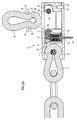
- FIG. 1 shows a three-dimensional exploded drawing of a chain lock, in the assembled state one end of a chain 12 fixed in a lock body 13 and another end of the chain 12 can be locked in the lock body 13 by means of a locking mechanism.
- the chain 12 consists of a number of intertwined, essentially O-shaped chain links, in Fig. 1 for reasons only five chain links are shown for clarity. In a operational version of a chain lock, the chain 12 becomes a higher one Have number of chain links.
- the two end chain links 14 and 15 each have a two-sided Constriction 16, which are each perpendicular to the longitudinal direction the chain links 14, 15 extends.
- the functions of these constrictions 16 are described below in connection with FIGS. 2a to c explained.
- the lock body 13 consists of a housing 17 in the form of a square profile made of hardened steel.
- An opening is in shape in a side end portion of the housing 17 a circular recess 18 is provided which extends through both Side walls of the housing 17 extends through. 2 is only to see one side of the housing 17 and accordingly only one Recess 18.
- the diameter of the recess 18 is dimensioned so that it Diameter of a connecting pin 3 corresponds, which in Fig. 2 in a state after performing the cold forming riveting process according to the invention is shown.
- the connecting pin 3 Before the cold forming riveting process the connecting pin 3 has a constant diameter without an end face Thickenings 8, so that it easily through the recesses 16th can be put through. Only when performing the invention The cold-forming riveting process forms the thickenings 8 from which the connecting pin 3 is fixed in the recesses.
- a receptacle 20 for a locking cylinder which also serves as a longitudinal guide for a force cell 21.
- the load cell 21 is preloaded in the receptacle 20 by means of two spiral springs 22.
- the side walls of the force cell 21 have circular openings 23 which serve to receive a pin 24, which ultimately represents a first locking element.
- An actuating element 25 is arranged in the receptacle 20 adjacent to the locking cylinder and acts on a second locking element 26 in the locked state.
- the receptacle 20 On its underside, the receptacle 20 has one that is not visible in FIG. 1 Blind hole in which a locking pin 27 through an opening of the Housing 17 can be pressed, whereby the locking mechanism in Housing 17 is fixed. Furthermore, the power cell 21 has the End 24 facing away from a support tab bent at a right angle 29th
- FIG. 2a to 2c show sectional views of a lock according to FIG. 1 in unlocked state (Fig. 2a), during the insertion of the chain link 15 in the lock body 13 (Fig. 2b) and in the locked state (Fig. 2c).
- both chain end links 14, 15 have an identical design, which is the manufacture makes the chain more economical and thus advantageous Assembly errors can be avoided.
- Fig. 2a shows that the chain link 14 by means of the invention in Housing 17 fixed connection pin 3 to the housing 17th connected is.
- the receptacle 20 is fixedly and immovably connected to the housing 17 by means of the locking pin 27.
- a locking cylinder 33 is arranged in the receptacle 20 and can be actuated by means of a key 34. The key can be inserted into the locking cylinder 33 through a recess 35 provided in the housing 17 on its underside.
- the locking cylinder 33 is coupled to the actuating element 25 which can be pivoted about the longitudinal axis of the locking cylinder 33 and which is shown in its unlocked position in FIG. 2a.
- Adjacent to the actuating element 25 is the second locking element 26, which is slidably mounted perpendicular to the longitudinal direction of the locking cylinder 33.
- the force cell 21, which is only partially shown for reasons of clarity in FIG. 2a, is placed on the receptacle 20 and is likewise displaceably mounted perpendicular to the longitudinal direction of the locking cylinder 33.
- the pin-shaped first locking element 24 is fixedly connected to the force cell 21.
- the force cell 21 At its end facing away from the first locking element 24, the force cell 21 has a support tab 29 which is bent at right angles and with which it is supported on the actuating element 25 in its locked state (FIG. 2c).
- the housing 17 is provided with an opening 36 on its upper side, through which the chain link 15 can be inserted into the housing 17. Furthermore, the housing 17 has an indentation 37 on its upper side, which on the one hand for additional fixation of the chain link 14 and others to support the locking mechanism inserted into the housing 17 and in particular the support tab 29 is used.
- the force cell 21 is above the spiral springs (only shown in FIG. 1) 22 biased towards the chain link 14, which means that the first locking element 24 is in the insertion path for the chain link 15 located.
- Fig. 2b shows that during the insertion of the chain link 15 this first locking element 24 together counter to the spring force of the coil springs 22 is pushed back with the power cell 21 so that a complete Inserting the chain link 15 into the housing 17 is possible.
- the locking mechanism according to FIG. 2c is then actuated such that the actuating element 25 is rotated by 90 ° by means of the key 34.
- This rotation causes the second locking element 26 to be displaced in the direction of the first locking element 24, so that the two locking elements 24 and 26 come to rest in the constriction 16 of the chain link 15 and thus lock the chain link 15 in the housing 17.
- the first locking element 24 is permanently and non-detachably connected to the load cell 21, which also includes the support plate 29, all forces caused when the chain link 15 is pulled out of the lock body 17 are ultimately absorbed by the load cell 21 and the lock body 17, which is the Security against theft of the castle increased. It is advantageous that the direction of movement of the locking elements 24 and 26 lies in the plane of the drawing (FIG. 2c), the chain link 15 likewise extending in this plane. This makes it possible to make the lock body 14 slim, ie to dimension the lock body 14 so that it has minimal dimensions perpendicular to the plane of the drawing.
Landscapes
- Lock And Its Accessories (AREA)
- Supports For Pipes And Cables (AREA)
- Devices For Conveying Motion By Means Of Endless Flexible Members (AREA)
Abstract
Description
Ein als Kettenglied ausgebildetes Endglied der genannten Art wird beispielsweise dadurch hergestellt, daß es um einen geeignet geformten, insbesondere zylindrischen Abstandshalter gelegt wird, woraufhin dann ein oder zwei Rollbacken zur Erzeugung einer zweiseitigen Einschnürung von zwei gegenüberliegenden Seiten gegen das Kettenglied bewegt werden und dadurch eine verformende Kraft auf das Kettenglied ausüben. Die Rollbacken greifen dabei an von dem genannten Abstandshalter entfernten Bereichen an, so daß durch die Rollbacken das Kettenglied um den Abstandshalter herum gebogen wird. Nach Abschluß der Verformung werden die Rollbacken wieder vom Kettenglied weg bewegt, wodurch aufgrund einer nicht zu vermeidenden Vorspannung das Kettenglied wieder geringfügig "aufspringt". Diese Aufweitung des Kettenglieds ermöglicht dann ein problemloses Herausziehen des Abstandshalters.
Bevorzugt ist, wenn das erste, fest mit dem Schloßkörper verbundene Ende des Absperrelements als Kettenglied ebenso ausgebildet ist, wie das zweite, im Schloßkörper mittels des Schließmechanismus verriegelbare Ende des Absperrelements.
- Fig. 1
- eine dreidimensionale Explosionszeichnung eines erfindungsgemäßen Kettenschlosses, und
- Fig. 2a bis 2c
- Schnittansichten eines montierten Kettenschlosses gemäß Fig. 1, welche den Vorgang des Verriegelns eines Kettenglieds im Schloßkörper veranschaulichen.
Die Seitenwände der Kraftzelle 21 besitzen kreisrunde Öffnungen 23, die zur Aufnahme eines Stiftes 24 dienen, der letztlich ein erstes Riegelelement darstellt.
Benachbart zum Schließzylinder wird in der Aufnahme 20 ein Betätigungselement 25 angeordnet, welches ein zweites Riegelelement 26 im verriegelten Zustand beaufschlagt.
Auf die Aufnahme 20 ist die aus Gründen der Übersichtlichkeit in Fig. 2a nur bereichsweise dargestellte Kraftzelle 21 aufgesetzt, welche ebenfalls senkrecht zur Längsrichtung des Schließzylinders 33 verschiebbar gelagert ist. Fest mit der Kraftzelle 21 verbunden ist das stiftförmig ausgebildete erste Riegelelement 24.
An ihrem dem ersten Riegelelement 24 abgewandten Ende besitzt die Kraftzelle 21 eine rechtwinklig abgeknickte Stützlasche 29, mit der sie sich am Betätigungselement 25 in seinem verriegelten Zustand abstützt (Fig. 2c).
Wenn versucht wird, das Kettenglied im verriegelten Zustand des Schlosses aus dem Schloßkörper 17 herauszuziehen, wirkt zum einen eine Kraft auf den fest mit der Kraftzelle 21 verbundenen Stift 24 und zum anderen eine Kraft über das zweite Riegelelement 26 und das Betätigungselement 25 auf die Stützlasche 29, die einstückig mit der Kraftzelle 21 ausgebildet ist. So wirken letztlich alle Kräfte auf ein und dasselbe Bauteil, nämlich die Kraftzelle 21, was bei entsprechend stabiler Ausbildung der Kraftzelle 21 natürlich vorteilhaft ist, da keine anfälligen Bauteilverbindungen in der Kraftleitungskette vorhanden sind.
Von besonderem Vorteil ist bei der dargestellten Ausführungform die Tatsache, daß das Schloß auch bei einem Abbrechen der Stützlasche 29 im verriegelten Zustand bleiben würde, da sich das Betätigungselement 25 in diesem Fall - ggf. über die abgebrochene Stützlasche 29 - an der Stirnseite 38 der Eindrückung 37 und darüber direkt am Kettenglied 14 abstützen würde.
Vorteilhaft ist, daß die Bewegungsrichtung der Riegelelemente 24 und 26 in der Zeichenebene (Fig. 2c) liegt, wobei sich das Kettenglied 15 ebenfalls in dieser Ebene erstreckt. So wird es möglich, den Schloßkörper 14 schlank auszubilden, d.h. den Schloßkörper 14 so zu bemessen, daß er senkrecht zur Zeichenebene minimale Abmessungen aufweist.
- 3
- Verbindungsstift
- 8
- senkkopfartige Verdickung
- 12
- Kette
- 13
- Schloßkörper
- 14
- Kettenglied
- 15
- Kettenglied
- 16
- Einschnürung
- 17
- Gehäuse
- 18
- Ausnehmung
- 19
- Durchgangsbereich
- 20
- Aufnahme
- 21
- Kraftzelle
- 22
- Spiralfedern
- 23
- Öffnungen
- 24
- Stift (erstes Riegelelement)
- 25
- Betätigungselement
- 26
- zweites Riegelelement
- 27
- Arretierungsstift
- 28
- Öffnung
- 29
- Stützlasche
- 30
- Abstandsbolzen
- 31
- Rollbacken
- 33
- Schließzylinder
- 34
- Schlüssel
- 35
- Ausnehmung
- 36
- Öffnung
- 37
- Eindrückung
- 38
- Stirnseite
Claims (12)
- Ketten, Kabel- oder Gelenkschloß mit einem Schloßkörper (17) und einem langgestreckten Absperrelement in Form einer Kette (12), eines Kabels oder eines Gelenkstabs, welches bzw. welcher mit seinem ersten Ende fest mit dem Schloßkörper (17) verbunden und mit seinem zweiten Ende (15) im Schloßkörper (17) mittels eines Schließmechanismus verriegelbar ist,
dadurch gekennzeichnet, daß das zweite Ende des Absperrelements (12) als längliches, sich im wesentlichen in einer Ebene erstreckendes Endglied (15) ausgebildet ist, welches zumindest eine einseitige, vorzugsweise eine zweiseitige Einschnürung oder Hinterschneidung (16) aufweist, welche sich in der Ebene des Endgliedes (15) an zumindest einer seiner Längsseiten in Richtung dessen Längsachse erstreckt, wobei die zumindest eine Einschnürung oder Hinterschneidung (16) im verriegelten Zustand des Schlosses von zumindest einem Riegelelement (24, 26) hintergriffen wird, dessen Bewegungsrichtung in derjenigen Ebene liegt, in der sich das Endglied (15) erstreckt. - Ketten, Kabel- oder Gelenkschloß nach Anspruch 1,
dadurch gekennzeichnet, daß das zweite, im Schloßkörper (17) mittels des Schließmechanismus verriegelbare Ende des Absperrelements (12) zwei Hinterschneidungen (16) aufweist, die im verriegelten Zustand des Schlosses auf zwei einander gegenüberliegenden Seiten von zwei Riegelelementen (24, 26) hintergriffen werden. - Ketten, Kabel- oder Gelenkschloß nach Anspruch 2,
dadurch gekennzeichnet, daß die zwei Hinterschneidungen durch eine zweiseitige, sich senkrecht zur Längsrichtung des insbesondere als Kettenglied ausgebildeten Endgliedes (15) erstreckende Einschnürung (16) gebildet sind. - Ketten, Kabel- oder Gelenkschloß nach einem der Ansprüche 2 oder 3,
dadurch gekennzeichnet, daß beide Riegelelemente (24, 26) innerhalb einer Kraftzelle (21) angeordnet sind, an der sie sich im verriegelten Zustand direkt oder indirekt abstützen. - Ketten, Kabel- oder Gelenkschloß nach Anspruch 4,
dadurch gekennzeichnet, daß das erste Riegelelement (24) fest mit der Kraftzelle (21) verbunden ist,
das zweite Riegelelement (26) innerhalb der Kraftzelle (21) über einen Schließmechanismus bewegbar ist, und
die Kraftzelle (21) mit dem ersten Riegelelement (24) entgegen einer Federkraft im Schloßkörper (17) beweglich ist. - Ketten, Kabel- oder Gelenkschloß nach einem der vorhergehenden Ansprüche,
dadurch gekennzeichnet, daß das erste, fest mit dem Schloßkörper (17) verbundene Ende des Absperrelements (12) eine Schlaufe (14) bildet, die einen Verbindungsstift (3) umgibt, welcher zwei Bereiche des Schloßkörpers (17) miteinander verbindet. - Ketten, Kabel- oder Gelenkschloß nach Anspruch 6,
dadurch gekennzeichnet, daß die beiden mittels des Verbindungsstifts (3) verbundenen Bereiche des Schloßkörpers (17) einstückig miteinander ausgebildet sind und eine im wesentlichen vierkantförmige oder U-förmige Aufnahme für den Verbindungsstift (3) bilden. - Ketten, Kabel- oder Gelenkschloß nach einem der Ansprüche 6 oder 7,
dadurch gekennzeichnet, daß die Schlaufe durch ein Kettenglied (14), durch eine Schlinge eines Kabels oder durch eine Bohrung in einem Gelenkstab-Element gebildet ist. - Ketten, Kabel- oder Gelenkschloß nach Anspruch 8,
dadurch gekennzeichnet, daß das erste, fest mit dem Schloßkörper (17) verbundene Ende des Absperrelements (12) ebenso ausgebildet ist, wie das zweite, im Schloßkörper (17) mittels des Schließmechanismus verriegelbare Ende des Absperrelements (12). - Ketten, Kabel- oder Gelenkschloß nach einem der Ansprüche 6 bis 9,
dadurch gekennzeichnet, daß der Verbindungsstift (3) aus Stahl mit einer Zugfestigkeit von mehr als 700 N/mm2 besteht, welcher mittels eines zumindest an seinen beiden stirnseitigen Enden erfolgten gefügeverdichtenden Kaltverformungs-Nietvorgangs in den Öffnungen (18, 19) fixiert ist. - Ketten, Kabel- oder Gelenkschloß nach Anspruch 10,
dadurch gekennzeichnet, daß die Zugfestigkeit des Verbindungsstifts (3) größer als 800 N/mm2 ist. - Ketten, Kabel- oder Gelenkschloß nach einem der Ansprüche 10 oder 11,
dadurch gekennzeichnet, daß der Verbindungsstift (3) aus verschleißfestem Stahl, insbesondere aus Hartmanganstahl, vorzugsweise aus X120Mn12 besteht.
Applications Claiming Priority (2)
| Application Number | Priority Date | Filing Date | Title |
|---|---|---|---|
| DE10117927 | 2001-04-10 | ||
| DE2001117927 DE10117927A1 (de) | 2001-04-10 | 2001-04-10 | Ketten, Kabel- oder Gelenkschloß |
Publications (3)
| Publication Number | Publication Date |
|---|---|
| EP1249568A2 true EP1249568A2 (de) | 2002-10-16 |
| EP1249568A3 EP1249568A3 (de) | 2004-01-07 |
| EP1249568B1 EP1249568B1 (de) | 2006-06-07 |
Family
ID=7681123
Family Applications (1)
| Application Number | Title | Priority Date | Filing Date |
|---|---|---|---|
| EP20020006360 Expired - Lifetime EP1249568B1 (de) | 2001-04-10 | 2002-03-21 | Ketten- oder Kabelschloss |
Country Status (2)
| Country | Link |
|---|---|
| EP (1) | EP1249568B1 (de) |
| DE (2) | DE10117927A1 (de) |
Cited By (4)
| Publication number | Priority date | Publication date | Assignee | Title |
|---|---|---|---|---|
| NL1026889C2 (nl) * | 2003-08-26 | 2006-04-25 | Bremicker Soehne Kg A | Beugelslot. |
| DE102011113771A1 (de) * | 2011-09-19 | 2013-03-21 | ABUS August Bremicker Söhne KG | Schlaufenschloss |
| CN110455141A (zh) * | 2019-09-16 | 2019-11-15 | 福建兵工装备有限公司 | 自动夹紧链 |
| CN116490664A (zh) * | 2020-11-26 | 2023-07-25 | Abus·奥古斯特·布莱梅克·索恩有限股份两合公司 | 链条锁和用于链条锁的链条 |
Families Citing this family (1)
| Publication number | Priority date | Publication date | Assignee | Title |
|---|---|---|---|---|
| DE102013210475A1 (de) * | 2013-06-05 | 2014-12-11 | ABUS August Bremicker Söhne KG | Gelenkschloss |
Family Cites Families (7)
| Publication number | Priority date | Publication date | Assignee | Title |
|---|---|---|---|---|
| GB227994A (en) * | 1924-01-09 | 1925-01-29 | John Francis Dimmack | Improvements relating to keyless locks |
| US1921434A (en) * | 1928-05-04 | 1933-08-08 | American Hardware Corp | Spare wheel lock |
| IT8204950U1 (it) * | 1982-06-18 | 1983-12-18 | Viro Innocenti Spa | Lucchetto perfezionato per catene. |
| US5732577A (en) * | 1993-08-11 | 1998-03-31 | Yamaha Hatsudoki Kabushiki Kaisha | Vehicle wheel lock |
| IN188123B (de) * | 1995-04-20 | 2002-08-24 | Vi Goro Sarl | |
| JPH10205192A (ja) * | 1997-01-20 | 1998-08-04 | Osaka Kanagu Kk | 錠前における索条基端部の固定機構 |
| DE19824921B4 (de) * | 1998-06-04 | 2012-01-05 | Trelock Gmbh | Kabelschloss zur Befestigung an Zweirädern |
-
2001
- 2001-04-10 DE DE2001117927 patent/DE10117927A1/de not_active Withdrawn
-
2002
- 2002-03-21 EP EP20020006360 patent/EP1249568B1/de not_active Expired - Lifetime
- 2002-03-21 DE DE50207056T patent/DE50207056D1/de not_active Expired - Lifetime
Cited By (5)
| Publication number | Priority date | Publication date | Assignee | Title |
|---|---|---|---|---|
| NL1026889C2 (nl) * | 2003-08-26 | 2006-04-25 | Bremicker Soehne Kg A | Beugelslot. |
| DE102011113771A1 (de) * | 2011-09-19 | 2013-03-21 | ABUS August Bremicker Söhne KG | Schlaufenschloss |
| CN110455141A (zh) * | 2019-09-16 | 2019-11-15 | 福建兵工装备有限公司 | 自动夹紧链 |
| CN110455141B (zh) * | 2019-09-16 | 2024-04-05 | 福建兵工装备有限公司 | 自动夹紧链 |
| CN116490664A (zh) * | 2020-11-26 | 2023-07-25 | Abus·奥古斯特·布莱梅克·索恩有限股份两合公司 | 链条锁和用于链条锁的链条 |
Also Published As
| Publication number | Publication date |
|---|---|
| EP1249568B1 (de) | 2006-06-07 |
| DE10117927A1 (de) | 2002-10-17 |
| EP1249568A3 (de) | 2004-01-07 |
| DE50207056D1 (de) | 2006-07-20 |
Similar Documents
| Publication | Publication Date | Title |
|---|---|---|
| DE69824071T2 (de) | Lenksäulenverriegelung | |
| EP0369107A2 (de) | Zylinderschloss | |
| DE102010021704B4 (de) | Schlosskappe für ein Gurtschloss | |
| DE4005369C2 (de) | Schließeinrichtung an einer Fahrzeugtür | |
| DE10333211B4 (de) | Schließzylinder | |
| EP1249568A2 (de) | Ketten- oder Kabelschloss | |
| WO2022200421A1 (de) | Betätigungshandhabe | |
| EP2166179A1 (de) | Schließzylinder, insbesondere für ein Türschloss | |
| DE3152281C2 (de) | Schliesseinrichtung f}r die T}r eines Kraftfahrzeuges | |
| DE202019102154U1 (de) | Modulartig aufgebauter Schließzylinder | |
| DE2537572A1 (de) | Fahrzeugtuerscharnier | |
| CH627514A5 (de) | Steuereinrichtung, insbesondere fuer zylinderschloss. | |
| DE102022120478A1 (de) | Betätigungshandhabe | |
| EP0298292B1 (de) | Türschloss mit verschiebbarem Riegel und Falle | |
| EP0167767A2 (de) | Verriegelungsvorrichtung mit wenigstens einem Riegel od. dgl. und mit einer Sperre für diesen Riegel | |
| DE2743091C2 (de) | Vorrichtung zum Vergrößern des Ausschließhubes eines eintourig mittels Schlüssel schließbaren Schubriegels in einem Schloß mit Falle und Schubriegel | |
| DE10015095A1 (de) | Verriegelungsvorrichtung für einen Türflügel | |
| EP1249566B1 (de) | Verfahren zur Herstellung einer Verbindung | |
| EP0683091A1 (de) | Scheibenbremsenschloss | |
| DE10343508A1 (de) | Verdrehsicherung für Transportsicherungsstift einer Spannvorrichtung | |
| DE4211796C2 (de) | Vorrichtung zum Verbinden und Verriegeln zweier Elemente | |
| DE102021201084B4 (de) | Koppeleinrichtung zur kraftübertragenden Verbindung von Bowdenzügen und Bowdenzuganordnung | |
| DE202011005241U1 (de) | Stangenführung | |
| DE8127331U1 (de) | "tuerscharnier mit integriertem tuerhalter" | |
| AT61420B (de) | Zylinderförmiges Einsteckschloß für Möbel aller Art. |
Legal Events
| Date | Code | Title | Description |
|---|---|---|---|
| PUAI | Public reference made under article 153(3) epc to a published international application that has entered the european phase |
Free format text: ORIGINAL CODE: 0009012 |
|
| AK | Designated contracting states |
Kind code of ref document: A2 Designated state(s): AT BE CH CY DE DK ES FI FR GB GR IE IT LI LU MC NL PT SE TR |
|
| AX | Request for extension of the european patent |
Free format text: AL;LT;LV;MK;RO;SI |
|
| PUAL | Search report despatched |
Free format text: ORIGINAL CODE: 0009013 |
|
| AK | Designated contracting states |
Kind code of ref document: A3 Designated state(s): AT BE CH CY DE DK ES FI FR GB GR IE IT LI LU MC NL PT SE TR |
|
| AX | Request for extension of the european patent |
Extension state: AL LT LV MK RO SI |
|
| 17P | Request for examination filed |
Effective date: 20040707 |
|
| AKX | Designation fees paid |
Designated state(s): DE FR GB NL SE |
|
| 17Q | First examination report despatched |
Effective date: 20050120 |
|
| GRAP | Despatch of communication of intention to grant a patent |
Free format text: ORIGINAL CODE: EPIDOSNIGR1 |
|
| GRAS | Grant fee paid |
Free format text: ORIGINAL CODE: EPIDOSNIGR3 |
|
| GRAA | (expected) grant |
Free format text: ORIGINAL CODE: 0009210 |
|
| AK | Designated contracting states |
Kind code of ref document: B1 Designated state(s): DE FR GB NL SE |
|
| PG25 | Lapsed in a contracting state [announced via postgrant information from national office to epo] |
Ref country code: NL Free format text: LAPSE BECAUSE OF FAILURE TO SUBMIT A TRANSLATION OF THE DESCRIPTION OR TO PAY THE FEE WITHIN THE PRESCRIBED TIME-LIMIT Effective date: 20060607 |
|
| REG | Reference to a national code |
Ref country code: GB Ref legal event code: FG4D Free format text: NOT ENGLISH |
|
| REF | Corresponds to: |
Ref document number: 50207056 Country of ref document: DE Date of ref document: 20060720 Kind code of ref document: P |
|
| REG | Reference to a national code |
Ref country code: SE Ref legal event code: TRGR |
|
| GBT | Gb: translation of ep patent filed (gb section 77(6)(a)/1977) |
Effective date: 20060807 |
|
| NLV1 | Nl: lapsed or annulled due to failure to fulfill the requirements of art. 29p and 29m of the patents act | ||
| ET | Fr: translation filed | ||
| PLBE | No opposition filed within time limit |
Free format text: ORIGINAL CODE: 0009261 |
|
| STAA | Information on the status of an ep patent application or granted ep patent |
Free format text: STATUS: NO OPPOSITION FILED WITHIN TIME LIMIT |
|
| 26N | No opposition filed |
Effective date: 20070308 |
|
| REG | Reference to a national code |
Ref country code: FR Ref legal event code: PLFP Year of fee payment: 15 |
|
| REG | Reference to a national code |
Ref country code: FR Ref legal event code: PLFP Year of fee payment: 16 |
|
| REG | Reference to a national code |
Ref country code: FR Ref legal event code: PLFP Year of fee payment: 17 |
|
| PGFP | Annual fee paid to national office [announced via postgrant information from national office to epo] |
Ref country code: FR Payment date: 20190322 Year of fee payment: 18 Ref country code: GB Payment date: 20190320 Year of fee payment: 18 |
|
| PGFP | Annual fee paid to national office [announced via postgrant information from national office to epo] |
Ref country code: SE Payment date: 20190320 Year of fee payment: 18 |
|
| PGFP | Annual fee paid to national office [announced via postgrant information from national office to epo] |
Ref country code: DE Payment date: 20190529 Year of fee payment: 18 |
|
| REG | Reference to a national code |
Ref country code: DE Ref legal event code: R119 Ref document number: 50207056 Country of ref document: DE |
|
| PG25 | Lapsed in a contracting state [announced via postgrant information from national office to epo] |
Ref country code: FR Free format text: LAPSE BECAUSE OF NON-PAYMENT OF DUE FEES Effective date: 20200331 Ref country code: DE Free format text: LAPSE BECAUSE OF NON-PAYMENT OF DUE FEES Effective date: 20201001 Ref country code: SE Free format text: LAPSE BECAUSE OF NON-PAYMENT OF DUE FEES Effective date: 20200322 |
|
| GBPC | Gb: european patent ceased through non-payment of renewal fee |
Effective date: 20200321 |
|
| PG25 | Lapsed in a contracting state [announced via postgrant information from national office to epo] |
Ref country code: GB Free format text: LAPSE BECAUSE OF NON-PAYMENT OF DUE FEES Effective date: 20200321 |