EP1249585A1 - Wärmetauscher einer mehrzylindrigen brennkraftmaschine - Google Patents
Wärmetauscher einer mehrzylindrigen brennkraftmaschine Download PDFInfo
- Publication number
- EP1249585A1 EP1249585A1 EP01901465A EP01901465A EP1249585A1 EP 1249585 A1 EP1249585 A1 EP 1249585A1 EP 01901465 A EP01901465 A EP 01901465A EP 01901465 A EP01901465 A EP 01901465A EP 1249585 A1 EP1249585 A1 EP 1249585A1
- Authority
- EP
- European Patent Office
- Prior art keywords
- heat exchanger
- exhaust
- combustion engine
- internal combustion
- heat exchangers
- Prior art date
- Legal status (The legal status is an assumption and is not a legal conclusion. Google has not performed a legal analysis and makes no representation as to the accuracy of the status listed.)
- Granted
Links
Images








Classifications
-
- F—MECHANICAL ENGINEERING; LIGHTING; HEATING; WEAPONS; BLASTING
- F01—MACHINES OR ENGINES IN GENERAL; ENGINE PLANTS IN GENERAL; STEAM ENGINES
- F01N—GAS-FLOW SILENCERS OR EXHAUST APPARATUS FOR MACHINES OR ENGINES IN GENERAL; GAS-FLOW SILENCERS OR EXHAUST APPARATUS FOR INTERNAL-COMBUSTION ENGINES
- F01N3/00—Exhaust or silencing apparatus having means for purifying, rendering innocuous, or otherwise treating exhaust
- F01N3/08—Exhaust or silencing apparatus having means for purifying, rendering innocuous, or otherwise treating exhaust for rendering innocuous
- F01N3/10—Exhaust or silencing apparatus having means for purifying, rendering innocuous, or otherwise treating exhaust for rendering innocuous by thermal or catalytic conversion of noxious components of exhaust
- F01N3/18—Exhaust or silencing apparatus having means for purifying, rendering innocuous, or otherwise treating exhaust for rendering innocuous by thermal or catalytic conversion of noxious components of exhaust characterised by methods of operation; Control
- F01N3/20—Exhaust or silencing apparatus having means for purifying, rendering innocuous, or otherwise treating exhaust for rendering innocuous by thermal or catalytic conversion of noxious components of exhaust characterised by methods of operation; Control specially adapted for catalytic conversion
- F01N3/2006—Periodically heating or cooling catalytic reactors, e.g. at cold starting or overheating
- F01N3/2046—Periodically cooling catalytic reactors
-
- F—MECHANICAL ENGINEERING; LIGHTING; HEATING; WEAPONS; BLASTING
- F01—MACHINES OR ENGINES IN GENERAL; ENGINE PLANTS IN GENERAL; STEAM ENGINES
- F01N—GAS-FLOW SILENCERS OR EXHAUST APPARATUS FOR MACHINES OR ENGINES IN GENERAL; GAS-FLOW SILENCERS OR EXHAUST APPARATUS FOR INTERNAL-COMBUSTION ENGINES
- F01N3/00—Exhaust or silencing apparatus having means for purifying, rendering innocuous, or otherwise treating exhaust
- F01N3/02—Exhaust or silencing apparatus having means for purifying, rendering innocuous, or otherwise treating exhaust for cooling, or for removing solid constituents of, exhaust
- F01N3/0205—Exhaust or silencing apparatus having means for purifying, rendering innocuous, or otherwise treating exhaust for cooling, or for removing solid constituents of, exhaust using heat exchangers
-
- F—MECHANICAL ENGINEERING; LIGHTING; HEATING; WEAPONS; BLASTING
- F01—MACHINES OR ENGINES IN GENERAL; ENGINE PLANTS IN GENERAL; STEAM ENGINES
- F01N—GAS-FLOW SILENCERS OR EXHAUST APPARATUS FOR MACHINES OR ENGINES IN GENERAL; GAS-FLOW SILENCERS OR EXHAUST APPARATUS FOR INTERNAL-COMBUSTION ENGINES
- F01N3/00—Exhaust or silencing apparatus having means for purifying, rendering innocuous, or otherwise treating exhaust
- F01N3/08—Exhaust or silencing apparatus having means for purifying, rendering innocuous, or otherwise treating exhaust for rendering innocuous
- F01N3/10—Exhaust or silencing apparatus having means for purifying, rendering innocuous, or otherwise treating exhaust for rendering innocuous by thermal or catalytic conversion of noxious components of exhaust
- F01N3/18—Exhaust or silencing apparatus having means for purifying, rendering innocuous, or otherwise treating exhaust for rendering innocuous by thermal or catalytic conversion of noxious components of exhaust characterised by methods of operation; Control
- F01N3/20—Exhaust or silencing apparatus having means for purifying, rendering innocuous, or otherwise treating exhaust for rendering innocuous by thermal or catalytic conversion of noxious components of exhaust characterised by methods of operation; Control specially adapted for catalytic conversion
- F01N3/2006—Periodically heating or cooling catalytic reactors, e.g. at cold starting or overheating
-
- F—MECHANICAL ENGINEERING; LIGHTING; HEATING; WEAPONS; BLASTING
- F01—MACHINES OR ENGINES IN GENERAL; ENGINE PLANTS IN GENERAL; STEAM ENGINES
- F01N—GAS-FLOW SILENCERS OR EXHAUST APPARATUS FOR MACHINES OR ENGINES IN GENERAL; GAS-FLOW SILENCERS OR EXHAUST APPARATUS FOR INTERNAL-COMBUSTION ENGINES
- F01N3/00—Exhaust or silencing apparatus having means for purifying, rendering innocuous, or otherwise treating exhaust
- F01N3/08—Exhaust or silencing apparatus having means for purifying, rendering innocuous, or otherwise treating exhaust for rendering innocuous
- F01N3/10—Exhaust or silencing apparatus having means for purifying, rendering innocuous, or otherwise treating exhaust for rendering innocuous by thermal or catalytic conversion of noxious components of exhaust
- F01N3/24—Exhaust or silencing apparatus having means for purifying, rendering innocuous, or otherwise treating exhaust for rendering innocuous by thermal or catalytic conversion of noxious components of exhaust characterised by constructional aspects of converting apparatus
- F01N3/28—Construction of catalytic reactors
- F01N3/2803—Construction of catalytic reactors characterised by structure, by material or by manufacturing of catalyst support
- F01N3/2807—Metal other than sintered metal
- F01N3/281—Metallic honeycomb monoliths made of stacked or rolled sheets, foils or plates
-
- F—MECHANICAL ENGINEERING; LIGHTING; HEATING; WEAPONS; BLASTING
- F01—MACHINES OR ENGINES IN GENERAL; ENGINE PLANTS IN GENERAL; STEAM ENGINES
- F01N—GAS-FLOW SILENCERS OR EXHAUST APPARATUS FOR MACHINES OR ENGINES IN GENERAL; GAS-FLOW SILENCERS OR EXHAUST APPARATUS FOR INTERNAL-COMBUSTION ENGINES
- F01N3/00—Exhaust or silencing apparatus having means for purifying, rendering innocuous, or otherwise treating exhaust
- F01N3/08—Exhaust or silencing apparatus having means for purifying, rendering innocuous, or otherwise treating exhaust for rendering innocuous
- F01N3/10—Exhaust or silencing apparatus having means for purifying, rendering innocuous, or otherwise treating exhaust for rendering innocuous by thermal or catalytic conversion of noxious components of exhaust
- F01N3/24—Exhaust or silencing apparatus having means for purifying, rendering innocuous, or otherwise treating exhaust for rendering innocuous by thermal or catalytic conversion of noxious components of exhaust characterised by constructional aspects of converting apparatus
- F01N3/28—Construction of catalytic reactors
- F01N3/2882—Catalytic reactors combined or associated with other devices, e.g. exhaust silencers or other exhaust purification devices
- F01N3/2889—Catalytic reactors combined or associated with other devices, e.g. exhaust silencers or other exhaust purification devices with heat exchangers in a single housing
-
- F—MECHANICAL ENGINEERING; LIGHTING; HEATING; WEAPONS; BLASTING
- F01—MACHINES OR ENGINES IN GENERAL; ENGINE PLANTS IN GENERAL; STEAM ENGINES
- F01N—GAS-FLOW SILENCERS OR EXHAUST APPARATUS FOR MACHINES OR ENGINES IN GENERAL; GAS-FLOW SILENCERS OR EXHAUST APPARATUS FOR INTERNAL-COMBUSTION ENGINES
- F01N5/00—Exhaust or silencing apparatus combined or associated with devices profiting by exhaust energy
- F01N5/02—Exhaust or silencing apparatus combined or associated with devices profiting by exhaust energy the devices using heat
-
- F—MECHANICAL ENGINEERING; LIGHTING; HEATING; WEAPONS; BLASTING
- F28—HEAT EXCHANGE IN GENERAL
- F28D—HEAT-EXCHANGE APPARATUS, NOT PROVIDED FOR IN ANOTHER SUBCLASS, IN WHICH THE HEAT-EXCHANGE MEDIA DO NOT COME INTO DIRECT CONTACT
- F28D7/00—Heat-exchange apparatus having stationary tubular conduit assemblies for both heat-exchange media, the media being in contact with different sides of a conduit wall
- F28D7/02—Heat-exchange apparatus having stationary tubular conduit assemblies for both heat-exchange media, the media being in contact with different sides of a conduit wall the conduits being helically coiled
-
- F—MECHANICAL ENGINEERING; LIGHTING; HEATING; WEAPONS; BLASTING
- F28—HEAT EXCHANGE IN GENERAL
- F28D—HEAT-EXCHANGE APPARATUS, NOT PROVIDED FOR IN ANOTHER SUBCLASS, IN WHICH THE HEAT-EXCHANGE MEDIA DO NOT COME INTO DIRECT CONTACT
- F28D7/00—Heat-exchange apparatus having stationary tubular conduit assemblies for both heat-exchange media, the media being in contact with different sides of a conduit wall
- F28D7/08—Heat-exchange apparatus having stationary tubular conduit assemblies for both heat-exchange media, the media being in contact with different sides of a conduit wall the conduits being otherwise bent, e.g. in a serpentine or zig-zag
-
- F—MECHANICAL ENGINEERING; LIGHTING; HEATING; WEAPONS; BLASTING
- F28—HEAT EXCHANGE IN GENERAL
- F28F—DETAILS OF HEAT-EXCHANGE AND HEAT-TRANSFER APPARATUS, OF GENERAL APPLICATION
- F28F21/00—Constructions of heat-exchange apparatus characterised by the selection of particular materials
- F28F21/08—Constructions of heat-exchange apparatus characterised by the selection of particular materials of metal
- F28F21/081—Heat exchange elements made from metals or metal alloys
- F28F21/082—Heat exchange elements made from metals or metal alloys from steel or ferrous alloys
- F28F21/083—Heat exchange elements made from metals or metal alloys from steel or ferrous alloys from stainless steel
-
- F—MECHANICAL ENGINEERING; LIGHTING; HEATING; WEAPONS; BLASTING
- F01—MACHINES OR ENGINES IN GENERAL; ENGINE PLANTS IN GENERAL; STEAM ENGINES
- F01N—GAS-FLOW SILENCERS OR EXHAUST APPARATUS FOR MACHINES OR ENGINES IN GENERAL; GAS-FLOW SILENCERS OR EXHAUST APPARATUS FOR INTERNAL-COMBUSTION ENGINES
- F01N2240/00—Combination or association of two or more different exhaust treating devices, or of at least one such device with an auxiliary device, not covered by indexing codes F01N2230/00 or F01N2250/00, one of the devices being
- F01N2240/02—Combination or association of two or more different exhaust treating devices, or of at least one such device with an auxiliary device, not covered by indexing codes F01N2230/00 or F01N2250/00, one of the devices being a heat exchanger
-
- F—MECHANICAL ENGINEERING; LIGHTING; HEATING; WEAPONS; BLASTING
- F01—MACHINES OR ENGINES IN GENERAL; ENGINE PLANTS IN GENERAL; STEAM ENGINES
- F01P—COOLING OF MACHINES OR ENGINES IN GENERAL; COOLING OF INTERNAL-COMBUSTION ENGINES
- F01P2060/00—Cooling circuits using auxiliaries
- F01P2060/16—Outlet manifold
-
- Y—GENERAL TAGGING OF NEW TECHNOLOGICAL DEVELOPMENTS; GENERAL TAGGING OF CROSS-SECTIONAL TECHNOLOGIES SPANNING OVER SEVERAL SECTIONS OF THE IPC; TECHNICAL SUBJECTS COVERED BY FORMER USPC CROSS-REFERENCE ART COLLECTIONS [XRACs] AND DIGESTS
- Y02—TECHNOLOGIES OR APPLICATIONS FOR MITIGATION OR ADAPTATION AGAINST CLIMATE CHANGE
- Y02T—CLIMATE CHANGE MITIGATION TECHNOLOGIES RELATED TO TRANSPORTATION
- Y02T10/00—Road transport of goods or passengers
- Y02T10/10—Internal combustion engine [ICE] based vehicles
- Y02T10/12—Improving ICE efficiencies
Definitions
- the present invention relates to a heat exchanger for carrying out heat exchange between a heat medium and an exhaust gas from a multicylinder internal combustion engine.
- the present invention has been carried out in view of the above-mentioned circumstances, and it is an object of the present invention to enhance the performance of a heat exchanger that carries out heat exchange between a heat medium and an exhaust gas of a multicylinder internal combustion engine.
- a heat exchanger for a multicylinder internal combustion engine wherein a first heat exchanger is disposed in each exhaust passage extending from a corresponding combustion chamber of a multicylinder internal combustion engine, and a second heat exchanger is disposed in a section where at least two exhaust passages are combined.
- the first heat exchanger is disposed in each exhaust passage extending from the corresponding combustion chamber of the multicylinder internal combustion engine, high temperature exhaust gas can be made to act on the first heat exchanger immediately after coming out of the combustion chamber, thus achieving high heat exchange efficiency, and, moreover, the occurrence of exhaust interference can be avoided, thereby preventing any decrease in the output of the internal combustion engine. Furthermore, since there is little pressure loss in the exhaust gas immediately after coming out of the combustion chamber, enhancement of the heat exchange efficiency due to a heat transfer promoting effect of the pulsed exhaust flow can be expected.
- the second heat exchanger is disposed in the section where at least two exhaust passages are combined, the exhaust gas having no pulsation and a uniform temperature as a result of combining the flows can be made to act on the second heat exchanger, thereby enhancing the heat exchange efficiency.
- the exhaust gas passes through the first heat exchanger and the second heat exchanger sequentially and undergoes effective heat exchange.
- the first heat exchanger and the second heat exchanger are integrated, not only does mounting the heat exchangers on the internal combustion engine and removing them become easy, thereby enhancing the ease of maintenance, but also the integrated structure increases the rigidity of the heat exchangers, thereby enhancing the durability against vibration of the internal combustion engine.
- the second heat exchanger since the second heat exchanger is disposed in a layer around the outer periphery of the first heat exchanger, the second heat exchanger on the outside can suppress outward leakage of the heat of exhaust gas passing through the first heat exchanger, and the heat of the exhaust gas can be recovered without waste.
- a first stage heat exchanger H1 of an embodiment corresponds to the second heat exchanger of the present invention
- second stage to fourth stage heat exchangers H2 to H4 corresponds to the first heat exchanger of the present invention.
- FIGS. 1 to 18 illustrate one embodiment of the present invention
- FIG. 1 is a diagram showing the overall arrangement of a drive system employing the Rankine cycle
- FIG. 2 is a diagram showing the structure of a power transmission system of the drive system
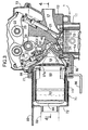
- FIG. 3 is a longitudinal cross section of a cylinder head part of an internal combustion engine
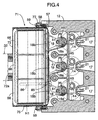
- FIG. 4 is a cross section along line 4-4 in FIG. 3
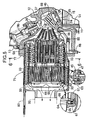
- FIG. 5 is a magnified cross section of an essential part in FIG. 3
- FIG. 6 is a cross section along line 6-6 in FIG. 5
- FIG. 7 is a magnified view of an essential part in FIG. 5
- FIG. 8 is a magnified view of an essential part in FIG. 6
- FIG. 1 is a diagram showing the overall arrangement of a drive system employing the Rankine cycle
- FIG. 2 is a diagram showing the structure of a power transmission system of the drive system
- FIG. 3 is a longitudinal cross section of a cylinder head part of an internal combustion engine
- FIG. 4 is
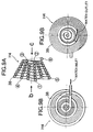
- FIG. 9A is a diagram showing a heat transfer tube of a fourth stage heat exchanger
- FIG. 9B is a view from arrow b in FIG. 9A
- FIG. 9C is a view from arrow c in FIG. 9A
- FIG. 10 is an exploded perspective view of a pre-catalytic system
- FIG. 11 is a schematic diagram showing a water supply route of an evaporator
- FIG. 12 is an exploded perspective view of the evaporator
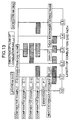
- FIG. 13 is a diagram showing the layout of catalytic systems and heat exchangers in an embodiment and comparative embodiments
- FIG. 14 is a graph showing the relationship between the exhaust gas temperature and the distance from an exhaust port when cold starting;
- FIG. 14 is a graph showing the relationship between the exhaust gas temperature and the distance from an exhaust port when cold starting;
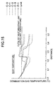
- FIG. 15 is a graph showing the relationship between the exhaust gas temperature and the distance from the exhaust port at high temperature;
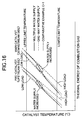
- FIG. 16 is a graph explaining the effect of multiple water supplies;
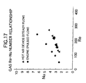
- FIG. 17 is a graph showing the relationship between the Reynolds number and the heat transfer performance for steady flow and pulsed flow; and
- FIG. 18 is a graph showing the relationship between the Reynolds number and the heat transfer performance at different exhaust pressures.
- a waste heat recovery system 2 for an internal combustion engine 1 includes an evaporator 3 that generates vapor having increased temperature and pressure, that is, high-pressure vapor, using, as a heat source, waste heat such as, for example, exhaust gas from the internal combustion engine 1; an expander 4 that generates a shaft output by expansion of the high-pressure vapor; a condenser 5 that liquefies the vapor having decreased temperature and pressure, that is, low-pressure vapor, discharged from the expander 4 after the expansion; and a water supply pump 6 that supplies water from the condenser 5 to the evaporator 3.
- an evaporator 3 that generates vapor having increased temperature and pressure, that is, high-pressure vapor, using, as a heat source, waste heat such as, for example, exhaust gas from the internal combustion engine 1
- an expander 4 that generates a shaft output by expansion of the high-pressure vapor
- a condenser 5 that liquefies the vapor having decreased temperature and pressure, that is, low-pressure
- a power transmission system 121 connected to the waste heat recovery system 2 includes a planetary gear mechanism 122, a belt type continuously variable transmission 123, and an electric generator/motor 124.
- the planetary gear mechanism 122 includes a sun gear 125, a ring gear 126, a planetary carrier 127, and a plurality of planetary gears 128 axially supported by the planetary carrier 127 and meshing simultaneously with the sun gear 125 and the ring gear 126.
- the planetary carrier 127 connected to an output shaft 129 of the expander 4 can engage with a casing, which is not illustrated, via a carrier brake 130.
- the sun gear 125 connected to an input/output shaft 131 of the electric generator/motor 124 can engage with the casing, which is not illustrated, via a sun gear brake 132.
- the ring gear 126 can engage with the casing, which is not illustrated, via a ring gear brake 133.
- Each of the carrier brake 130, the sun gear brake 132, and the ring gear brake 133 is formed from a hydraulic brake or an electromagnetic brake.
- the electric generator/motor 124 is connected to a battery 134 that can be charged and discharged.
- the electric generator/motor 124 charges the battery 134 when it is driven by the shaft output of the expander 4 or the internal combustion engine 1 so as to function as an electric generator, and it assists the drive by the internal combustion engine 1 of driven wheels or starts the internal combustion engine 1 when it functions as a motor powered by the battery 134.
- the belt type continuously variable transmission 123 includes a drive pulley 136 provided on an input shaft 135, a follower pulley 138 provided on an output shaft 137, and an endless belt 139 wrapped around the two pulleys 136, 138.
- the groove width of the drive pulley 136 and the groove width of the follower pulley 138 are individually variable by hydraulic control or electric control; increasing the groove width of the drive pulley 136 and decreasing the groove width of the follower pulley 138 continuously change the gear ratio to the LOW side, and decreasing the groove width of the drive pulley 136 and increasing the groove width of the follower pulley 138 continuously changes the gear ratio to the TOP side.
- a drive gear 140 provided on the ring gear 126 of the planetary gear mechanism 122 meshes with a driven gear 141 provided on the input shaft 135 of the belt type continuously variable transmission 123.
- the shaft output of the internal combustion engine 1 is transmitted to a transmission 143 via an output shaft 142, and the output from the transmission 143 is transmitted to driven wheels, which are not illustrated.
- a drive gear 144 provided on the output shaft 137 of the belt type continuously variable transmission 123 meshes with a driven gear 145 provided on the output shaft 142 of the internal combustion engine 1.
- Torque limiters 146, 147 are provided on the output shaft 129 of the expander 4 and the input/output shaft 131 of the electric generator/motor 124 respectively.
- the torque limiters 146, 147 slip when a torque equal to or greater than a predetermined value is applied to the expander 4 or the electric generator/motor 124, thereby preventing an excess load being generated.
- the torque limiters 146, 147 can be replaced with clutches that disengage when an overload torque that is equal to or greater than a predetermined value is generated.
- a clutch 148 is provided on the output shaft 137 of the belt type continuously variable transmission 123.
- the clutch 148 is for preventing an overload from being applied to the expander 4 due to the driving force transmitted back from the internal combustion engine 1 or the driven wheels, and it provides a connection between the internal combustion engine 1 and the expander 4 when it is engaged, and disconnects the internal combustion engine 1 from the expander 4 when it is disengaged.
- each of the planetary carrier 127 and the ring gear 126 becomes an input element or an output element; a driving force input from the expander 4 into the planetary carrier 127 is output to the ring gear 126 and is then transmitted therefrom to the output shaft 142 of the internal combustion engine 1 via the drive gear 140, the driven gear 141, the belt type continuously variable transmission 123, the drive gear 144, and the driven gear 145, and the shaft output of the expander 4 can thereby assist the shaft output of the internal combustion engine 1.
- a driving force is transmitted via the reverse of the above route when starting the expander 4, the shaft output of the internal combustion engine 1 can smoothly start the expander 4.
- each of the expander 4 or the electric generator/motor 124 becomes an input element and an output element; a driving force input from the expander 4 into the planetary carrier 127 is output to the electric generator/motor 124 via the sun gear 125, thus allowing the electric generator/motor 124 to function as an electric generator, and thereby charging the battery 134.
- a driving force is transmitted via the reverse of the above route when starting the expander 4, the shaft output of the electric generator/motor 124 functioning as a motor can smoothly start the expander 4.
- each of the sun gear 125 and the ring gear 126 becomes an input element or an output element.
- a driving force input into the sun gear 125 from the electric generator/motor 124 functioning as a motor is therefore output from the ring gear 126, is transmitted therefrom to the output shaft 142 of the internal combustion engine 1 via the drive gear 140, the driven gear 141, the belt type continuously variable transmission 123, the drive gear 144, and the driven gear 145, and assists the shaft output of the internal combustion engine 1 or starts the internal combustion engine 1.
- transmitting the shaft output of the internal combustion engine 1 to the electric generator/motor 124 via the reverse of the above route allows the electric generator/motor 124 to function as an electric generator, thereby charging the battery 134.
- the in-line three cylinder internal combustion engine 1 includes a cylinder block 11, a cylinder head 12, and a head cover 13, which are laminated one on another, and pistons 15 are slidably fitted in three cylinder bores 14 formed in the cylinder block 11.
- intake ports 17 and exhaust ports 18 communicating with three corresponding combustion chambers 16 formed in the cylinder head 12 the intake ports 17 are bored within the cylinder head 12 as is conventional, but the exhaust ports 18 are formed from a separate member and joined to the cylinder head 12.
- the upper end of a stem 21 of an intake valve 20 that opens and closes an intake valve hole 19 abuts against one end of an intake rocker arm 23 pivotably supported on an intake rocker arm shaft 22, and the upper end of a stem 26 of an exhaust valve 25 that opens and closes an exhaust valve hole 24 abuts against one end of an exhaust rocker arm 28 pivotably supported on an exhaust rocker arm shaft 27.
- the other end of the intake rocker arm 23 and the other end of the exhaust rocker arm 28 abut against an intake cam 30 and an exhaust cam 31 respectively provided on a camshaft 29 rotating in association with a crankshaft, which is not illustrated, thereby making the intake valve 20 and the exhaust valve 25 open and close.
- the evaporator 3 that generates vapor having increased temperature and pressure, that is, high-pressure vapor, using the exhaust gas of the internal combustion engine 1 as a heat source.
- the evaporator 3 includes an exhaust passage 33 having the three exhaust ports 18 as the base end and extending to an exhaust pipe 32, three pre-catalytic systems 34 and three main catalytic systems 35 disposed within the exhaust passage 33, and heat exchangers H1 to H5 carrying out heat exchange with the exhaust gas flowing in the exhaust passage 33.
- Each of the exhaust ports 18 is formed from a uniform diameter part 18a positioned on the upstream side of the flow of the exhaust gas, and having a substantially constant diameter, and an increasing diameter part 18b provided so as to be connected to the downstream side of the uniform diameter part 18a and having a diameter that increases in a trumpet shape; the fifth stage heat exchanger H5 is provided around the outer periphery of the uniform diameter part 18a, and the fourth stage heat exchanger H4 is provided within the increasing diameter part 18b.
- the fifth stage heat exchanger H5 is formed from about 5 turns of a single heat transfer tube 37 wound around the outer periphery of the uniform diameter part 18a.
- the fourth stage heat exchanger H4 is formed from multiple windings of a single heat transfer tube 38 that is housed within the increasing diameter part 18b, and the heat transfer tube 37 of the fifth stage heat exchanger H5 runs through an opening (not illustrated) formed in the exhaust port 18 and is continuous to the heat transfer tube 38 of the fourth stage heat exchanger H4.
- the heat transfer tube 38 of the fourth stage heat exchanger H4 is wound in a triple coil shape that is tapered so as to follow the shape of the interior of the increasing diameter part 18b of the exhaust port 18; the coil in the inner layer is wound from the rear (the left-hand side in the figure) toward the front (the right-hand side in the figure) while decreasing in diameter and is folded back at the front end; this is followed by the coil in the middle layer, which is wound from the front toward the rear while increasing in diameter and is folded back at the rear end; and this is followed by the coil in the outer layer, which is wound from the rear toward the front while decreasing in diameter.
- FIG. 9B is connected to the third stage heat exchanger H3, which is on the upstream side and will be described later, and a water outlet shown in FIG. 9C is connected to the heat transfer tube 37 of the fifth stage heat exchanger H5, which is on the downstream side.
- the circled numerals 1 ⁇ to 6 ⁇ shown in FIG. 9A show the route via which water flows through the heat transfer tube 38.
- winding the heat transfer tube 38 of the fourth stage heat exchanger H4 in the triple coil shape that is tapered so as to follow the shape of the interior of the increasing diameter part 18b of the exhaust port 18 makes it possible to have a rectifying effect on the exhaust gas that flows through the increasing diameter part 18b, thereby contributing to a reduction in the circulation resistance.
- annular distribution passage forming member 41 is integrally formed on the rear end of the increasing diameter part 18b of the exhaust port 18, and by joining a separate annular distribution passage forming member 42 to the rear face of the distribution passage forming member 41, a third circular distribution passage 43 is formed between the two distribution passage forming members 41, 42.
- the upstream end of the heat transfer tube 38 of the fourth stage heat exchanger H4 is connected to the third circular distribution passage 43.
- the front end of a cylindrical case 44 covering the outer periphery of the pre-catalytic system 34 is joined to the distribution passage forming member 42, and a second circular distribution passage 47 is formed between two annular distribution passage forming members 45, 46, which are superimposed one on another and joined to the rear end of the cylindrical case 44.
- the pre-catalytic system 34 and the third stage heat exchanger H3 are disposed within the cylindrical case 44.
- the pre-catalytic system 34 includes seven sheets of catalyst support 48 formed in honeycomb plates, on the surface of which is supported a known exhaust gas purification catalyst.
- the third stage heat exchanger H3 which is disposed within the cylindrical case 44 so as to surround the seven sheets of catalyst support 48, is formed from two bent heat transfer tubes 49, 49 (see FIG. 10). Each of the heat transfer tubes 49, 49 is bent in a zigzag within a circular plane, then moves to the next plane that is separated therefrom by one pitch in the axial direction and is bent in the same zigzag shape, this being repeated to give a cylindrical outer shape having a plurality of pitches.
- the seven sheets of catalyst support 48 are housed within the internal space formed by interlacing together the two heat transfer tubes 49, 49.
- the two heat transfer tubes 49, 49 are in intimate contact with the surface of the seven sheets of catalyst support 48.
- the upstream ends of the two heat transfer tubes 49, 49 are connected to the second circular distribution passage 47 formed between the distribution passage forming members 45, 46, and the downstream ends thereof are connected to the third circular distribution passage 43 formed between the distribution passage forming members 41, 42.
- the second stage heat exchanger H2 is formed from a large number of heat transfer tubes 52 wound in a coiled shape in one direction and a large number of heat transfer tubes 53 wound in a coiled shape in the other direction, the tubes 52, 53 being disposed alternately so that parts thereof are meshed together, thereby increasing the placement density of the heat transfer tubes 52, 53 within the space.
- the outer periphery of the pre-catalytic system 34 is thus surrounded by the heat transfer tubes 52, 53.
- a first circular distribution passage 56 is formed between a distribution passage forming member 54 fixed to the front end of the cylindrical case 50 on the outer side and a distribution passage forming member 55 joined to the front face of the distribution passage forming member 54.
- the upstream ends of the heat transfer tubes 52, 53 are connected to the first circular distribution passage 56, and the downstream ends of the heat transfer tubes 52, 53 are connected to the second circular distribution passage 47.
- the three pre-catalytic systems 34 are combined into one by a press-formed metal plate mounting plate 57 and fixed to the cylinder head 12.
- Three openings 57a are formed in the mounting plate 57, and the distribution passage forming member 41 of each of the increasing diameter parts 18b of the three exhaust ports 18 is integrally fixed to the corresponding opening 57a.
- An oval-shaped flange 58 fixed to the outer periphery of the mounting plate 57 is fixed to the cylinder head 12 by sixteen bolts 59.
- the three main catalytic systems 35 are disposed to the rear of the three pre-catalytic systems 34.
- the main catalytic systems 35 are formed by supporting a catalyst on the surface of catalyst supports 60 having a honeycomb structure formed in an overall cylindrical shape, and thick ring members 61 are fitted around the outer peripheries thereof.
- the main catalytic systems 35 have a diameter larger than that of the pre-catalytic systems 34, and the main catalytic systems 35 are divided into inner layer parts 35a having the same diameter as that of the pre-catalytic systems 34 and outer layer parts 35b that project outside the outer peripheries of the pre-catalytic systems 34.
- seal members 63 supported on the rear face of the distribution passage forming member 46 via springs 62 resiliently abut against the front faces of the main catalytic systems 35.
- End caps 65 are supported, via springs 64, on the rear ends of the ring members 61 on the outer peripheries of the main catalytic systems 35.
- the rear faces of the three end caps 65 abut against projections 66a provided on the front face of an inner wall member 66, which will be described later, and are pushed forward.
- the outsides of the three pre-catalytic systems 34 and the three main catalytic systems 35 are covered with a detachable common cover 71.
- the cover 71 includes a plate-shaped distribution passage forming member 72 having a mounting hole 72a for the exhaust pipe 32 in its center and a triple ring-shaped distribution passage forming member 73 joined to the front face of the distribution passage forming member 72, and a first triple ring-shaped distribution passage 74 is formed between the two distribution passage forming members 72, 73.
- a tubular member 75 positioned radially outside and a tubular member 76 positioned radially inside extend forward, with a slight gap therebetween, from the triple ring-shaped distribution passage forming member 73, and an oval flange 77 provided on the front end of the outer tubular member 75 is superimposed on the flange 58 and they are tightened together by the bolts 59.
- a triple ring-shaped distribution passage forming member 78 is fixed to the front end of the inner tubular member 76, and a second triple ring-shaped distribution passage 80 is formed by joining, to the front face of the distribution passage forming member 78, a distribution passage forming member 79 of the substantially same shape.
- the first triple ring-shaped distribution passage 74 and the second triple ring-shaped distribution passage 80 have an identical shape and face each other in the front to rear direction.
- the cup-shaped inner wall member 66 is housed within the cover 71, and the first stage heat exchanger H1 is disposed between the outer periphery of the inner wall member 66 and the inner periphery of the inner tubular member 76.
- the first stage heat exchanger H1 has a similar structure to that of the second stage heat exchangers H2; a large number of heat transfer tubes 81 wound in a coiled shape in one direction and a large number of heat transfer tubes 82 wound in a coiled shape in the other direction are disposed alternately so that parts thereof are meshed together, and these heat transfer tubes 81, 82 surround the outer peripheries of the second stage heat exchangers H2 and the outer peripheries of the main catalytic systems 35.
- the upstream ends of the heat transfer tubes 81, 82 are connected to the first triple ring-shaped distribution passage 74, and the downstream ends thereof are connected to the second triple ring-shaped distribution passage 80.
- the materials for the heat transfer tubes 37 of the fifth stage heat exchangers H5, the heat transfer tubes 38 of the fourth stage heat exchangers H4, the heat transfer tubes 49 of the third stage heat exchangers H3, the heat transfer tubes 52, 53 of the second stage heat exchangers H2, and the heat transfer tubes 81, 82 of the first stage heat exchanger H1 are preferably heat-resistant stainless steel (austenite type such as SUS 316L or SUS 310S, ferrite type such as SUS 430 or SUS 444) or a nickel-based heat-resistant alloy. Joining of the heat transfer tubes is preferably carried out by brazing or mechanical restraint.
- heat-resistant stainless steel e.g., 20 % by weight Cr - 5 % by weight Al ferrite type stainless steel
- a nickel-based heat-resistant alloy foil thickness 0.1 mm or below
- cordylite is preferable.
- a water inlet 83 into which water that is a source of high pressure vapor is supplied, is provided in a central part of the first triple ring-shaped distribution passage 74, which communicates with the second triple ring-shaped distribution passage 80 via a large number of the heat transfer tubes 81, 82 of the first stage heat exchanger H1 disposed so as to surround the outer peripheries of the three main catalytic systems 35, and the second triple ring-shaped distribution passage 80 communicates with the three first circular distribution passages 56 via two detachable couplings 84.
- the three first circular distribution passages 56 communicate with the three second circular distribution passages 47 via the heat transfer tubes 52, 53 of the second stage heat exchangers H2 disposed so as to surround the outer peripheries of the three pre-catalytic systems 34, and each of these three second circular distribution passages 47 communicates with the corresponding one of the three third circular distribution passages 43 via two of the heat transfer tubes 49 of the third stage heat exchangers H3 disposed within the three pre-catalytic systems 34.
- Each of the three third circular distribution passages 43 continues through one of the heat transfer tubes 38 of the fourth stage heat exchangers H4 that pass through the interiors of the three exhaust ports 18 and one of the heat transfer tubes 37 of the fifth stage heat exchangers H5 that pass around the exteriors of the three exhaust ports 18, and they are then combined together by a coupling 85 and supplied to the expander 4 in a subsequent stage from a water outlet 86.
- the exhaust gas coming out of the internal combustion engine 1 exchanges heat with the fifth stage heat exchangers H5 formed from the heat transfer tubes 37 wound around the outer peripheries of the uniform diameter parts 18a.
- the exhaust gas that has flowed from the uniform diameter parts 18a of the exhaust ports 18 into the increasing diameter parts 18b exchanges heat by direct contact with the fourth stage heat exchangers H4 formed from the heat transfer tubes 38 wound in a triple coil shape and housed within the increasing diameter parts 18b.
- the exhaust gas passes from the exhaust ports 18 through the interior of the seven catalyst supports 48 of each of the three pre-catalytic systems 34 to purify its harmful components and, at this point, exchanges heat with the third stage heat exchangers H3 formed from the heat transfer tubes 49 surrounding the peripheries of the catalyst supports 48.
- the exhaust gas that has passed through the three pre-catalytic systems 34 passes through the inner layer parts 35a of the three main catalytic systems 35 from the front to the rear, is then blocked by the end caps 65 and makes a U-turn, and passes through the outer layer parts 35b of the main catalytic systems 35 from the rear to the front; during this stage, harmful components in the exhaust gas are purified by the main catalytic systems 35.
- the exhaust gas coming out of the main catalytic systems 35 exchanges heat while flowing, from the rear to the front, through the second stage heat exchangers H2 formed from the heat transfer tubes 52, 53 disposed between the pairs of cylindrical cases 50, 51, then changes direction through 180°, exchanges heat while flowing, from the front to the rear, through the first stage heat exchanger H1 formed from the heat transfer tubes 81, 82 disposed between the tubular member 76 and the inner wall member 66, and is finally discharged into the exhaust pipe 32 through the mounting hole 72a of the distribution passage forming member 72.
- the three main catalytic systems 35 are brought up to the three pre-catalytic systems 34 from the rear, and the outer peripheries at the front end of the ring members 61 on the outer peripheries of the main catalytic systems 35 are fitted to the outer peripheries at the rear end of the cylindrical cases 50 of the second stage heat exchangers H2.
- the seal members 63 supported on the rear faces of the distribution passage forming members 46 via the springs 62 resiliently abut against the front faces of the main catalytic systems 35 (see FIG. 4).
- the cover 71 is moved forward so as to cover the outer peripheries of the three main catalytic systems 35 and the three second stage heat exchangers H2 with the triple ring-shaped first stage heat exchanger H1 in which three circles are staggered in the lateral direction and superimposed one on another, and the flange 77 provided on the tubular member 75 of the cover 71 is superimposed on the rear face of the flange 58 of the mounting plate 57 and joined to the cylinder head 12 by the sixteen bolts 59.
- the projections 66a of the inner wall member 66 within the cover 71 push the end caps 65 of the main catalytic systems 35 forward so as to compress the springs 64 between spring seats 67 provided on the outer peripheries of the end caps 65 and spring seats 68 provided on the rear ends of the ring members 61 on the outer peripheries of the main catalytic systems 35 (see FIG. 4).
- the assembly is carried out so as to give a slight gap in the radial direction between an inner layer part including the pre-catalytic systems 34 and the main catalytic systems 35, and the cover 71, which is an outer layer part covering the outer peripheries thereof, thermal expansion thereof in the radial direction can be absorbed.
- the main catalytic systems 35 are resiliently retained by the springs 62 and 64 between the rear faces of the pre-catalytic systems 34 and the front face of the inner wall member 66 of the cover 71, thermal expansion of the pre-catalytic systems 34 and the main catalytic systems 35 in the axial direction can be absorbed.
- the three first circular distribution passages 56 are each connected to the second triple ring-shaped distribution passage 80 at the front end of the cover 71 via the couplings 84, and the three heat transfer tubes 37 of the fifth stage heat exchangers H5 extending from the three exhaust ports 18 are combined by the coupling 85 to thereby complete the assembly of the evaporator 3.
- a catalytic system for purifying an exhaust gas is divided into the pre-catalytic systems 34 on the upstream side and the main catalytic systems 35 on the downstream side, the fourth stage heat exchangers H4 and the fifth stage heat exchangers H5 are disposed on the upstream side of the flow of the exhaust gas, of the pre-catalytic systems 34, and the first stage heat exchanger H1 and the second stage heat exchangers H2 are disposed on the downstream side of the flow of the exhaust gas, of the main catalytic systems 35.
- the third stage heat exchangers H3 are housed within the pre-catalytic systems 34.
- Comparative Example C-0 includes neither a catalytic system nor a heat exchanger
- Comparative Example C-1 includes only a main catalytic system
- Comparative Example C-2 includes a main catalytic system as the stage following a pre-catalytic system
- Comparative Example C-3 includes heat exchangers as both the stage prior to and the stage following a main catalytic system.
- FIG. 14 shows the change in temperature of the exhaust gas from the upstream side to the downstream side (L0 ⁇ L1 ⁇ L2 ⁇ L3 ⁇ L4 ⁇ L5) during a cool period immediately after starting the internal combustion engine 1.
- the pre-catalytic systems 34 are disposed on the upstream side of the exhaust passage 33 and the capacity of the pre-catalytic systems 34 is set small, the temperature of the pre-catalytic systems 34 can be increased quickly to the catalyst activation temperature or above even during the cool period, thereby reducing the harmful components in the exhaust gas effectively.
- the exhaust gas in the inner layer parts 35a is covered by the exhaust gas in the outer layer parts 35b, thus preventing thermal leakage and thereby preventing any degradation in the heat exchange efficiency.
- FIG. 15 shows the change in temperature of the exhaust gas from the upstream side to the downstream side when the internal combustion engine 1 is being operated at high temperature.
- the pre-catalytic systems 34 are positioned close to the exhaust ports 18, since the fourth stage heat exchangers H4 and the fifth stage heat exchangers H5 are placed in the exhaust ports 18, it is possible to prevent the catalyst temperature of the pre-catalytic systems 34 from exceeding the heat resistant temperature.
- the catalyst supports 48 of the third stage heat exchangers H3 are divided into seven narrow pieces, and the zigzag-bent heat transfer tubes 49 of the third stage heat exchangers H3 are in direct contact with the peripheries of the catalyst supports 48, the catalyst temperature of the pre-catalytic systems 34 can more reliably be prevented from exceeding the heat resistant temperature.
- first stage heat exchanger H1, the second stage heat exchangers H2, the third stage heat exchangers H3, the fourth stage heat exchangers H4, and the fifth stage heat exchangers H5 are connected in line, and water is supplied sequentially from the first stage heat exchanger H1 side to the fifth stage heat exchangers H5 side (this water supply method is called one-way water supply), increasing/decreasing the amount of water supplied can appropriately control the temperatures of the pre-catalytic systems 34 and the main catalytic systems 35 according to the operational state of the internal combustion engine 1 (see Table 1).
- the overall exhaust gas purification performance and durability of the catalytic system can be enhanced.
- integral provision of the third stage heat exchangers H3 within the pre-catalytic systems 34 can actively control the temperature of the pre-catalytic systems 34, and midstream water supply to the first circular distribution passages 56, the second circular distribution passages 47, and the third circular distribution passages 43 in the vicinity of the pre-catalytic systems 34 can not only control the temperature of the pre-catalytic systems 34 themselves but can also appropriately control the temperature of the main catalytic systems 35 positioned downstream thereof, thereby greatly enhancing the overall exhaust gas purification performance.
- heat transfer surface densities heat transfer area/volume of the five heat exchangers H1 to H5
- that of the first stage heat exchanger H1 is the highest, and the surface density gradually decreases therefrom toward the fifth stage heat exchangers H5.
- the passage cross sectional areas of the five heat exchangers H1 to H5 that of the first stage heat exchanger H1 is the smallest, and the cross sectional area gradually increases therefrom toward the fifth stage heat exchangers H5.
- the heat transfer surface densities and the passage cross sectional areas of the first stage to fourth stage heat exchangers H1 to H4 are shown in Table 3.
- the second stage to fifth stage heat exchangers H2 to H5 which are heat exchangers in the earlier stage as seen from the internal combustion engine 1, are provided for each one of the exhaust ports 18, and since the exhaust gases coming from the exhaust ports 18 are not mixed, it is possible to avoid the occurrence of exhaust interference, thereby preventing any decrease in the output of the internal combustion engine 1. Furthermore, since there are pressure pulsations in the exhaust gas at the exits of the exhaust ports 18, and the exhaust pressure is high, a heat transfer promoting effect can be expected.
- FIG. 17 shows a comparison of the heat transfer performance at several Reynolds numbers between a hot air device without exhaust pulsations and an internal combustion engine with exhaust pulsations, and it confirms that the internal combustion engine with exhaust pulsations has the higher heat transfer performance.
- FIG. 18 shows a comparison of the heat transfer performance at several Reynolds numbers at two different exhaust pressures in a single cylinder internal combustion engine provided with a grouped pipe type heat exchanger, and it confirms that the higher the exhaust pressure, the higher the heat transfer performance.
- the exhaust gas can be maintained at a constant high temperature and, unlike pulsed flow, the exhaust gas can be made to have a steady flow that does not stop, thereby preventing any deterioration in the heat exchange performance.
- the exhaust gas flows from the internal combustion engine 1 side to the exhaust pipe 32 side
- water flows from the exhaust pipe 32 side to the internal combustion engine 1 side
- the exhaust gas and the water are in a cross-flow state, and the difference in temperature between the exhaust gas and the water can therefore be maximized across all of the first stage to fifth stage heat exchangers H1 to H5, thereby contributing to an enhancement of the heat exchange efficiency between the exhaust gas and the water.
- the width of the evaporator 3 (width of the internal combustion engine 1 in the direction of the crankshaft) differs little from the width of the three cylinder bores 14, and it is extremely compact. Moreover, not only can the evaporator 3 be detached from the cylinder head 12 by merely loosening the sixteen bolts 59, thus providing ease of maintenance, but also the entire evaporator 3 is integrated with high rigidity by the cover 71, thereby enhancing the durability against vibration of the internal combustion engine 1.
- the exhaust passage 33 is bent into a three stage zigzag shape and the first stage to fourth stage heat exchangers H1 to H4 are disposed in layers in the radial direction, the overall dimensions of the evaporator 3 can be reduced as much as possible while minimizing thermal leakage and preventing noise from being dissipated from the interior of the evaporator 3, thereby providing a compact layout thereof in the cylinder head 12 of the internal combustion engine E.
- first stage to fifth stage heat exchangers H1 to H5 are arranged in a labyrinth form by disposing the pre-catalytic systems 34 and the main catalytic systems 35 in layers in the radial direction, not only can their silencing effect be effective in preventing exhaust noise from leaking outside the waste heat recovery system 2, but also an exhaust gas temperature lowering effect can be given, mainly by the first stage to fifth stage heat exchangers H1 to H5. This allows an exhaust muffler to be simplified or omitted, thereby making the exhaust system itself compact and lightweight.
- the degrees of freedom in designing with regard to heat resistance increase, and the use of a material such as a plastic for the exhaust passage becomes possible.
- the degrees of freedom in the shape of the exhaust passage, the degrees of freedom in mounting on a vehicle, the degrees of freedom in terms of cooling characteristics, etc. increase, and the degrees of freedom in the design of the entire vehicle, which has been subjected to restrictions by conventional exhaust systems, can be increased, thereby contributing to a reduction in the overall weight of the exhaust system.
- the first heat exchanger is formed from three heat exchangers, which are the second stage heat exchanger H2, the third stage heat exchanger H3, and the fourth stage heat exchanger H4, but the number of heat exchangers from which it is formed can be a number other than three.
- the second heat exchanger is formed from the first stage heat exchanger H1 alone, but the number of heat exchanges from which it is formed can be a number other than two.
- a three-cylinder internal combustion engine 1 is illustrated, but the present invention can also be applied to a multicylinder internal combustion engine having a number of cylinders other than three.
- the heat exchanger of a multicylinder internal combustion engine related to the present invention can be applied suitably to an internal combustion engine for an automobile, but it can also be applied to an internal combustion engine for any non-automobile application.
Landscapes
- Engineering & Computer Science (AREA)
- Chemical & Material Sciences (AREA)
- Chemical Kinetics & Catalysis (AREA)
- Mechanical Engineering (AREA)
- General Engineering & Computer Science (AREA)
- Combustion & Propulsion (AREA)
- Health & Medical Sciences (AREA)
- Toxicology (AREA)
- Physics & Mathematics (AREA)
- Thermal Sciences (AREA)
- Exhaust Gas After Treatment (AREA)
- Heat-Exchange Devices With Radiators And Conduit Assemblies (AREA)
Applications Claiming Priority (3)
| Application Number | Priority Date | Filing Date | Title |
|---|---|---|---|
| JP2000017783 | 2000-01-21 | ||
| JP2000017783A JP4229559B2 (ja) | 2000-01-21 | 2000-01-21 | 多気筒内燃機関の熱交換装置 |
| PCT/JP2001/000348 WO2001053670A1 (en) | 2000-01-21 | 2001-01-19 | Heat exchangers of multiple cylinder internal combustion engine |
Publications (3)
| Publication Number | Publication Date |
|---|---|
| EP1249585A1 true EP1249585A1 (de) | 2002-10-16 |
| EP1249585A4 EP1249585A4 (de) | 2004-06-16 |
| EP1249585B1 EP1249585B1 (de) | 2005-08-31 |
Family
ID=18544732
Family Applications (1)
| Application Number | Title | Priority Date | Filing Date |
|---|---|---|---|
| EP01901465A Expired - Lifetime EP1249585B1 (de) | 2000-01-21 | 2001-01-19 | Wärmetauscher einer mehrzylindrigen brennkraftmaschine |
Country Status (5)
| Country | Link |
|---|---|
| US (1) | US7055315B2 (de) |
| EP (1) | EP1249585B1 (de) |
| JP (1) | JP4229559B2 (de) |
| DE (1) | DE60113063T2 (de) |
| WO (1) | WO2001053670A1 (de) |
Cited By (11)
| Publication number | Priority date | Publication date | Assignee | Title |
|---|---|---|---|---|
| US6823668B2 (en) * | 2000-09-25 | 2004-11-30 | Honda Giken Kogyo Kabushiki Kaisha | Waste heat recovery device of internal combustion engine |
| EP1326017A4 (de) * | 2000-10-10 | 2006-05-24 | Honda Motor Co Ltd | Hybridfahrzeug |
| EP2110527A2 (de) | 2008-04-14 | 2009-10-21 | MAN Nutzfahrzeuge Österreich AG | Nutzfahrzeug mit einem Verbrennungsmotor und einem dessen Wärmequellen ausnutzenden Wärmerückgewinnungssystem |
| WO2010076588A1 (en) * | 2008-12-30 | 2010-07-08 | Renault Trucks | Energy recovery system for an internal combustion engine |
| EP2312136A1 (de) * | 2009-10-15 | 2011-04-20 | Kabushiki Kaisha Toyota Jidoshokki | Abwärmenutzungssystem |
| DE102012004600A1 (de) | 2012-03-07 | 2013-09-12 | Daimler Ag | Abwärmenutzungsvorrichtung für ein Kraftfahrzeug |
| WO2012069177A3 (de) * | 2010-11-22 | 2014-04-03 | Conpower Patente Gmbh & Co Kg | Verfahren zum betrieb einer kreisprozessanlage, sowie kreisprozessanlage selbst |
| DE102013019364A1 (de) | 2013-11-19 | 2014-07-31 | Daimler Ag | Abwärmenutzungseinrichtung für eine Verbrennungskraftmaschine |
| DE102014018955A1 (de) | 2014-12-18 | 2016-06-23 | Daimler Ag | Kraftfahrzeug und Verfahren zu dessen Betrieb |
| DE102016218462A1 (de) | 2016-09-26 | 2018-03-29 | Mtu Friedrichshafen Gmbh | Anordnung mit einem System zur Durchführung eines thermodynamischen Kreisprozesses und einer Brennkraftmaschine, sowie Verfahren zum Betreiben einer solchen Anordnung |
| CN108240775A (zh) * | 2016-12-26 | 2018-07-03 | 本田技研工业株式会社 | 热交换器 |
Families Citing this family (19)
| Publication number | Priority date | Publication date | Assignee | Title |
|---|---|---|---|---|
| JP3730903B2 (ja) | 2001-11-21 | 2006-01-05 | 本田技研工業株式会社 | 熱交換器 |
| JP3730904B2 (ja) | 2001-11-21 | 2006-01-05 | 本田技研工業株式会社 | 熱交換装置 |
| DE102005051428B4 (de) * | 2004-10-29 | 2015-05-28 | Denso Corporation | Abwärmenutzungsvorrichtung |
| JP4706536B2 (ja) * | 2006-03-30 | 2011-06-22 | トヨタ自動車株式会社 | 排熱回収装置 |
| DE112007000046B4 (de) | 2006-06-08 | 2012-03-29 | Denso Corporation | Abgaswärmerückgewinnungsvorrichtung |
| US7797938B2 (en) * | 2007-07-31 | 2010-09-21 | Caterpillar Inc | Energy recovery system |
| DE102007060523A1 (de) * | 2007-12-13 | 2009-06-18 | Behr Gmbh & Co. Kg | Abgasanlage mit einem Abgasverdampfer, Verfahren zum Betreiben einer Brennkraftmaschine eines Kraftfahrzeuges |
| US20100006073A1 (en) * | 2008-07-10 | 2010-01-14 | Jayant Jatkar | Increasing effeciency of internal combustion engines to increase mileage of vehicles |
| JP5486858B2 (ja) * | 2009-07-07 | 2014-05-07 | 日本発條株式会社 | 熱交換器 |
| DE102009035522B4 (de) | 2009-07-31 | 2013-09-19 | Iav Gmbh Ingenieurgesellschaft Auto Und Verkehr | Verfahren und Vorrichtung zur verbesserten Energieausnutzung der Wärmeenergie von Brennkraftmaschinen |
| JP2011185151A (ja) * | 2010-03-08 | 2011-09-22 | National Maritime Research Institute | 排熱回収サイレンサー及び排熱回収サイレンサーシステム |
| JP2012183978A (ja) * | 2011-03-08 | 2012-09-27 | Denso Corp | 暖房装置 |
| JP2012246872A (ja) * | 2011-05-30 | 2012-12-13 | Toyota Industries Corp | 廃熱回収機器及び廃熱回収装置 |
| DE102012216453A1 (de) * | 2012-09-14 | 2014-03-20 | Eberspächer Exhaust Technology GmbH & Co. KG | Wärmeübertrager |
| DE102012216448A1 (de) * | 2012-09-14 | 2014-03-20 | Eberspächer Exhaust Technology GmbH & Co. KG | Wärmeübertrager |
| DE102012220893A1 (de) * | 2012-11-15 | 2014-05-15 | Zf Friedrichshafen Ag | Fahrzeugantrieb mit einem Verbrennungsmotor und einer Abwärmenutzungseinheit |
| JP6632198B2 (ja) * | 2015-02-05 | 2020-01-22 | 三菱日立パワーシステムズ株式会社 | 熱交換器及び熱交換器の制御方法 |
| US10428713B2 (en) | 2017-09-07 | 2019-10-01 | Denso International America, Inc. | Systems and methods for exhaust heat recovery and heat storage |
| WO2019168927A1 (en) * | 2018-03-01 | 2019-09-06 | Cummins Inc. | Waste heat recovery hybrid power drive |
Family Cites Families (14)
| Publication number | Priority date | Publication date | Assignee | Title |
|---|---|---|---|---|
| US3060678A (en) * | 1960-05-31 | 1962-10-30 | Thompson Ramo Wooldridge Inc | Exhaust manifold afterburner system |
| US3968649A (en) * | 1973-11-21 | 1976-07-13 | The Rovac Corporation | Exhaust emission control system |
| US4284055A (en) * | 1978-10-14 | 1981-08-18 | Lucas Industries, Limited | Reciprocating piston internal combustion engine |
| JPS56156407A (en) | 1980-05-02 | 1981-12-03 | Matsushita Electric Ind Co Ltd | Pankine cycle device for automobile |
| WO1985004217A1 (fr) * | 1984-03-15 | 1985-09-26 | Jenbacher Werke Aktiengesellschaft | Epurateur catalytique des gaz d'échappement de moteurs a combustion interne fonctionnant comme silencieux |
| JPS6185523A (ja) * | 1984-10-02 | 1986-05-01 | Toyota Motor Corp | 水冷式マニホルドコンバ−タ |
| US4593753A (en) * | 1984-11-09 | 1986-06-10 | Mcconnell Research Enterprises Pty. Ltd. | Exhaust gas liquid heating system for internal combustion engines |
| JPS6189697U (de) * | 1984-11-14 | 1986-06-11 | ||
| US5477676A (en) * | 1988-04-15 | 1995-12-26 | Midwest Research Institute | Method and apparatus for thermal management of vehicle exhaust systems |
| US5272874A (en) * | 1991-09-26 | 1993-12-28 | Dry Systems Technologies | Exhaust treatment system |
| DE4141051A1 (de) * | 1991-12-13 | 1993-06-17 | Wojciech Slomkowski | Brennkraftmaschine mit einer dampfturbinenanlage als leistungsgekoppelter zusatzeinrichtung |
| DE4205240A1 (de) | 1992-02-21 | 1993-08-26 | Porsche Ag | Antriebsaggregat, insbesondere fuer kraftfahrzeuge |
| JP3348984B2 (ja) * | 1994-06-30 | 2002-11-20 | ヤマハ発動機株式会社 | エンジン駆動式空気調和装置 |
| JPH08121981A (ja) * | 1994-10-18 | 1996-05-17 | Chiyouriyou Sekkei Kk | 偏心ヘリカル伝熱管 |
-
2000
- 2000-01-21 JP JP2000017783A patent/JP4229559B2/ja not_active Expired - Fee Related
-
2001
- 2001-01-19 US US10/181,558 patent/US7055315B2/en not_active Expired - Fee Related
- 2001-01-19 WO PCT/JP2001/000348 patent/WO2001053670A1/ja not_active Ceased
- 2001-01-19 DE DE60113063T patent/DE60113063T2/de not_active Expired - Fee Related
- 2001-01-19 EP EP01901465A patent/EP1249585B1/de not_active Expired - Lifetime
Cited By (17)
| Publication number | Priority date | Publication date | Assignee | Title |
|---|---|---|---|---|
| US6823668B2 (en) * | 2000-09-25 | 2004-11-30 | Honda Giken Kogyo Kabushiki Kaisha | Waste heat recovery device of internal combustion engine |
| EP1326017A4 (de) * | 2000-10-10 | 2006-05-24 | Honda Motor Co Ltd | Hybridfahrzeug |
| CN101607524B (zh) * | 2008-04-14 | 2014-03-05 | 曼卡车和巴士奥地利股份公司 | 具有内燃机以及利用其热源的热量回收系统的商用车 |
| EP2110527A2 (de) | 2008-04-14 | 2009-10-21 | MAN Nutzfahrzeuge Österreich AG | Nutzfahrzeug mit einem Verbrennungsmotor und einem dessen Wärmequellen ausnutzenden Wärmerückgewinnungssystem |
| EP2110527A3 (de) * | 2008-04-14 | 2010-02-24 | MAN Nutzfahrzeuge Österreich AG | Nutzfahrzeug mit einem Verbrennungsmotor und einem dessen Wärmequellen ausnutzenden Wärmerückgewinnungssystem |
| RU2412851C2 (ru) * | 2008-04-14 | 2011-02-27 | Ман Нутцфарцойге Эстеррайх Аг | Безрельсовое транспортное средство хозяйственного назначения с двигателем внутреннего сгорания и использующей его источники тепла системой рекуперации тепла |
| WO2010076588A1 (en) * | 2008-12-30 | 2010-07-08 | Renault Trucks | Energy recovery system for an internal combustion engine |
| EP2312136A1 (de) * | 2009-10-15 | 2011-04-20 | Kabushiki Kaisha Toyota Jidoshokki | Abwärmenutzungssystem |
| WO2012069177A3 (de) * | 2010-11-22 | 2014-04-03 | Conpower Patente Gmbh & Co Kg | Verfahren zum betrieb einer kreisprozessanlage, sowie kreisprozessanlage selbst |
| WO2013131642A1 (de) * | 2012-03-07 | 2013-09-12 | Daimler Ag | Abwärmenutzungsvorrichtung für ein kraftfahrzeug |
| DE102012004600A1 (de) | 2012-03-07 | 2013-09-12 | Daimler Ag | Abwärmenutzungsvorrichtung für ein Kraftfahrzeug |
| US9567941B2 (en) | 2012-03-07 | 2017-02-14 | Daimler Ag | Waste-heat utilization device for a motor vehicle |
| DE102013019364A1 (de) | 2013-11-19 | 2014-07-31 | Daimler Ag | Abwärmenutzungseinrichtung für eine Verbrennungskraftmaschine |
| DE102014018955A1 (de) | 2014-12-18 | 2016-06-23 | Daimler Ag | Kraftfahrzeug und Verfahren zu dessen Betrieb |
| DE102016218462A1 (de) | 2016-09-26 | 2018-03-29 | Mtu Friedrichshafen Gmbh | Anordnung mit einem System zur Durchführung eines thermodynamischen Kreisprozesses und einer Brennkraftmaschine, sowie Verfahren zum Betreiben einer solchen Anordnung |
| DE102016218462B4 (de) | 2016-09-26 | 2022-07-14 | Rolls-Royce Solutions GmbH | Anordnung mit einem System zur Durchführung eines thermodynamischen Kreisprozesses und einer Brennkraftmaschine, sowie Verfahren zum Betreiben einer solchen Anordnung |
| CN108240775A (zh) * | 2016-12-26 | 2018-07-03 | 本田技研工业株式会社 | 热交换器 |
Also Published As
| Publication number | Publication date |
|---|---|
| EP1249585A4 (de) | 2004-06-16 |
| US7055315B2 (en) | 2006-06-06 |
| EP1249585B1 (de) | 2005-08-31 |
| JP2001207910A (ja) | 2001-08-03 |
| US20030188728A1 (en) | 2003-10-09 |
| DE60113063T2 (de) | 2006-03-02 |
| WO2001053670A1 (en) | 2001-07-26 |
| JP4229559B2 (ja) | 2009-02-25 |
| DE60113063D1 (de) | 2005-10-06 |
Similar Documents
| Publication | Publication Date | Title |
|---|---|---|
| EP1249585B1 (de) | Wärmetauscher einer mehrzylindrigen brennkraftmaschine | |
| EP1249586B1 (de) | Wärmetauscher | |
| US6832475B2 (en) | Combustion gas purifier and internal combustion engine | |
| EP1321644B1 (de) | Abwärmerückgewinnung für brennkraftmaschinen | |
| EP1201906B1 (de) | Auslasswärmerückgewinnungssystem für eine Brennkraftmaschine | |
| JP2006329030A (ja) | 排気装置ならびにそれを備えるエンジン装置および車両 | |
| US7021059B2 (en) | Heat exchange system | |
| US20050103484A1 (en) | Heat exchanger | |
| US6907734B2 (en) | Heat exchanger | |
| US7281380B2 (en) | Heat exchange device | |
| JPWO2001053667A1 (ja) | 燃焼ガス浄化装置および内燃機関 | |
| EP1361346B1 (de) | Brennkraftmaschine | |
| JP6444183B2 (ja) | 内燃機関の排気集合装置 | |
| JP2003185379A (ja) | 熱交換器 |
Legal Events
| Date | Code | Title | Description |
|---|---|---|---|
| PUAI | Public reference made under article 153(3) epc to a published international application that has entered the european phase |
Free format text: ORIGINAL CODE: 0009012 |
|
| 17P | Request for examination filed |
Effective date: 20020719 |
|
| AK | Designated contracting states |
Kind code of ref document: A1 Designated state(s): AT BE CH CY DE DK ES FI FR GB GR IE IT LI LU MC NL PT SE TR |
|
| RBV | Designated contracting states (corrected) |
Designated state(s): AT BE CH CY DE ES FR GB IT LI |
|
| A4 | Supplementary search report drawn up and despatched |
Effective date: 20040507 |
|
| RIC1 | Information provided on ipc code assigned before grant |
Ipc: 7F 01N 3/28 A Ipc: 7F 01N 5/02 B |
|
| 17Q | First examination report despatched |
Effective date: 20040709 |
|
| GRAP | Despatch of communication of intention to grant a patent |
Free format text: ORIGINAL CODE: EPIDOSNIGR1 |
|
| RBV | Designated contracting states (corrected) |
Designated state(s): DE ES FR GB IT |
|
| GRAS | Grant fee paid |
Free format text: ORIGINAL CODE: EPIDOSNIGR3 |
|
| GRAA | (expected) grant |
Free format text: ORIGINAL CODE: 0009210 |
|
| AK | Designated contracting states |
Kind code of ref document: B1 Designated state(s): DE ES FR GB IT |
|
| PG25 | Lapsed in a contracting state [announced via postgrant information from national office to epo] |
Ref country code: IT Free format text: LAPSE BECAUSE OF FAILURE TO SUBMIT A TRANSLATION OF THE DESCRIPTION OR TO PAY THE FEE WITHIN THE PRESCRIBED TIME-LIMIT;WARNING: LAPSES OF ITALIAN PATENTS WITH EFFECTIVE DATE BEFORE 2007 MAY HAVE OCCURRED AT ANY TIME BEFORE 2007. THE CORRECT EFFECTIVE DATE MAY BE DIFFERENT FROM THE ONE RECORDED. Effective date: 20050831 |
|
| REG | Reference to a national code |
Ref country code: GB Ref legal event code: FG4D |
|
| REF | Corresponds to: |
Ref document number: 60113063 Country of ref document: DE Date of ref document: 20051006 Kind code of ref document: P |
|
| PG25 | Lapsed in a contracting state [announced via postgrant information from national office to epo] |
Ref country code: ES Free format text: LAPSE BECAUSE OF FAILURE TO SUBMIT A TRANSLATION OF THE DESCRIPTION OR TO PAY THE FEE WITHIN THE PRESCRIBED TIME-LIMIT Effective date: 20051212 |
|
| PLBE | No opposition filed within time limit |
Free format text: ORIGINAL CODE: 0009261 |
|
| STAA | Information on the status of an ep patent application or granted ep patent |
Free format text: STATUS: NO OPPOSITION FILED WITHIN TIME LIMIT |
|
| 26N | No opposition filed |
Effective date: 20060601 |
|
| EN | Fr: translation not filed | ||
| PG25 | Lapsed in a contracting state [announced via postgrant information from national office to epo] |
Ref country code: FR Free format text: LAPSE BECAUSE OF FAILURE TO SUBMIT A TRANSLATION OF THE DESCRIPTION OR TO PAY THE FEE WITHIN THE PRESCRIBED TIME-LIMIT Effective date: 20061027 |
|
| PGFP | Annual fee paid to national office [announced via postgrant information from national office to epo] |
Ref country code: GB Payment date: 20070117 Year of fee payment: 7 |
|
| PGFP | Annual fee paid to national office [announced via postgrant information from national office to epo] |
Ref country code: DE Payment date: 20080117 Year of fee payment: 8 |
|
| GBPC | Gb: european patent ceased through non-payment of renewal fee |
Effective date: 20080119 |
|
| PG25 | Lapsed in a contracting state [announced via postgrant information from national office to epo] |
Ref country code: FR Free format text: LAPSE BECAUSE OF FAILURE TO SUBMIT A TRANSLATION OF THE DESCRIPTION OR TO PAY THE FEE WITHIN THE PRESCRIBED TIME-LIMIT Effective date: 20050831 |
|
| PG25 | Lapsed in a contracting state [announced via postgrant information from national office to epo] |
Ref country code: GB Free format text: LAPSE BECAUSE OF NON-PAYMENT OF DUE FEES Effective date: 20080119 |
|
| PG25 | Lapsed in a contracting state [announced via postgrant information from national office to epo] |
Ref country code: DE Free format text: LAPSE BECAUSE OF NON-PAYMENT OF DUE FEES Effective date: 20090801 |