EP2110527A2 - Nutzfahrzeug mit einem Verbrennungsmotor und einem dessen Wärmequellen ausnutzenden Wärmerückgewinnungssystem - Google Patents
Nutzfahrzeug mit einem Verbrennungsmotor und einem dessen Wärmequellen ausnutzenden Wärmerückgewinnungssystem Download PDFInfo
- Publication number
- EP2110527A2 EP2110527A2 EP09002006A EP09002006A EP2110527A2 EP 2110527 A2 EP2110527 A2 EP 2110527A2 EP 09002006 A EP09002006 A EP 09002006A EP 09002006 A EP09002006 A EP 09002006A EP 2110527 A2 EP2110527 A2 EP 2110527A2
- Authority
- EP
- European Patent Office
- Prior art keywords
- muffler
- evaporator
- commercial vehicle
- wall
- exhaust
- Prior art date
- Legal status (The legal status is an assumption and is not a legal conclusion. Google has not performed a legal analysis and makes no representation as to the accuracy of the status listed.)
- Granted
Links
Images





Classifications
-
- F—MECHANICAL ENGINEERING; LIGHTING; HEATING; WEAPONS; BLASTING
- F02—COMBUSTION ENGINES; HOT-GAS OR COMBUSTION-PRODUCT ENGINE PLANTS
- F02G—HOT GAS OR COMBUSTION-PRODUCT POSITIVE-DISPLACEMENT ENGINE PLANTS; USE OF WASTE HEAT OF COMBUSTION ENGINES; NOT OTHERWISE PROVIDED FOR
- F02G5/00—Profiting from waste heat of combustion engines, not otherwise provided for
- F02G5/02—Profiting from waste heat of exhaust gases
-
- F—MECHANICAL ENGINEERING; LIGHTING; HEATING; WEAPONS; BLASTING
- F01—MACHINES OR ENGINES IN GENERAL; ENGINE PLANTS IN GENERAL; STEAM ENGINES
- F01N—GAS-FLOW SILENCERS OR EXHAUST APPARATUS FOR MACHINES OR ENGINES IN GENERAL; GAS-FLOW SILENCERS OR EXHAUST APPARATUS FOR INTERNAL-COMBUSTION ENGINES
- F01N1/00—Silencing apparatus characterised by method of silencing
- F01N1/08—Silencing apparatus characterised by method of silencing by reducing exhaust energy by throttling or whirling
-
- F—MECHANICAL ENGINEERING; LIGHTING; HEATING; WEAPONS; BLASTING
- F01—MACHINES OR ENGINES IN GENERAL; ENGINE PLANTS IN GENERAL; STEAM ENGINES
- F01N—GAS-FLOW SILENCERS OR EXHAUST APPARATUS FOR MACHINES OR ENGINES IN GENERAL; GAS-FLOW SILENCERS OR EXHAUST APPARATUS FOR INTERNAL-COMBUSTION ENGINES
- F01N5/00—Exhaust or silencing apparatus combined or associated with devices profiting by exhaust energy
- F01N5/02—Exhaust or silencing apparatus combined or associated with devices profiting by exhaust energy the devices using heat
-
- F—MECHANICAL ENGINEERING; LIGHTING; HEATING; WEAPONS; BLASTING
- F01—MACHINES OR ENGINES IN GENERAL; ENGINE PLANTS IN GENERAL; STEAM ENGINES
- F01N—GAS-FLOW SILENCERS OR EXHAUST APPARATUS FOR MACHINES OR ENGINES IN GENERAL; GAS-FLOW SILENCERS OR EXHAUST APPARATUS FOR INTERNAL-COMBUSTION ENGINES
- F01N2240/00—Combination or association of two or more different exhaust treating devices, or of at least one such device with an auxiliary device, not covered by indexing codes F01N2230/00 or F01N2250/00, one of the devices being
- F01N2240/02—Combination or association of two or more different exhaust treating devices, or of at least one such device with an auxiliary device, not covered by indexing codes F01N2230/00 or F01N2250/00, one of the devices being a heat exchanger
-
- F—MECHANICAL ENGINEERING; LIGHTING; HEATING; WEAPONS; BLASTING
- F01—MACHINES OR ENGINES IN GENERAL; ENGINE PLANTS IN GENERAL; STEAM ENGINES
- F01N—GAS-FLOW SILENCERS OR EXHAUST APPARATUS FOR MACHINES OR ENGINES IN GENERAL; GAS-FLOW SILENCERS OR EXHAUST APPARATUS FOR INTERNAL-COMBUSTION ENGINES
- F01N2590/00—Exhaust or silencing apparatus adapted to particular use, e.g. for military applications, airplanes, submarines
- F01N2590/08—Exhaust or silencing apparatus adapted to particular use, e.g. for military applications, airplanes, submarines for heavy duty applications, e.g. trucks, buses, tractors, locomotives
-
- Y—GENERAL TAGGING OF NEW TECHNOLOGICAL DEVELOPMENTS; GENERAL TAGGING OF CROSS-SECTIONAL TECHNOLOGIES SPANNING OVER SEVERAL SECTIONS OF THE IPC; TECHNICAL SUBJECTS COVERED BY FORMER USPC CROSS-REFERENCE ART COLLECTIONS [XRACs] AND DIGESTS
- Y02—TECHNOLOGIES OR APPLICATIONS FOR MITIGATION OR ADAPTATION AGAINST CLIMATE CHANGE
- Y02T—CLIMATE CHANGE MITIGATION TECHNOLOGIES RELATED TO TRANSPORTATION
- Y02T10/00—Road transport of goods or passengers
- Y02T10/10—Internal combustion engine [ICE] based vehicles
- Y02T10/12—Improving ICE efficiencies
Definitions
- the invention relates according to the preamble of claim 1, a commercial vehicle, in particular trucks, with an internal combustion engine and a heat recovery system and other features, as indicated in detail.
- the object of the invention is to find space-saving accommodation for the evaporator, despite the limited space available in the commercial vehicle.
- the inventive placement of the evaporator in or on a muffler or exhaust pipe ensures that the placement of other vehicle parts is not hindered.
- optimum utilization of the residual heat of the exhaust gas for a transfer of a liquid circulation medium in its vaporous state is possible, which vapor medium in turn fed to an expander and by means of this in the engine performance-increasing deliverable mechanical energy is convertible.
- Such a heat recovery system also has the further advantage that, after other heat sources of the internal combustion engine such as the cooling water and / or recirculated exhaust are also used, the heat development of powerful combustion engines can be limited and thus the necessary cooling capacity of the radiator and thus their size can be limited ,
- FIGS. 1 . 4 . 7 . 9 and 11 is shown as an example of a commercial vehicle 1 each a tractor.
- the commercial vehicle 1 has a chassis 2 and a driver's cab 3 mounted thereon.
- an internal combustion engine 4 is arranged, which acts on the driven wheels 6 of the commercial vehicle 1 via a drive train 5 having a clutch and a manual transmission or an automatic transmission.
- the internal combustion engine 4 is associated with a heat recovery system utilizing its heat sources, which is discussed in detail only in those parts, as far as these parts have connections to the inventive solution.
- the internal combustion engine 4 preferably has a cooled exhaust gas recirculation and a single or multi-stage exhaust gas turbocharger.
- a muffler 8 is arranged in the exhaust line 7 of the engine 4, a muffler 8 is arranged.
- the internal combustion engine 4 is assigned as part of the heat recovery system, a medium cycle in which the waste heat of the engine 4 and / or hot engine power units such as exhaust gas recirculation line (s), turbochargers, etc., as well as operating fluids such as cooling water, charge air, exhaust, etc. by suitable devices in power increasing useful energy is convertible.
- the medium circuit at least one pump, an evaporator 9, an expander and a capacitor is provided.
- the invention relates to location and type of housing and design of the receiving organs for the evaporator 9. There are various possibilities. In a first version - see the embodiment according to Fig.
- the evaporator 9 is integrated into the muffler 8. He is either installed in the exhaust pipe 10 or replaced the exhaust pipe 10 partially.
- a second version - see the embodiment according to 4 to 6 - Is the evaporator 9 outside of the muffler 8, grown there laterally below and the exhaust pipe 10 continues after the evaporator 9 with its end portion 10b.
- a third version - see the embodiment according to Fig. 7 . 8th -
- the evaporator 9 is also outside the silencer 8, but here at the top of this grown. Again, the exhaust tail pipe 10 continues after the evaporator 9 with its vertically upwardly directed end portion 10b.
- a fourth version - see the embodiment according to Fig.
- evaporator 9 and 10 - Is the evaporator 9 in the outgoing from the muffler 8 and behind the cab 3 raised tailpipe 10 either installed or replaced the exhaust pipe 10 partially.
- a fifth version - see the embodiment according to Fig. 11 and 12 -
- the evaporator 9 is integrated into a muffler 8, which is installed in a raised behind the cab 3 exhaust pipe 28.
- the in the commercial vehicle 1 according to Fig. 1 installed adjacent to the engine 4 and attached to the frame of the chassis 2 muffler 8 can as in FIGS. 2 and 3 realized realized.
- This muffler 8 is barrel-shaped and has a front floor 11 and a rear floor 12, a hollow cylindrical peripheral outer wall 13 connecting the two floors 11, 12, inside an inlet space 16, separated by an intermediate wall 14 from an outlet space 15, into the inlet space 16 ausmündendes inlet pipe 17 and a tailpipe 10 on.
- the tailpipe 10 is arranged with its inlet portion 10a in the outlet space 15 and led out after the evaporator 9 with its output portion 10b in the region of the outlet space 15 limiting bottom 12 either through this or through the peripheral outer wall 13 of the muffler 8.
- the evaporator 9 is either installed in the input section 10a of the exhaust tailpipe 10 or replaces a part of the tailpipe 10 between its inlet section 10a and outlet section 10b. In the latter case, the evaporator 9 is fixed to the bottom 12 of the muffler 8.
- the muffler 8 shown also more exhaust aftertreatment modules 18 are arranged and held there by the gas-tight intermediate wall 14 and a gas-permeable support wall 19 spaced therefrom.
- Each of these exhaust aftertreatment modules 18 includes incorporated in a housing, for example, a particle separator or filter and / or at least one catalyst. How out FIGS. 2 and 3 it can be seen, in this embodiment, the evaporator 9 is fixed to the inside of the outlet space 15 limiting bottom 12 of the muffler 8.
- a connecting piece 20 is provided for the introduction of liquid circulating medium and at the top a connecting piece 21 for the discharge of the circulating medium transferred in the vaporous state of aggregation.
- Both connecting pieces 20, 21 are led out of the evaporator 9, starting through the adjacent bottom 12 or adjacent region of the peripheral outer wall 13 of the muffler 8 therethrough and there connected externally with a symbolized by an arrow 22 supply line for the liquid circulation medium or with a symbolized by an arrow 23 derivative of the vaporous circulation medium.
- Fig. 1 the position of the evaporator 9 on the commercial vehicle 1 is made visible by a black-colored field in the region of the muffler 8.
- a silencer 8 is used, which, as shown FIGS. 5 and 6 to a large extent, those of FIGS. 2 and 3 corresponds, but has the evaporator 9 elsewhere, namely outside grown laterally down. It will therefore be in FIGS. 5 and 6 for the same or corresponding parts, the same reference numerals as in FIGS. 2 and 3 used.
- FIGS. 5 and 6 for the same or corresponding parts, the same reference numerals as in FIGS. 2 and 3 used.
- FIGS. 5 and 6 for the same or corresponding parts, the same reference numerals as in FIGS. 2 and 3 used.
- Fig. 5 In this example is - how good Fig. 5 can be seen - the evaporator 9 in a housing 9 'integrated, which is fixed laterally outside at the bottom outer circumferential wall 13 of the muffler 8 in the region of the outlet space 15 limiting bottom 12. In this area, the peripheral outer wall 13 of the muffler 8 on a breakthrough.
- the tailpipe 10 is led with its internally of the outlet chamber 15 arranged input section 10a to the evaporator 9 and continues outside the muffler 8 exit of the evaporator 9 in the region of an outlet opening 9 "of the housing 9 'with its output section 10b
- the evaporator 9 has a lower connecting piece 20, which is connected to a supply line 22 for liquid circulating medium, and an upper connecting piece 21, which is connected to a discharge line 23 for the vaporous medium Fig. 4 the arrangement of this evaporator 9 in the commercial vehicle 1 is also made visible by a black-colored field on the muffler 8.
- a silencer 8 is also used which corresponds to those of Fig. 5, 6 corresponds, but has the evaporator 9 elsewhere, namely grown on the outside. It is therefore also in Fig. 7 . 8th the same or corresponding parts with the same reference number attracted.
- the evaporator 9 - as well Fig. 8 seen - grown with its housing on top of the peripheral outer wall 13 of the muffler 8. In this area, the peripheral outer wall 13 of the muffler 8 on a breakthrough.
- the tailpipe 10 is with its input portion 10a within the outlet space 15 in the region of this limiting Bottom 12 led to the evaporator 9 and continues outside the muffler 8 output of the evaporator 9 with its arranged substantially vertically behind the cab 3 output section 10 b on. This is stabilized by several holders and struts 10c positionally with respect to the muffler 8.
- the evaporator 9 is not here attached to the muffler 8, but integrated into an end portion 10 b of the rear of the cab 3 exhaust tailpipe 10, which end portion 10 b - as out Fig. 10 apparent - the output of the muffler 8 connects.
- the evaporator 9 is either installed in this exhaust tailpipe section 10b, preferably adjacent to the muffler 8 or not far from it, or partially replaces the tailpipe section 10b.
- the tailpipe 10 is here also stabilized in position with respect to the muffler 8 by special holders / struts 10c.
- the evaporator 9 has a lower connecting piece 20, to which a feed line 22 for the liquid circulating medium is connected, and an upper connecting piece 21, to which a discharge line 23 for the vaporous circulating medium is connected is.
- the location of this evaporator 9 on the commercial vehicle according to Fig. 9 is there also made visible by a black-colored field.
- the muffler 8 is formed by a behind the cab 3 substantially vertically arranged hollow cylinder 25 which is closed at the top and bottom by a respective bottom 26 and 27 respectively.
- This silencer 8 is - as well Fig. 12 can be seen - connected via its bottom 26 at the inflow-side section 28/1 and via its bottom 27 at the downstream section 28/2 of the rear of the cab 3 pulled-up exhaust pipe 28.
- this silencer 8 of the exhaust aftertreatment serving catalysts and / or filters (not shown) and the evaporator 9 are integrated.
- This evaporator 9 also has a lower connecting piece 20 and an upper connecting piece 21, which through the hollow cylindrical wall 25th of the muffler 8 passes out of this and there outside (20) to the supply line 22 for the liquid circulation medium or (21) are connected to the discharge 23 for the vapor circulation medium.
- the exhaust pipe 28 is fixed in position with the muffler 8 by holders and struts 29 with respect to the inflow-side part of the exhaust line 7 and with respect to the chassis 2.
- Fig. 11 is the location of the evaporator 9 on the local commercial vehicle 1 also indicated by a black silencer on the muffler 8 field.
- the evaporator 9 has such a construction and construction which is suitable for converting the liquid circulation medium supplied via the supply line 22 into its vaporous state of matter as it flows through it with the aid of the thermal residual heat utilization of the exhaust gas flowing past.
- the supplied liquid circulation medium may, but need not, be preheated due to a previous heat exchange in the heat recovery circuit.
- the converted by means of the evaporator 9 in its vaporous state of aggregation circulation medium is fed via the discharge line 23 in the heat recovery circuit an expander, which converts the steam energy into mechanical energy, which is drivingly effective on the crankshaft of the engine 4 as an additional drive power.
Landscapes
- Engineering & Computer Science (AREA)
- Chemical & Material Sciences (AREA)
- Combustion & Propulsion (AREA)
- Mechanical Engineering (AREA)
- General Engineering & Computer Science (AREA)
- Air-Conditioning For Vehicles (AREA)
- Exhaust Silencers (AREA)
- Exhaust Gas After Treatment (AREA)
- Supercharger (AREA)
- Cooling, Air Intake And Gas Exhaust, And Fuel Tank Arrangements In Propulsion Units (AREA)
Abstract
Description
- Die Erfindung betrifft gemäß dem Oberbegriff des Anspruchs 1 ein Nutzfahrzeug, insbesondere Lastkraftwagen, mit einem Verbrennungsmotor und einem Wärmerückgewinnungssystem sowie weiteren Merkmalen, wie im Detail angegeben.
- Bei Nutzfahrzeugen, insbesondere Lastkraftwagen, tritt aufgrund der Verwendung immer leistungsstärkerer Verbrennungsmotoren zunehmend das Problem auf, dass die Kühlung nur schwierig zu bewerkstelligen ist, weil die nötigen großvolumigen Kühler kaum mehr im Fahrzeug unterzubringen sind. Zur Vermeidung solch großvolumiger Kühler sind schon die verschiedensten Vorschläge bekannt geworden, die alle darauf hinaus laufen, die Wärme aus dem Motor über das Kühlwasser anders als durch herkömmliche Kühlung abzuführen. Eine solche bekannte Methode ist die Ausnutzung der Wärmequellen des Motors für eine Wärmerückgewinnung, wobei den Wärmequellen wie Kühlwasser oder heißen Motoraggregaten Wärme entzogen und diese Wärme nutzbringend herangezogen wird. Im zugehörigen Mediumkreislauf sind ist wenigstens eine Pumpe, ein Verdampfer, ein Expander und ein Kondensator vorgesehen. Alle diese Zusatzaggregate benötigen im Fahrzeug einen gewissen Einbauraum.
- Die Erfindung setzt sich zur Aufgabe, trotz des beschränkt im Nutzfahrzeug vorhandenen Bauraumes eine Platz sparende Unterbringung für den Verdampfer zu finden.
- Diese Aufgabe wird erfindungsgemäß durch die im Anspruch 1 angegebene Art der Unterbringung und Ausgestaltung des Verdampfers im gattungsgemäßen Nutzfahrzeug gelöst.
- Vorteilhafte Ausgestaltungen und Details der erfindungsgemäßen Lösung sind in den Unteransprüchen angegeben.
- Durch die erfindungsgemäße Unterbringung des Verdampfers in oder an einem Schalldämpfer oder einem Auspuffrohr ist sichergestellt, dass die Unterbringung anderer Fahrzeugteile nicht behindert ist. Außerdem ist mit einem solchermaßen untergebrachten Verdampfer eine optimale Ausnutzung der Restwärme des Abgases für eine Überführung eines flüssigen Kreislaufmediums in dessen dampfförmigen Zustand möglich, welches dampfförmige Medium dann wiederum einem Expander zuführbar und mittels diesem in an die Brennkraftmaschine leistungssteigernd abgebbare mechanische Energie umwandelbar ist.
- Ein solches Wärmerückgewinnungssystem hat auch den weiteren Vorteil, dass, nachdem auch andere Wärmequellen des Verbrennungsmotors wie das Kühlwasser und/oder rückgeführtes Abgas mit heranziehbar sind, die Wärmeentfaltung auch leistungsstarker Verbrennungsmotoren begrenzbar und so auch die nötige Kühlleistung der Kühler und damit auch deren Größe begrenzbar ist.
- Nachfolgend ist die erfindungsgemäße Lösung anhand mehrerer in der Zeichnung dargestellter Ausführungsbeispiele näher erläutert. In der Zeichnung zeigen:
- Fig. 1
- schematisch eine Sattelzugmaschine mit Schalldämpfer und erfindungsgemäß integriertem Verdampfer,
- Fig. 2
- eine Ausführungsform eines Schalldämpfers, wie im Fahrzeug gemäß
Fig. 1 verwendet, im Längsschnitt, - Fig. 3
- den Schalldämpfer von
Fig. 2 im Querschnitt, - Fig. 4
- schematisch eine Sattelzugmaschine mit Schalldämpfer und einer gegenüber
Fig. 1 anderen Unterbringung des Verdampfers, - Fig. 5
- eine Ausführungsform eines Schalldämpfers, wie im Fahrzeug gemäß
Fig. 4 verwendet, im Querschnitt, - Fig. 6
- den Schalldämpfer von
Fig. 5 im Längsschnitt, - Fig. 7
- schematisch eine Sattelzugmaschine mit einer weiteren alternativen Unterbringungsart eines Verdampfers,
- Fig. 8
- einen erfindungsrelevanten Ausschnitt aus dem Fahrzeug gemäß
Fig. 7 , - Fig. 9
- schematisch eine Sattelzugmaschine mit einer weiteren alternativen Unterbringungsart eines Verdampfers,
- Fig. 10
- einen erfindungsrelevanten Ausschnitt aus dem Fahrzeug gemäß
Fig. 9 , - Fig. 11
- schematisch eine Sattelzugmaschine mit einer weiteren alternativen Unterbringungsart für einen Schalldämpfer und einen Verdampfer, und
- Fig. 12
- einen erfindungsrelevanten Ausschnitt aus dem Fahrzeug gemäß
Fig. 11 . - In den
Figuren 1 ,4 ,7 ,9 und11 ist als Beispiel für ein Nutzfahrzeug 1 jeweils eine Sattelzugmaschine dargestellt. Das Nutzfahrzeug 1 weist ein Fahrgestell 2 und ein darauf gelagertes Fahrerhaus 3 auf. Unterhalb des Fahrerhauses 3 ist ein Verbrennungsmotor 4 angeordnet, der über einen eine Kupplung und ein Schaltgetriebe oder ein Automatikgetriebe aufweisenden Triebstrang 5 auf die anzutreibenden Räder 6 des Nutzfahrzeugs 1 wirkt. Dem Verbrennungsmotor 4 ist ein dessen Wärmequellen ausnutzendes Wärmerückgewinnungssystem zugeordnet, auf das nur in jenen Teilen näher eingegangen ist, soweit diese Teile Verbindungen zu der erfindungsgemäßen Lösung haben. Der Verbrennungsmotor 4 weist vorzugsweise eine gekühlte Abgasrückführung und einen ein- oder mehrstufigen Abgasturbolader auf. Im Abgasstrang 7 des Verbrennungsmotors 4 ist ein Schalldämpfer 8 angeordnet. Dem Verbrennungsmotor 4 ist als Teil des Wärmerückgewinnungssystems ein Mediumkreislauf zugeordnet, in dem die Abwärme des Verbrennungsmotors 4 und/oder heißer Motoraggregate wie Abgasrückführleitung(en), Turbolader etc. sowie von Betriebsmedien wie Kühlwasser, Ladeluft, Abgas etc. durch geeignete Vorrichtungen in leistungssteigende Nutzenergie umwandelbar ist. Im Mediumkreislauf ist wenigstens eine Pumpe, ein Verdampfer 9, ein Expander und ein Kondensator vorgesehen. Die Erfindung bezieht sich auf Ort und Art der Unterbringung sowie Ausgestaltung der aufnehmenden Organe für den Verdampfer 9. Dafür gibt es verschiedene Möglichkeiten. In einer ersten Version - siehe das Ausführungsbeispiel gemäßFig. 1 bis 3 - ist der Verdampfer 9 in den Schalldämpfer 8 integriert. Er ist dort entweder in das Auspuffendrohr 10 eingebaut oder ersetzt das Auspuffendrohr 10 partiell. In einer zweiten Version - siehe das Ausführungsbeispiel gemäßFig. 4 bis 6 - ist der Verdampfer 9 außen am Schalldämpfer 8, dort seitlich unten angebaut und das Auspuffendrohr 10 setzt sich nach dem Verdampfer 9 mit seinem Endabschnitt 10b fort. In einer dritten Version - siehe das Ausführungsbeispiel gemäßFig. 7 ,8 - ist der Verdampfer 9 ebenfalls außen am Schalldämpfer 8, hier aber oben an diesem angebaut. Auch hier setzt sich das Auspuffendrohr 10 nach dem Verdampfer 9 mit seinem vertikal nach oben gerichteten Endabschnitt 10b fort. In einer vierten Version - siehe das Ausführungsbeispiel gemäßFig. 9 und10 - ist der Verdampfer 9 in das vom Schalldämpfer 8 abgehende und hinter dem Fahrerhaus 3 hochgezogene Auspuffendrohr 10 entweder eingebaut oder ersetzt das Auspuffendrohr 10 partiell. In einer fünften Version - siehe das Ausführungsbeispiel gemäßFig. 11 und12 - ist der Verdampfer 9 in einen Schalldämpfer 8 integriert, der in ein hinter dem Fahrerhaus 3 hochgezogenes Auspuffrohr 28 eingebaut ist. - Nachfolgend ist auf Details dieser erfindungsgemäßen Verdampfer-Anordnungen näher eingegangen.
- Der in das Nutzfahrzeug 1 gemäß
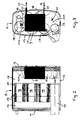
Fig. 1 benachbart zum Verbrennungsmotor 4 eingebaute und am Rahmen des Fahrgestells 2 befestigte Schalldämpfer 8 kann wie inFig. 2 und 3 dargestellt realisiert sein. Dieser Schalldämpfer 8 ist dabei tonnenförmig ausgebildet und weist einen vorderen Boden 11 und einen hinteren Boden 12, eine die beiden Böden 11, 12 verbindende hohlzylindrische Umfangsaußenwand 13, innen einen durch eine Zwischenwand 14 von einem Auslassraum 15 getrennten Einlassraum 16, ein in den Einlassraum 16 ausmündendes Einlassrohr 17 und ein Auspuffendrohr 10 auf. Das Auspuffendrohr 10 ist mit seinem Eingangsabschnitt 10a im Auslassraum 15 angeordnet und nach dem Verdampfer 9 mit seinem Ausgangsabschnitt 10b im Bereich des den Auslassraum 15 begrenzenden Boden 12 entweder durch diesen oder durch die Umfangsaußenwand 13 aus dem Schalldämpfer 8 herausgeführt. Der Verdampfer 9 ist dabei entweder in den Eingangsabschnitt 10a des Auspuffendrohres 10 eingebaut oder ersetzt einen Teil des Auspuffendrohres 10 zwischen dessen Eingangsabschnitt 10a und Ausgangsabschnitt 10b. In letzterem Fall ist der Verdampfer 9 am Boden 12 des Schalldämpfers 8 befestigt. Im dargestellten Schalldämpfer 8 sind außerdem mehrere Abgasnachbehandlungsmodule 18 angeordnet und dort durch die gasdichte Zwischenwand 14 sowie eine von dieser beabstandete gasdurchlässige Tragwand 19 gehalten. Jeder dieser Abgasnachbehandlungsmodule 18 beinhaltet in einem Gehäuse eingebaut beispielsweise einen Partikelabscheider oder -filter und/oder wenigstens einen Katalysator. Wie ausFig. 2 und 3 ersichtlich, ist in dieser Ausführungsform der Verdampfer 9 innen an dem den Auslassraum 15 begrenzenden Boden 12 des Schalldämpfers 8 befestigt. - Am Verdampfer 9 ist unten ein Anschlussstutzen 20 für die Einleitung von flüssigem Kreislaufmedium und oben ein Anschlussstutzen 21 für die Ableitung des in dampfförmigen Aggregatzustand überführten Kreislaufmediums vorgesehen. Beide Anschlussstutzen 20, 21 sind vom Verdampfer 9 ausgehend durch den benachbarten Boden 12 oder benachbarten Bereich der Umfangsaußenwand 13 des Schalldämpfers 8 hindurch aus diesem herausgeführt und dort außen mit einer durch einen Pfeil 22 symbolisierten Zuleitung für das flüssige Kreislaufmedium bzw. mit einer durch einen Pfeil 23 symbolisierten Ableitung für das dampfförmige Kreislaufmedium verbunden. In
Fig. 1 ist die Lage des Verdampfers 9 am Nutzfahrzeug 1 durch ein schwarz eingefärbtes Feld im Bereich des Schalldämpfers 8 sichtbar gemacht. - Im Fall des Fahrzeugs gemäß
Fig. 4 kommt vorzugsweise ein Schalldämpfer 8 zur Anwendung, der, wie ausFig. 5 und 6 ersichtlich, weitgehend jenen vonFig. 2 und 3 entspricht, aber den Verdampfer 9 an anderer Stelle, nämlich außen seitlich unten angebaut aufweist. Es werden daher inFig. 5 und 6 für gleiche bzw. einander entsprechende Teile die gleichen Bezugszeichen wie inFig. 2 und 3 verwendet. In diesem Beispiel ist - wie gut ausFig. 5 ersichtlich - der Verdampfer 9 in ein Gehäuse 9' integriert, das im Bereich des den Auslassraum 15 begrenzenden Bodens 12 seitlich außen unten an der Umfangsaußenwand 13 des Schalldämpfers 8 befestigt ist. In diesem Bereich weist die Umfangsaußenwand 13 des Schalldämpfers 8 einen Durchbruch auf. Das Auspuffendrohr 10 ist mit seinem intern des Auslassraumes 15 angeordneten Eingangsabschnitt 10a bis zum Verdampfer 9 hingeführt und setzt sich außerhalb des Schalldämpfers 8 ausgangs des Verdampfers 9 im Bereich einer Ausgangsöffnung 9" von dessen Gehäuse 9' mit seinem Ausgangsabschnitt 10b fort. Auch in diesem Ausführungsbeispiel weist der Verdampfer 9 einen unteren Anschlussstutzen 20, der an einer Zuleitung 22 für flüssiges Kreislaufmedium angeschlossen ist, und einen oberen Anschlussstutzen 21 auf, der an einer Ableitung 23 für das dampfförmige Medium angeschlossen ist. InFig. 4 ist die Anordnung dieses Verdampfers 9 im Nutzfahrzeug 1 ebenfalls durch ein am Schalldämpfer 8 schwarz eingefärbtes Feld sichtbar gemacht. - Im Fall des Nutzfahrzeugs gemäß
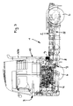
Fig. 7 kommt vorzugsweise ebenfalls ein Schalldämpfer 8 zur Anwendung, der jenen vonFig. 5, 6 entspricht, aber den Verdampfer 9 an anderer Stelle, nämlich oben außen angebaut aufweist. Es sind daher auch inFig. 7 ,8 gleiche bzw. einander entsprechende Teile mit gleichem Bezugszeichen angezogen. In diesem Beispiel ist der Verdampfer 9 - wie gut anFig. 8 ersichtlich - mit seinem Gehäuse oben an der Umfangsaußenwand 13 des Schalldämpfers 8 angebaut. In diesem Bereich weist die Umfangsaußenwand 13 des Schalldämpfers 8 einen Durchbruch auf. Das Auspuffendrohr 10 ist mit seinem Eingangsabschnitt 10a innerhalb des Auslassraumes 15 im Bereich des diesen begrenzenden Bodens 12 bis zum Verdampfer 9 hingeführt und setzt sich außerhalb des Schalldämpfers 8 ausgangs des Verdampfers 9 mit seinem im Wesentlichen vertikal hinter dem Fahrerhaus 3 angeordneten Ausgangsabschnitt 10b fort. Dieser ist durch mehrere Halter und Streben 10c lagemäßig in Bezug auf den Schalldämpfer 8 stabilisiert. - Im Fall des Nutzfahrzeugs 1 gemäß
Fig. 9 kommt der gleiche bzw. ein ähnlicher Schalldämpfer 8 wie im Nutzfahrzeug gemäßFig. 4 zur Anwendung, jedoch ist der Verdampfer 9 hier nicht am Schalldämpfer 8 angebaut, sondern in einen Endabschnitt 10b des hinter dem Fahrerhaus 3 hochgezogenen Auspuffendrohres 10 integriert, welcher Endabschnitt 10b - wie ausFig. 10 ersichtlich - sich ausgangs des Schalldämpfers 8 anschließt. Der Verdampfer 9 ist dabei entweder in diesen Auspuffendrohr-Abschnitt 10b eingebaut, und zwar vorzugsweise benachbart zum Schalldämpfer 8 oder nicht weit von diesem beabstandet, oder ersetzt den Auspuffendrohr-Abschnitt 10b partiell. Das Auspuffendrohr 10 ist dabei auch hier in Bezug auf den Schalldämpfer 8 durch spezielle Halter/Verstrebungen 10c lagestabilisiert. - Auch in den Beispielen gemäß 7, 8 und 9, 10 weist der Verdampfer 9 einen unteren Anschlussstutzen 20, an dem eine Zuleitung 22 für das flüssige Kreislaufmedium angeschlossen ist, und einen oberen Anschlussstutzen 21 auf, an dem eine Abführleitung 23 für das dampfförmige Kreislaufmedium angeschlossen ist. Die Lage dieses Verdampfers 9 am Nutzfahrzeug gemäß
Fig. 9 ist dort ebenfalls durch ein schwarz eingefärbtes Feld sichtbar gemacht. - Im Fall des Nutzfahrzeugs 1 gemäß
Fig. 11 kommt ein gegenüber den vorgenannten Varianten anderer Schalldämpfer 8 zur Anwendung. Dabei ist der Schalldämpfer 8 durch einen hinter dem Fahrerhaus 3 im Wesentlichen vertikal angeordneten Hohlzylinder 25 gebildet, der oben und unten durch je einen Boden 26 bzw. 27 verschlossen ist. Dieser Schalldämpfer 8 ist - wie gut ausFig. 12 ersichtlich - über seinen Boden 26 am zuströmseitigen Abschnitt 28/1 und über seinen Boden 27 am abströmseitigen Abschnitt 28/2 des hinter dem Fahrerhaus 3 hochgezogenen Auspuffrohres 28 angeschlossen. In diesen Schalldämpfer 8 sind der Abgasnachbehandlung dienende Katalysatoren und/oder Filter (nicht dargestellt) sowie der Verdampfer 9 integriert. Dieser Verdampfer 9 weist ebenfalls einen unteren Anschlussstutzen 20 und einen oberen Anschlussstutzen 21 auf, die durch die hohlzylindrische Wand 25 des Schalldämpfers 8 hindurch aus diesem herausführt und dort außen (20) mit der Zuleitung 22 für das flüssige Kreislaufmedium bzw. (21) mit der Ableitung 23 für das dampfförmige Kreislaufmedium verbunden sind. In diesem Beispiel ist das Auspuffrohr 28 mit dem Schalldämpfer 8 durch Halter und Verstrebungen 29 gegenüber dem zuströmseitigen Teil des Abgasstranges 7 und gegenüber dem Fahrgestell 2 lagefixiert. InFig. 11 ist die Lage des Verdampfers 9 am dortigen Nutzfahrzeug 1 ebenfalls durch ein am Schalldämpfer 8 schwarz eingefärbtes Feld kenntlich gemacht. - Der Verdampfer 9 weist eine solche Bauart und Konstruktion auf, die geeignet ist, um das über die Zuleitung 22 zugeführte flüssige Kreislaufmedium bei seiner Durchströmung unter Zuhilfenahme der thermischen Restwärmeausnutzung des vorbeiströmenden Abgases in seinen dampfförmigen Aggregatzustand zu überführen. Das zugeführte flüssige Kreislaufmedium kann, muss jedoch nicht, aufgrund eines vorherigen Wärmetausches im Wärmerückgewinnungskreislauf schon vorgewärmt sein. Das mittels des Verdampfers 9 in seinen dampfförmigen Aggregatzustand überführte Kreislaufmedium wird über die Ableitung 23 im Wärmerückgewinnungskreislauf einem Expander zugeführt, der die Dampfenergie in mechanische Energie umsetzt, welche antriebsmäßig an der Kurbelwelle des Verbrennungsmotors 4 als Zusatzantriebsleistung wirksam wird.
Claims (9)
- Nutzfahrzeug, insbesondere Lastkraftwagen, mit einem Verbrennungsmotor (4), in dessen Abgasstrang (7) ein Schalldämpfer (8) angeordnet ist, und mit einem Wärmerückgewinnungssystem, in dessen Mediumkreislauf wenigstens eine Pumpe, ein Verdampfer (9), ein Expander und ein Kondensator angeordnet sind und die Abwärme des Verbrennungsmotors (4) und/oder heißer Motoraggregate sowie heißer Betriebsmedien in leistungssteigernde Nutzenergie umwandelbar ist, dadurch gekennzeichnet, dass der im Mediumkreislauf des Wärmerückgewinnungssystems vorhandene Verdampfer (9) entweder- in den Schalldämpfer (8) integriert und dort entweder in das Auspuffendrohr (10) eingebaut ist oder dieses partiell ersetzt, oder- außen am Schalldämpfer (8) angebaut ist und sich das Auspuffendrohr (10) mit seinem Endabschnitt (10b) anschließt, oder- in das vom Schalldämpfer (8) abgehende und hinter dem Fahrerhaus (3) hochgezogene Auspuffendrohr (10) integriert und dabei entweder in dieses eingebaut ist oder dieses partiell ersetzt, oder- in einem Schalldämpfer (8) integriert ist, der in ein hinter dem Fahrerhaus (3) hochgezogenes Auspuffrohr (28) eingebaut ist.
- Nutzfahrzeug nach Anspruch 1, dadurch gekennzeichnet, dass der Schalldämpfer (8) einen vorderen Boden (11), einen hinteren Boden (12) und eine die beiden Böden (11, 12) miteinander verbindende umlaufende Umfangsaußenwand (13), außerdem einen durch eine Zwischenwand (14) von einem Einlassraum (16) getrennten Auslassraum (15), ein in den Einlassraum (16) ausmündendes Einlassrohr (17) und ein mit einem Eingangsabschnitt (10a) im Auslassraum (15) angeordnetes, dort den Verdampfer (9) aufnehmendes Auspuffendrohr (10) aufweist, das mit seinem Ausgangsabschnitt (10b) nach dem Verdampfer (9) im Bereich des den Auslassraum (15) begrenzenden Bodens (12) entweder durch diesen oder durch die Umfangsaußenwand (13) aus dem Schalldämpfer (8) herausgeführt ist.
- Nutzfahrzeug nach Anspruch 2, dadurch gekennzeichnet, dass der Verdampfer (9) innen an dem den Auslassraum (15) begrenzenden Boden (12) des Schalldämpfers (8) befestigt ist.
- Nutzfahrzeug nach einem der Ansprüche 2 und 3, dadurch gekennzeichnet, dass am Verdampfer (9) ein für die Einspeisung des flüssigen Kreislaufmediums dienender Anschlussstutzen (20) und ein für die Ableitung des in dampfförmigen Aggregatzustand überführten Kreislaufmediums dienender Anschlussstutzen (21) angeordnet sind, welche Anschlussstutzen (20, 21) vom Verdampfer (9) ausgehend durch den benachbarten Boden (12) oder benachbarten Bereich der Umfangsaußenwand (13) des Schalldämpfers (8) hindurch aus diesem herausgeführt und dort (20) mit einer Zuleitung (22) für das flüssige Kreislaufmedium beziehungsweise (21) mit einer Ableitung (25) für das dampfförmige Kreislaufmedium verbunden sind.
- Nutzfahrzeug nach Anspruch 1, dadurch gekennzeichnet, dass der Schalldämpfer (8) einen vorderen Boden (11), einen hinteren Boden (12) und eine Umfangaußenwand (13), außerdem ein Einlassrohr (17) und ein Auspuffendrohr (10) aufweist, das im Bereich eines Bodens (11, 12) entweder durch diesen oder durch die Umfangsaußenwand (13) aus dem Schalldämpfer (8) herausgeführt und dann nach dem dort außen am Schalldämpfer (8) angebauten Verdampfer (9) weitergeführt ist.
- Nutzfahrzeug nach Anspruch 1, dadurch gekennzeichnet, dass der Schalldämpfer (8) einen vorderen Boden (11), einen hinteren Boden (12) und eine die beiden Böden (11, 12) miteinander verbindende Umfangsaußenwand (13), außerdem ein Einlassrohr (7) und ein Auspuffendrohr (10) aufweist, das im Bereich eines Bodens (11, 12) entweder durch diesen oder durch die Umfangsaußenwand (13) aus dem Schalldämpfer (8) herausgeführt und dann hinter dem Fahrerhaus (3) hochgezogen ist, und dass der Verdampfer (9) benachbart zum Schalldämpfer (8) beziehungsweise nicht weit von diesem beabstandet in einen Abschnitt (10b) des Auspuffendrohrs (10) integriert ist, wobei der Verdampfer (9) in diesen Auspuffendrohr-Abschnitt (10b) entweder eingebaut ist oder den Endrohr-Abschnitt (10b) partiell ersetzt.
- Nutzfahrzeug nach einem der Ansprüche 5 und 6, dadurch gekennzeichnet, dass der Verdampfer (9) einen mit einer Zuleitung (22) für flüssiges Kreislaufmedium verbundenen Anschlussstutzen (20) und einen mit einer Ableitung (23) für das in dampfförmigen Aggregatzustand überführte Kreislaufmedium verbundenen Anschlussstutzen (21) aufweist.
- Nutzfahrzeug nach Anspruch 1, dadurch gekennzeichnet, dass der Schalldämpfer (8) durch einen hinter dem Fahrerhaus (3) im Wesentlichen vertikal angeordneten Hohlzylinder (25) gebildet ist, der oben und unten durch je einen Boden (26, 27) verschlossen und über diese Böden (26, 27) einerseits am zuströmseitigen Abschnitt (28/1), andererseits am abströmseitigen Abschnitt (28/2) eines hinter dem Fahrerhaus (3) hochgezogenen Auspuffrohres (28) angeschlossen ist, dass in diesen Schalldämpfer (8) der Verdampfer (9) integriert ist, und dass ein Anschlussstutzen (20) für die Einspeisung des flüssigen Kreislaufmediums und ein Anschlussstutzen (21) für die Ableitung des in dampfförmigen Aggregatzustand überführten Kreislaufmediums vom Verdampfer (9) ausgehend durch die hohlzylindrische Wand (25) des Schalldämpfers (8) hindurch seitlich aus diesem herausgeführt und dort außen (20) mit einer Zuleitung für das flüssige Kreislaufmedium bzw. (21) mit einer Ableitung (23) für das dampfförmige Kreislaufmedium verbunden sind.
- Nutzfahrzeug nach einem der vorhergehenden Ansprüche, dadurch gekennzeichnet, dass das dem Verdampfer (9) in flüssigem Zustand zugeführte und mittels diesem unter Ausnutzung der Wärmeenergie des Abgases in dampfförmigen Aggregatzustand überführte Kreislaufmedium über die Ableitung (23) einen Expander zuführbar ist, der die Dampfenergie in mechanische Energie umsetzt, welche antriebsmäßig an der Kurbelwelle des Verbrennungsmotors (4) als Zusatzantriebsleistung wirksam wird.
Priority Applications (1)
| Application Number | Priority Date | Filing Date | Title |
|---|---|---|---|
| PL09002006T PL2110527T3 (pl) | 2008-04-14 | 2009-02-13 | Pojazd użytkowy z silnikiem spalinowym i wykorzystującym jego źródła ciepła systemem odzyskiwania ciepła |
Applications Claiming Priority (1)
| Application Number | Priority Date | Filing Date | Title |
|---|---|---|---|
| AT0057608A AT505547B1 (de) | 2008-04-14 | 2008-04-14 | Nutzfahrzeug mit einem verbrennungsmotor und einem dessen wärmequellen ausnutzenden wärmerückgewinnungssystem |
Publications (3)
| Publication Number | Publication Date |
|---|---|
| EP2110527A2 true EP2110527A2 (de) | 2009-10-21 |
| EP2110527A3 EP2110527A3 (de) | 2010-02-24 |
| EP2110527B1 EP2110527B1 (de) | 2012-01-04 |
Family
ID=40373461
Family Applications (1)
| Application Number | Title | Priority Date | Filing Date |
|---|---|---|---|
| EP09002006A Not-in-force EP2110527B1 (de) | 2008-04-14 | 2009-02-13 | Nutzfahrzeug mit einem Verbrennungsmotor und einem dessen Wärmequellen ausnutzenden Wärmerückgewinnungssystem |
Country Status (7)
| Country | Link |
|---|---|
| US (1) | US8707688B2 (de) |
| EP (1) | EP2110527B1 (de) |
| CN (1) | CN101607524B (de) |
| AT (2) | AT505547B1 (de) |
| BR (1) | BRPI0901355B1 (de) |
| PL (1) | PL2110527T3 (de) |
| RU (1) | RU2412851C2 (de) |
Cited By (1)
| Publication number | Priority date | Publication date | Assignee | Title |
|---|---|---|---|---|
| US10240488B2 (en) | 2014-04-30 | 2019-03-26 | MAHLE Behr GmbH & Co. KG | Exhaust gas system for a motor vehicle |
Families Citing this family (9)
| Publication number | Priority date | Publication date | Assignee | Title |
|---|---|---|---|---|
| US8230678B2 (en) * | 2007-06-21 | 2012-07-31 | Daimler Trucks North America Llc | Treatment of diesel engine exhaust |
| US8397504B2 (en) * | 2010-02-08 | 2013-03-19 | Global Alternative Fuels, Llc | Method and apparatus to recover and convert waste heat to mechanical energy |
| SE535680C2 (sv) * | 2011-03-17 | 2012-11-06 | Scania Cv Ab | Arrangemang för att omvandla värmeenergi till mekanisk energi i ett fordon |
| EP2662545B1 (de) | 2012-05-11 | 2016-12-28 | Caterpillar Motoren GmbH & Co. KG | Strahlungswärmeabgabeanordnung |
| DE102013012852A1 (de) | 2013-08-02 | 2015-02-05 | Daimler Ag | Vorrichtung zur Energierückgewinnung aus einem Abgasstrom einer Verbrennungskraftmaschine |
| AT517965B1 (de) * | 2016-03-22 | 2017-06-15 | MAN Truck & Bus Österreich AG | Anordnung von Nebenaggregaten bei einer Brennkraftmaschine |
| US11136905B2 (en) * | 2017-09-22 | 2021-10-05 | Tenneco Gmbh | Rankine power system with working fluid tank and control system |
| CN113339326B (zh) * | 2021-06-08 | 2023-11-14 | 江苏悦达专用车有限公司 | 一种水泵加热系统 |
| CN118596825A (zh) * | 2024-06-20 | 2024-09-06 | 东风商用车有限公司 | 一种车辆排气系统及汽车 |
Citations (3)
| Publication number | Priority date | Publication date | Assignee | Title |
|---|---|---|---|---|
| DE4141061A1 (de) | 1991-12-13 | 1993-06-17 | Schaeffler Waelzlager Kg | Verfahren und vorrichtung zur herstellung eines mit waelzkoerpern gefuellten waelzlagerkaefigs |
| WO2000031400A2 (en) | 1998-11-24 | 2000-06-02 | Claudio Filippone | Miniaturized waste heat engine |
| EP1249585A1 (de) | 2000-01-21 | 2002-10-16 | Honda Giken Kogyo Kabushiki Kaisha | Wärmetauscher einer mehrzylindrigen brennkraftmaschine |
Family Cites Families (16)
| Publication number | Priority date | Publication date | Assignee | Title |
|---|---|---|---|---|
| US3280903A (en) * | 1964-12-21 | 1966-10-25 | Universal Silencer Corp | Exhaust silencer and heat recovery unit |
| US3501095A (en) * | 1968-03-13 | 1970-03-17 | Randall A Peterson | Hot air heating apparatus for tractor |
| IT1003514B (it) * | 1971-04-05 | 1976-06-10 | Shuffman O | Apparato per la purifi cazione di gas di combustione |
| US3748830A (en) * | 1972-05-19 | 1973-07-31 | Ross S | Method and apparatus for purifying combustion gases |
| JPS6131131Y2 (de) * | 1981-03-26 | 1986-09-10 | ||
| SU1671921A1 (ru) * | 1989-05-23 | 1991-08-23 | Белорусский технологический институт им.С.М.Кирова | Двигатель внутреннего сгорани |
| DE4141051A1 (de) * | 1991-12-13 | 1993-06-17 | Wojciech Slomkowski | Brennkraftmaschine mit einer dampfturbinenanlage als leistungsgekoppelter zusatzeinrichtung |
| DE60113646T2 (de) * | 2000-01-21 | 2006-03-16 | Honda Giken Kogyo K.K. | Abgasreinigungsvorrichtung und brennkraftmaschine |
| CN2481853Y (zh) * | 2001-06-18 | 2002-03-13 | 戴中华 | 发动机热能、废气能量回收再利用装置 |
| US6951697B2 (en) * | 2001-09-11 | 2005-10-04 | Donaldson Company, Inc. | Integrated systems for use with fuel cells, and methods |
| US6871489B2 (en) * | 2003-04-16 | 2005-03-29 | Arvin Technologies, Inc. | Thermal management of exhaust systems |
| DE10340105A1 (de) * | 2003-08-30 | 2005-03-24 | Man Nutzfahrzeuge Ag | Abgasstrang einer Brennkraftmaschine mit eingebautem Vor- und Hauptschalldämpfer |
| BRPI0511051A (pt) * | 2004-05-11 | 2007-11-27 | Modine Mfg Co | unidade integrada de trocador de calor e silencioso |
| US7063134B2 (en) * | 2004-06-24 | 2006-06-20 | Tenneco Automotive Operating Company Inc. | Combined muffler/heat exchanger |
| GB0618867D0 (en) * | 2006-09-25 | 2006-11-01 | Univ Sussex The | Vehicle power supply system |
| CN101059108A (zh) * | 2007-06-06 | 2007-10-24 | 上海毅知实业有限公司 | 车用内燃机余热回收利用机构及方法 |
-
2008
- 2008-04-14 AT AT0057608A patent/AT505547B1/de not_active IP Right Cessation
-
2009
- 2009-02-13 EP EP09002006A patent/EP2110527B1/de not_active Not-in-force
- 2009-02-13 AT AT09002006T patent/ATE540207T1/de active
- 2009-02-13 PL PL09002006T patent/PL2110527T3/pl unknown
- 2009-04-13 RU RU2009113833/11A patent/RU2412851C2/ru active
- 2009-04-14 BR BRPI0901355A patent/BRPI0901355B1/pt not_active IP Right Cessation
- 2009-04-14 US US12/423,149 patent/US8707688B2/en not_active Expired - Fee Related
- 2009-04-14 CN CN200910132727.4A patent/CN101607524B/zh not_active Expired - Fee Related
Patent Citations (3)
| Publication number | Priority date | Publication date | Assignee | Title |
|---|---|---|---|---|
| DE4141061A1 (de) | 1991-12-13 | 1993-06-17 | Schaeffler Waelzlager Kg | Verfahren und vorrichtung zur herstellung eines mit waelzkoerpern gefuellten waelzlagerkaefigs |
| WO2000031400A2 (en) | 1998-11-24 | 2000-06-02 | Claudio Filippone | Miniaturized waste heat engine |
| EP1249585A1 (de) | 2000-01-21 | 2002-10-16 | Honda Giken Kogyo Kabushiki Kaisha | Wärmetauscher einer mehrzylindrigen brennkraftmaschine |
Cited By (1)
| Publication number | Priority date | Publication date | Assignee | Title |
|---|---|---|---|---|
| US10240488B2 (en) | 2014-04-30 | 2019-03-26 | MAHLE Behr GmbH & Co. KG | Exhaust gas system for a motor vehicle |
Also Published As
| Publication number | Publication date |
|---|---|
| ATE540207T1 (de) | 2012-01-15 |
| RU2412851C2 (ru) | 2011-02-27 |
| EP2110527B1 (de) | 2012-01-04 |
| BRPI0901355B1 (pt) | 2020-05-05 |
| US20090255243A1 (en) | 2009-10-15 |
| PL2110527T3 (pl) | 2012-06-29 |
| CN101607524B (zh) | 2014-03-05 |
| US8707688B2 (en) | 2014-04-29 |
| BRPI0901355A2 (pt) | 2009-12-01 |
| AT505547B1 (de) | 2009-02-15 |
| CN101607524A (zh) | 2009-12-23 |
| RU2009113833A (ru) | 2010-10-20 |
| EP2110527A3 (de) | 2010-02-24 |
| AT505547A4 (de) | 2009-02-15 |
Similar Documents
| Publication | Publication Date | Title |
|---|---|---|
| EP2110527B1 (de) | Nutzfahrzeug mit einem Verbrennungsmotor und einem dessen Wärmequellen ausnutzenden Wärmerückgewinnungssystem | |
| EP2156041B1 (de) | Antriebsstrang, insbesondere für lkw und schienenfahrzeuge | |
| DE102017213004A1 (de) | Brennkraftmaschine | |
| DE102011105041B4 (de) | Schmiervorrichtung für einen Turbolader eines Motors für ein Fahrzeug | |
| DE102011104450A1 (de) | Turboladevorrichtung für einen Fahrzeugmotor | |
| EP2625415A1 (de) | Abgasrückführfilter, brennkraftmaschine | |
| DE102014117007A1 (de) | Kühlmodul einer Fahrzeugklimaanlage sowie Baugruppe zur Kühlung eines Kraftfahrzeugmotors mit einem solchen Kühlmodul | |
| DE102007025173A1 (de) | Anordnung von Aufladebaueinheiten zum Aufladen einer Verbrennungskraftmaschine | |
| WO2008101978A1 (de) | Frischgasmodul für eine frischgasanlage | |
| EP1203142A1 (de) | Brennkraftmaschine mit sekundärlufteinblassystem | |
| EP2157309B1 (de) | Brennkraftmaschine | |
| DE102023000093A1 (de) | Drucklufterzeugungseinheit zum Erzeugen von Druckluft für ein pneumatisches System eines Fahrzeugs sowie batterieelektrisch betriebenes Fahrzeug mit zumindest einem pneumatischen System mit zumindest einer solchen Drucklufterzeugungseinheit | |
| EP3225811B1 (de) | Anordnung von nebenaggregaten bei einer brennkraftmaschine | |
| EP3225810B1 (de) | Nebentrieb einer brennkraftmaschine | |
| DE102010063265A1 (de) | Ladeluftkühler | |
| DE19849619B4 (de) | Kühlsystem für einen Verbrennungsmotor eines Kraftfahrzeuges | |
| DE102016013926A1 (de) | Kühlvorrichtung zum Kühlen von Ladeluft für eine Verbrennungskraftmaschine | |
| DE102014005251A1 (de) | Vorrichtung zum Betreiben eines Verbrennungsmotors | |
| DE102013211701A1 (de) | Fahrzeugheizsystem sowie Verfahren zum Heizen des Innenraums eines Fahrzeugs mit einem Fahrzeugheizsystem | |
| DE102019004384A1 (de) | Vorrichtung und Verfahren zur Reinigung von Abgasen | |
| DE102009057802B4 (de) | Kühlkreislauf für eine Brennkraftmaschine | |
| DE102014201937A1 (de) | Ladeluftkühler | |
| DE102016012355A1 (de) | Verbrennungskraftmaschine für ein Kraftfahrzeug, insbesondere für einen Kraftwagen | |
| DE102016213590A1 (de) | Brennkraftmaschine mit Ladeluftkühlung durch Klimaanlagensystem | |
| DE202013102685U1 (de) | Fahrzeugheizsystem zum Heizen des Innenraums eines Fahrzeugs |
Legal Events
| Date | Code | Title | Description |
|---|---|---|---|
| PUAI | Public reference made under article 153(3) epc to a published international application that has entered the european phase |
Free format text: ORIGINAL CODE: 0009012 |
|
| AK | Designated contracting states |
Kind code of ref document: A2 Designated state(s): AT BE BG CH CY CZ DE DK EE ES FI FR GB GR HR HU IE IS IT LI LT LU LV MC MK MT NL NO PL PT RO SE SI SK TR |
|
| AX | Request for extension of the european patent |
Extension state: AL BA RS |
|
| PUAL | Search report despatched |
Free format text: ORIGINAL CODE: 0009013 |
|
| AK | Designated contracting states |
Kind code of ref document: A3 Designated state(s): AT BE BG CH CY CZ DE DK EE ES FI FR GB GR HR HU IE IS IT LI LT LU LV MC MK MT NL NO PL PT RO SE SI SK TR |
|
| AX | Request for extension of the european patent |
Extension state: AL BA RS |
|
| 17P | Request for examination filed |
Effective date: 20100315 |
|
| 17Q | First examination report despatched |
Effective date: 20100422 |
|
| AKX | Designation fees paid |
Designated state(s): AT BE BG CH CY CZ DE DK EE ES FI FR GB GR HR HU IE IS IT LI LT LU LV MC MK MT NL NO PL PT RO SE SI SK TR |
|
| RIC1 | Information provided on ipc code assigned before grant |
Ipc: F01N 1/08 20060101ALI20110715BHEP Ipc: F01N 5/02 20060101AFI20110715BHEP Ipc: F02G 5/02 20060101ALI20110715BHEP |
|
| GRAP | Despatch of communication of intention to grant a patent |
Free format text: ORIGINAL CODE: EPIDOSNIGR1 |
|
| GRAS | Grant fee paid |
Free format text: ORIGINAL CODE: EPIDOSNIGR3 |
|
| GRAA | (expected) grant |
Free format text: ORIGINAL CODE: 0009210 |
|
| AK | Designated contracting states |
Kind code of ref document: B1 Designated state(s): AT BE BG CH CY CZ DE DK EE ES FI FR GB GR HR HU IE IS IT LI LT LU LV MC MK MT NL NO PL PT RO SE SI SK TR |
|
| REG | Reference to a national code |
Ref country code: GB Ref legal event code: FG4D Free format text: NOT ENGLISH |
|
| REG | Reference to a national code |
Ref country code: CH Ref legal event code: EP |
|
| REG | Reference to a national code |
Ref country code: AT Ref legal event code: REF Ref document number: 540207 Country of ref document: AT Kind code of ref document: T Effective date: 20120115 |
|
| REG | Reference to a national code |
Ref country code: IE Ref legal event code: FG4D |
|
| RAP2 | Party data changed (patent owner data changed or rights of a patent transferred) |
Owner name: MAN TRUCK & BUS OESTERREICH AG |
|
| REG | Reference to a national code |
Ref country code: NL Ref legal event code: TD Effective date: 20120223 |
|
| REG | Reference to a national code |
Ref country code: DE Ref legal event code: R096 Ref document number: 502009002345 Country of ref document: DE Effective date: 20120308 |
|
| REG | Reference to a national code |
Ref country code: NL Ref legal event code: T3 |
|
| REG | Reference to a national code |
Ref country code: DE Ref legal event code: R081 Ref document number: 502009002345 Country of ref document: DE Owner name: MAN TRUCK & BUS OESTERREICH AG, AT Free format text: FORMER OWNER: MAN NUTZFAHRZEUGE OESTERREICH AG, STEYR, AT Effective date: 20120125 |
|
| REG | Reference to a national code |
Ref country code: SE Ref legal event code: TRGR |
|
| PG25 | Lapsed in a contracting state [announced via postgrant information from national office to epo] |
Ref country code: SI Free format text: LAPSE BECAUSE OF FAILURE TO SUBMIT A TRANSLATION OF THE DESCRIPTION OR TO PAY THE FEE WITHIN THE PRESCRIBED TIME-LIMIT Effective date: 20120104 |
|
| LTIE | Lt: invalidation of european patent or patent extension |
Effective date: 20120104 |
|
| REG | Reference to a national code |
Ref country code: PL Ref legal event code: T3 |
|
| PG25 | Lapsed in a contracting state [announced via postgrant information from national office to epo] |
Ref country code: BG Free format text: LAPSE BECAUSE OF FAILURE TO SUBMIT A TRANSLATION OF THE DESCRIPTION OR TO PAY THE FEE WITHIN THE PRESCRIBED TIME-LIMIT Effective date: 20120404 Ref country code: IS Free format text: LAPSE BECAUSE OF FAILURE TO SUBMIT A TRANSLATION OF THE DESCRIPTION OR TO PAY THE FEE WITHIN THE PRESCRIBED TIME-LIMIT Effective date: 20120504 Ref country code: HR Free format text: LAPSE BECAUSE OF FAILURE TO SUBMIT A TRANSLATION OF THE DESCRIPTION OR TO PAY THE FEE WITHIN THE PRESCRIBED TIME-LIMIT Effective date: 20120104 Ref country code: LT Free format text: LAPSE BECAUSE OF FAILURE TO SUBMIT A TRANSLATION OF THE DESCRIPTION OR TO PAY THE FEE WITHIN THE PRESCRIBED TIME-LIMIT Effective date: 20120104 Ref country code: NO Free format text: LAPSE BECAUSE OF FAILURE TO SUBMIT A TRANSLATION OF THE DESCRIPTION OR TO PAY THE FEE WITHIN THE PRESCRIBED TIME-LIMIT Effective date: 20120404 |
|
| REG | Reference to a national code |
Ref country code: IE Ref legal event code: FD4D |
|
| BERE | Be: lapsed |
Owner name: MAN NUTZFAHRZEUGE OSTERREICH AG Effective date: 20120228 |
|
| PG25 | Lapsed in a contracting state [announced via postgrant information from national office to epo] |
Ref country code: LV Free format text: LAPSE BECAUSE OF FAILURE TO SUBMIT A TRANSLATION OF THE DESCRIPTION OR TO PAY THE FEE WITHIN THE PRESCRIBED TIME-LIMIT Effective date: 20120104 Ref country code: PT Free format text: LAPSE BECAUSE OF FAILURE TO SUBMIT A TRANSLATION OF THE DESCRIPTION OR TO PAY THE FEE WITHIN THE PRESCRIBED TIME-LIMIT Effective date: 20120504 Ref country code: GR Free format text: LAPSE BECAUSE OF FAILURE TO SUBMIT A TRANSLATION OF THE DESCRIPTION OR TO PAY THE FEE WITHIN THE PRESCRIBED TIME-LIMIT Effective date: 20120405 Ref country code: FI Free format text: LAPSE BECAUSE OF FAILURE TO SUBMIT A TRANSLATION OF THE DESCRIPTION OR TO PAY THE FEE WITHIN THE PRESCRIBED TIME-LIMIT Effective date: 20120104 |
|
| PG25 | Lapsed in a contracting state [announced via postgrant information from national office to epo] |
Ref country code: MC Free format text: LAPSE BECAUSE OF NON-PAYMENT OF DUE FEES Effective date: 20120229 Ref country code: CY Free format text: LAPSE BECAUSE OF FAILURE TO SUBMIT A TRANSLATION OF THE DESCRIPTION OR TO PAY THE FEE WITHIN THE PRESCRIBED TIME-LIMIT Effective date: 20120104 |
|
| PG25 | Lapsed in a contracting state [announced via postgrant information from national office to epo] |
Ref country code: RO Free format text: LAPSE BECAUSE OF FAILURE TO SUBMIT A TRANSLATION OF THE DESCRIPTION OR TO PAY THE FEE WITHIN THE PRESCRIBED TIME-LIMIT Effective date: 20120104 Ref country code: IE Free format text: LAPSE BECAUSE OF FAILURE TO SUBMIT A TRANSLATION OF THE DESCRIPTION OR TO PAY THE FEE WITHIN THE PRESCRIBED TIME-LIMIT Effective date: 20120104 Ref country code: DK Free format text: LAPSE BECAUSE OF FAILURE TO SUBMIT A TRANSLATION OF THE DESCRIPTION OR TO PAY THE FEE WITHIN THE PRESCRIBED TIME-LIMIT Effective date: 20120104 Ref country code: EE Free format text: LAPSE BECAUSE OF FAILURE TO SUBMIT A TRANSLATION OF THE DESCRIPTION OR TO PAY THE FEE WITHIN THE PRESCRIBED TIME-LIMIT Effective date: 20120104 Ref country code: CZ Free format text: LAPSE BECAUSE OF FAILURE TO SUBMIT A TRANSLATION OF THE DESCRIPTION OR TO PAY THE FEE WITHIN THE PRESCRIBED TIME-LIMIT Effective date: 20120104 |
|
| PLBE | No opposition filed within time limit |
Free format text: ORIGINAL CODE: 0009261 |
|
| STAA | Information on the status of an ep patent application or granted ep patent |
Free format text: STATUS: NO OPPOSITION FILED WITHIN TIME LIMIT |
|
| PG25 | Lapsed in a contracting state [announced via postgrant information from national office to epo] |
Ref country code: SK Free format text: LAPSE BECAUSE OF FAILURE TO SUBMIT A TRANSLATION OF THE DESCRIPTION OR TO PAY THE FEE WITHIN THE PRESCRIBED TIME-LIMIT Effective date: 20120104 |
|
| 26N | No opposition filed |
Effective date: 20121005 |
|
| PG25 | Lapsed in a contracting state [announced via postgrant information from national office to epo] |
Ref country code: BE Free format text: LAPSE BECAUSE OF NON-PAYMENT OF DUE FEES Effective date: 20120228 |
|
| REG | Reference to a national code |
Ref country code: DE Ref legal event code: R097 Ref document number: 502009002345 Country of ref document: DE Effective date: 20121005 |
|
| PG25 | Lapsed in a contracting state [announced via postgrant information from national office to epo] |
Ref country code: MK Free format text: LAPSE BECAUSE OF FAILURE TO SUBMIT A TRANSLATION OF THE DESCRIPTION OR TO PAY THE FEE WITHIN THE PRESCRIBED TIME-LIMIT Effective date: 20120104 |
|
| PG25 | Lapsed in a contracting state [announced via postgrant information from national office to epo] |
Ref country code: ES Free format text: LAPSE BECAUSE OF FAILURE TO SUBMIT A TRANSLATION OF THE DESCRIPTION OR TO PAY THE FEE WITHIN THE PRESCRIBED TIME-LIMIT Effective date: 20120415 |
|
| PG25 | Lapsed in a contracting state [announced via postgrant information from national office to epo] |
Ref country code: MT Free format text: LAPSE BECAUSE OF FAILURE TO SUBMIT A TRANSLATION OF THE DESCRIPTION OR TO PAY THE FEE WITHIN THE PRESCRIBED TIME-LIMIT Effective date: 20120104 |
|
| REG | Reference to a national code |
Ref country code: CH Ref legal event code: PL |
|
| GBPC | Gb: european patent ceased through non-payment of renewal fee |
Effective date: 20130213 |
|
| PG25 | Lapsed in a contracting state [announced via postgrant information from national office to epo] |
Ref country code: LI Free format text: LAPSE BECAUSE OF NON-PAYMENT OF DUE FEES Effective date: 20130228 Ref country code: CH Free format text: LAPSE BECAUSE OF NON-PAYMENT OF DUE FEES Effective date: 20130228 |
|
| PG25 | Lapsed in a contracting state [announced via postgrant information from national office to epo] |
Ref country code: GB Free format text: LAPSE BECAUSE OF NON-PAYMENT OF DUE FEES Effective date: 20130213 |
|
| PG25 | Lapsed in a contracting state [announced via postgrant information from national office to epo] |
Ref country code: LU Free format text: LAPSE BECAUSE OF NON-PAYMENT OF DUE FEES Effective date: 20120213 |
|
| PG25 | Lapsed in a contracting state [announced via postgrant information from national office to epo] |
Ref country code: HU Free format text: LAPSE BECAUSE OF FAILURE TO SUBMIT A TRANSLATION OF THE DESCRIPTION OR TO PAY THE FEE WITHIN THE PRESCRIBED TIME-LIMIT Effective date: 20090213 |
|
| REG | Reference to a national code |
Ref country code: AT Ref legal event code: MM01 Ref document number: 540207 Country of ref document: AT Kind code of ref document: T Effective date: 20140213 |
|
| PG25 | Lapsed in a contracting state [announced via postgrant information from national office to epo] |
Ref country code: AT Free format text: LAPSE BECAUSE OF NON-PAYMENT OF DUE FEES Effective date: 20140213 |
|
| REG | Reference to a national code |
Ref country code: FR Ref legal event code: PLFP Year of fee payment: 8 |
|
| REG | Reference to a national code |
Ref country code: FR Ref legal event code: PLFP Year of fee payment: 9 |
|
| REG | Reference to a national code |
Ref country code: FR Ref legal event code: PLFP Year of fee payment: 10 |
|
| REG | Reference to a national code |
Ref country code: DE Ref legal event code: R081 Ref document number: 502009002345 Country of ref document: DE Owner name: MAN TRUCK & BUS SE, DE Free format text: FORMER OWNER: MAN TRUCK & BUS OESTERREICH AG, STEYR, AT |
|
| PGFP | Annual fee paid to national office [announced via postgrant information from national office to epo] |
Ref country code: NL Payment date: 20230222 Year of fee payment: 15 |
|
| PGFP | Annual fee paid to national office [announced via postgrant information from national office to epo] |
Ref country code: FR Payment date: 20230223 Year of fee payment: 15 |
|
| PGFP | Annual fee paid to national office [announced via postgrant information from national office to epo] |
Ref country code: TR Payment date: 20230201 Year of fee payment: 15 Ref country code: SE Payment date: 20230222 Year of fee payment: 15 Ref country code: PL Payment date: 20230203 Year of fee payment: 15 Ref country code: IT Payment date: 20230220 Year of fee payment: 15 Ref country code: DE Payment date: 20230227 Year of fee payment: 15 |
|
| REG | Reference to a national code |
Ref country code: NL Ref legal event code: PD Owner name: MAN TRUCK & BUS OESTERREICH GESMBH; AT Free format text: DETAILS ASSIGNMENT: CHANGE OF OWNER(S), ASSIGNMENT; FORMER OWNER NAME: MAN TRUCK & BUS OESTERREICH GESMBH Effective date: 20231031 |
|
| REG | Reference to a national code |
Ref country code: DE Ref legal event code: R119 Ref document number: 502009002345 Country of ref document: DE |
|
| REG | Reference to a national code |
Ref country code: SE Ref legal event code: EUG |
|
| REG | Reference to a national code |
Ref country code: NL Ref legal event code: MM Effective date: 20240301 |
|
| PG25 | Lapsed in a contracting state [announced via postgrant information from national office to epo] |
Ref country code: NL Free format text: LAPSE BECAUSE OF NON-PAYMENT OF DUE FEES Effective date: 20240301 |
|
| PG25 | Lapsed in a contracting state [announced via postgrant information from national office to epo] |
Ref country code: NL Free format text: LAPSE BECAUSE OF NON-PAYMENT OF DUE FEES Effective date: 20240301 |
|
| PG25 | Lapsed in a contracting state [announced via postgrant information from national office to epo] |
Ref country code: DE Free format text: LAPSE BECAUSE OF NON-PAYMENT OF DUE FEES Effective date: 20240903 |
|
| PG25 | Lapsed in a contracting state [announced via postgrant information from national office to epo] |
Ref country code: FR Free format text: LAPSE BECAUSE OF NON-PAYMENT OF DUE FEES Effective date: 20240229 |
|
| PG25 | Lapsed in a contracting state [announced via postgrant information from national office to epo] |
Ref country code: FR Free format text: LAPSE BECAUSE OF NON-PAYMENT OF DUE FEES Effective date: 20240229 Ref country code: DE Free format text: LAPSE BECAUSE OF NON-PAYMENT OF DUE FEES Effective date: 20240903 |
|
| PG25 | Lapsed in a contracting state [announced via postgrant information from national office to epo] |
Ref country code: IT Free format text: LAPSE BECAUSE OF NON-PAYMENT OF DUE FEES Effective date: 20240213 |
|
| PG25 | Lapsed in a contracting state [announced via postgrant information from national office to epo] |
Ref country code: PL Free format text: LAPSE BECAUSE OF NON-PAYMENT OF DUE FEES Effective date: 20240213 |
|
| PG25 | Lapsed in a contracting state [announced via postgrant information from national office to epo] |
Ref country code: SE Free format text: LAPSE BECAUSE OF NON-PAYMENT OF DUE FEES Effective date: 20240214 |
|
| PG25 | Lapsed in a contracting state [announced via postgrant information from national office to epo] |
Ref country code: TR Free format text: LAPSE BECAUSE OF NON-PAYMENT OF DUE FEES Effective date: 20240213 |