EP1249907A2 - Befestigungsanordnung einer Zündkerze und Zündkerze dafür - Google Patents
Befestigungsanordnung einer Zündkerze und Zündkerze dafür Download PDFInfo
- Publication number
- EP1249907A2 EP1249907A2 EP02008397A EP02008397A EP1249907A2 EP 1249907 A2 EP1249907 A2 EP 1249907A2 EP 02008397 A EP02008397 A EP 02008397A EP 02008397 A EP02008397 A EP 02008397A EP 1249907 A2 EP1249907 A2 EP 1249907A2
- Authority
- EP
- European Patent Office
- Prior art keywords
- plug
- spark plug
- end portion
- metallic shell
- clearance
- Prior art date
- Legal status (The legal status is an assumption and is not a legal conclusion. Google has not performed a legal analysis and makes no representation as to the accuracy of the status listed.)
- Granted
Links
- 239000000565 sealant Substances 0.000 claims abstract description 45
- 239000012212 insulator Substances 0.000 claims abstract description 36
- 239000000919 ceramic Substances 0.000 claims description 12
- 229910052751 metal Inorganic materials 0.000 claims description 12
- 239000002184 metal Substances 0.000 claims description 12
- 239000000956 alloy Substances 0.000 claims description 10
- 229910045601 alloy Inorganic materials 0.000 claims description 10
- 239000000463 material Substances 0.000 claims description 7
- 230000003247 decreasing effect Effects 0.000 claims description 3
- 238000002485 combustion reaction Methods 0.000 description 14
- 239000000843 powder Substances 0.000 description 13
- 238000012856 packing Methods 0.000 description 6
- 239000000203 mixture Substances 0.000 description 5
- 238000004804 winding Methods 0.000 description 5
- 150000002500 ions Chemical class 0.000 description 4
- 239000000567 combustion gas Substances 0.000 description 3
- 239000013013 elastic material Substances 0.000 description 3
- 239000000446 fuel Substances 0.000 description 3
- 238000012360 testing method Methods 0.000 description 3
- 239000011345 viscous material Substances 0.000 description 3
- RYGMFSIKBFXOCR-UHFFFAOYSA-N Copper Chemical compound [Cu] RYGMFSIKBFXOCR-UHFFFAOYSA-N 0.000 description 2
- 239000011521 glass Substances 0.000 description 2
- 239000002480 mineral oil Substances 0.000 description 2
- 235000010446 mineral oil Nutrition 0.000 description 2
- 238000007789 sealing Methods 0.000 description 2
- 229910052582 BN Inorganic materials 0.000 description 1
- PZNSFCLAULLKQX-UHFFFAOYSA-N Boron nitride Chemical compound N#B PZNSFCLAULLKQX-UHFFFAOYSA-N 0.000 description 1
- 229910000975 Carbon steel Inorganic materials 0.000 description 1
- ZOKXTWBITQBERF-UHFFFAOYSA-N Molybdenum Chemical compound [Mo] ZOKXTWBITQBERF-UHFFFAOYSA-N 0.000 description 1
- 239000002253 acid Substances 0.000 description 1
- XAGFODPZIPBFFR-UHFFFAOYSA-N aluminium Chemical compound [Al] XAGFODPZIPBFFR-UHFFFAOYSA-N 0.000 description 1
- 230000004888 barrier function Effects 0.000 description 1
- 239000010962 carbon steel Substances 0.000 description 1
- 230000006835 compression Effects 0.000 description 1
- 238000007906 compression Methods 0.000 description 1
- 239000002826 coolant Substances 0.000 description 1
- 238000001816 cooling Methods 0.000 description 1
- PMHQVHHXPFUNSP-UHFFFAOYSA-M copper(1+);methylsulfanylmethane;bromide Chemical compound Br[Cu].CSC PMHQVHHXPFUNSP-UHFFFAOYSA-M 0.000 description 1
- 238000013461 design Methods 0.000 description 1
- 238000006073 displacement reaction Methods 0.000 description 1
- 238000010292 electrical insulation Methods 0.000 description 1
- 150000002148 esters Chemical class 0.000 description 1
- 238000011156 evaluation Methods 0.000 description 1
- 239000004519 grease Substances 0.000 description 1
- 230000006872 improvement Effects 0.000 description 1
- 238000003780 insertion Methods 0.000 description 1
- 230000037431 insertion Effects 0.000 description 1
- 239000000314 lubricant Substances 0.000 description 1
- 239000010721 machine oil Substances 0.000 description 1
- 238000000034 method Methods 0.000 description 1
- 238000012986 modification Methods 0.000 description 1
- 230000004048 modification Effects 0.000 description 1
- CWQXQMHSOZUFJS-UHFFFAOYSA-N molybdenum disulfide Chemical compound S=[Mo]=S CWQXQMHSOZUFJS-UHFFFAOYSA-N 0.000 description 1
- 229910052982 molybdenum disulfide Inorganic materials 0.000 description 1
- 239000002245 particle Substances 0.000 description 1
- 230000009467 reduction Effects 0.000 description 1
- 230000000717 retained effect Effects 0.000 description 1
- 229920002545 silicone oil Polymers 0.000 description 1
- 239000000454 talc Substances 0.000 description 1
- 229910052623 talc Inorganic materials 0.000 description 1
- 238000012546 transfer Methods 0.000 description 1
Images



Classifications
-
- H—ELECTRICITY
- H01—ELECTRIC ELEMENTS
- H01T—SPARK GAPS; OVERVOLTAGE ARRESTERS USING SPARK GAPS; SPARKING PLUGS; CORONA DEVICES; GENERATING IONS TO BE INTRODUCED INTO NON-ENCLOSED GASES
- H01T13/00—Sparking plugs
- H01T13/02—Details
- H01T13/08—Mounting, fixing or sealing of sparking plugs, e.g. in combustion chamber
Definitions
- a spark plug is used in an internal combustion engine for a vehicle so as to ignite an air-fuel mixture in a combustion chamber of the engine.
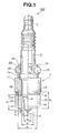
- a spark plug 300 comprises a central electrode 303 extending axially of the spark plug 300, an insulator 302 surrounding the central electrode 303 and a tubular metallic shell 301 accommodating therein the insulator 302.
- the metallic shell 301 includes a front end portion 312 provided with a male thread 312a on an outer surface thereof and a protrusion 312b on an inner surface thereof, and a hexagon head portion 313.
- the insulator 302 has a step 302a engaged with the protrusion 312b via a packing 351.
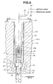
- the spark plug 100 has a clearance fit with the plug hole P1 so as to provide a clearance between the cylindrical outer surface of the front end portion 12 and the cylindrical inner surface of the front end section 36.
- a sealant 25 is provided in the clearance around the tip end portion 12 and so as to transmit the heat from the spark plug 100 to the cylinder head SH1.
- the clearance is preferably given by the following expression: 0.005 ⁇ D - d1 ⁇ 0.50 wherein D (mm) is an inner diameter of the front end section 36 and d1 (mm) is an outer diameter of the front end portion 12.
- the spark plug 100 can transmit heat efficiently to the cylinder head SH1, and can have improved heat resistance and is therefore useful in various internal combustion engines including a high-powered engine. More preferably, for attaining further improved heat resistance, the clearance is given by the following expression: 0.075 ⁇ D - d1 ⁇ 0.40, and most preferably 0.075 ⁇ D - d1 ⁇ 0.15.
- the plug bearing surface 13 and the protrusion 18 have a positional relationship given by the following expression: L ⁇ 0, and more preferably 0 ⁇ L ⁇ 6, wherein L is an axial distance (mm) from the plug bearing surface 13 to a rear edge of the protrusion 18, and at the same time, the sealant 25 is placed on at least a part 12a of the outer surface of the front end portion 12 that axially corresponds in position to the protrusion 18.
- the sealant 25 is required to have thermal properties of withstanding the service conditions (especially, high temperature conditions) of internal combustion engine.
- the sealant 25 has heat resistance of 400°C or higher.
- the sealant 25 preferably contains at least one of metal powder, alloy powder and ceramic powder each having a thermal conductivity of 20 W/m ⁇ K or higher in order to rapidly transmit heat.
- the metal, alloy and/or ceramic powders may be mixed with viscous and/or elastic material.
- Specific examples of the metal powder include copper powder, aluminum powder, molybdenum powder or the like.
- Specific examples of the alloy powder include molybdenum disulfide and the like.
- Specific examples of the ceramic powder include aluminum nitride, boron nitride and the like.
- each of the metal, alloy and ceramic powders preferably has an average particle size smaller than or equal to half of the clearance so that the sealant 25 maintains good viscosity or elasticity.
- the sealant 25 has heat resistant of about 400°C, and comprises copper powder contained in mineral oil in an amount of 40% by weight based on the total weight of the sealant 25.
- the front end portion 12 of the metallic shell 1 may be chamfered, and the front end section 36 of the plug hole P1 may be shaped to fit with the chamfered front end portion 12.
- the metallic shell 1 and the plug hole P1 may be egg-shaped, oval-shaped or polygonal-shaped.
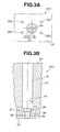
- the joint section 17 is formed in a particular position relative to the rotational position of the spark plug 100 so that the ground electrode 4 does not prevent the swirl from flowing into the spark gap g. This makes it possible to determine the position and orientation of the ground electrode 4 in the combustion chamber easily and properly.
- the sealant 25 is applied to the outer surfaces of the front end portion 12 and the key projection 19. It is not necessary to apply the sealant 25 to the whole of the outer surface of the front end portion 12, and the sealant 25 may be applied to a part of the outer surface of the front end portion 12 as described above. In this case, it is preferable to apply the sealant 25 to a front part of the outer surface of the front end portion 12 so that the sealant 25 spreads through the clearance when the spark plug 100 is being inserted in the plug hole P1.
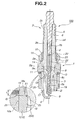
- the spark plug 100 is inserted into the plug hole P1 so that the key projection 19 is engaged in the key depression 39 and the plug bearing portion 11 and the front end portion 12 of the metal shell 1 are accommodated in the receiving section 35 and the front end section 36 of the plug hole P1, respectively.
- the ground electrode 304 is positioned so as not to interfere with the flow of swirl by the engagement between the key projection 19 and the key depression 39.
- the plug bearing surface 13 is seated on the shoulder 37 via the gasket G.
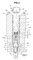
- the ignition coil unit 50 has a core coil 44, a primary winding L1, a secondary winding L2, a connection terminal 45 in the form of a coil spring, and an insulating element 46 generally made of heat-resistant rubber.
- the primary and secondary windings L1 and L2 are wound around the core coil 44, while one end of the secondary winding L2 is connected to the connection terminal though so not shown.
- the plug fixing member 41 is provided with a connector 47 connected to external devices (such as a power source and a ECU, not shown) and an ignition switch 48 accommodating therein a switching element (not shown) for controlling current supply from the power source.
- the above-structured plug fixing member 41 is set by inserting the tube portion 43 into the plug hole P1 until the front end face 43a contacts with the rear end face of the plug bearing portion 11 of the metallic shell 1.
- the connection terminal 45 electrically connects the secondary winding L2 to the terminal electrode 5 so as to supply high discharge voltage while being held against the spring tension.
- the insulating element 46 is brought into contact with the shell portion 2b of the insulator 2, thereby providing electrical insulation between the spark plug 100 and the ignition coil unit 50.
- the plug fixing member 41 is disposed so that the holes of the flange portion 42 are positioned correspondingly to the threaded holes 32a to 32d, and is then secured by screwing the bolts (including the bolts 49a and 49c) into the threaded holes 32a to 32d through the holes .
- the plug bearing portion 11 of the metallic shell 1 is pushed down with the front end face 43a of the tube portion 43, thereby sealing a gap between the plug bearing surface 13 and the shoulder 37 with the gasket G.
- the length of the tube portion 43 has been previously adjusted according to the dimensions of the spark plug 100 and the plug hole P1, so that the front end face 43 pushes the rear end face of the plug bearing portion 11 with a predetermined pressure.
- the ignition coil unit 50 can be arranged in the plug hole P1. Since a high-tension cable is not needed for electrically connecting the spark plug 100 with the ignition coil unit 50, noise reduction will result.
- the ground electrode 4 is positioned so as not to prevent swirl from flowing into the spark gap g.
- the spark plug 100 can attain high and stable ingitionability, thus being capable of igniting even a lean mixture assuredly.
Landscapes
- Chemical & Material Sciences (AREA)
- Engineering & Computer Science (AREA)
- Combustion & Propulsion (AREA)
- Spark Plugs (AREA)
Applications Claiming Priority (2)
| Application Number | Priority Date | Filing Date | Title |
|---|---|---|---|
| JP2001113632 | 2001-04-12 | ||
| JP2001113632 | 2001-04-12 |
Publications (4)
| Publication Number | Publication Date |
|---|---|
| EP1249907A2 true EP1249907A2 (de) | 2002-10-16 |
| EP1249907A3 EP1249907A3 (de) | 2006-11-02 |
| EP1249907B1 EP1249907B1 (de) | 2009-10-28 |
| EP1249907B8 EP1249907B8 (de) | 2010-02-03 |
Family
ID=18964825
Family Applications (1)
| Application Number | Title | Priority Date | Filing Date |
|---|---|---|---|
| EP02008397A Expired - Lifetime EP1249907B8 (de) | 2001-04-12 | 2002-04-12 | Befestigungsanordnung einer Zündkerze und Zündkerze dafür |
Country Status (3)
| Country | Link |
|---|---|
| US (1) | US6703770B2 (de) |
| EP (1) | EP1249907B8 (de) |
| DE (1) | DE60234144D1 (de) |
Cited By (3)
| Publication number | Priority date | Publication date | Assignee | Title |
|---|---|---|---|---|
| EP1662626A1 (de) * | 2004-11-29 | 2006-05-31 | Renault | Neues Zusammensetzungsverfahren einer Anordnung einer Zündkerze und einer Spule durch Benützung eines Einspannungsmoments mit Hilfe des Spulenkörpers |
| CN101507066B (zh) * | 2006-06-16 | 2012-07-25 | 费德罗-莫格尔公司 | 火花塞 |
| EP2187490A4 (de) * | 2007-08-01 | 2014-01-01 | Ngk Spark Plug Co | Zündkerze |
Families Citing this family (11)
| Publication number | Priority date | Publication date | Assignee | Title |
|---|---|---|---|---|
| DE60044563D1 (de) * | 1999-12-13 | 2010-07-29 | Ngk Spark Plug Co | Zündkerze |
| US6617769B2 (en) * | 2000-06-30 | 2003-09-09 | Ngk Spark Plug Co., Ltd. | Spark plug and mounting structure of the same |
| EP1560232B1 (de) | 2004-01-27 | 2012-03-14 | Robert Bosch Gmbh | Zündspulentester |
| JP2008123989A (ja) * | 2006-10-18 | 2008-05-29 | Denso Corp | 内燃機関用スパークプラグ |
| US8365710B2 (en) * | 2008-10-03 | 2013-02-05 | Federal-Mogul Ignition Company | Ignitor for air/fuel mixture and engine therewith and method of assembly thereof into a cylinder head |
| KR101630196B1 (ko) * | 2009-01-12 | 2016-06-14 | 페더럴-모굴 이그니션 컴퍼니 | 공기/연료 혼합물용 플렉시블 점화기 어셈블리 및 그 구성 방법 |
| JP6157519B2 (ja) * | 2015-01-27 | 2017-07-05 | 日本特殊陶業株式会社 | スパークプラグ |
| JP6293810B2 (ja) * | 2016-03-22 | 2018-03-14 | 日本特殊陶業株式会社 | 点火システム |
| JP7063125B2 (ja) * | 2018-06-06 | 2022-05-09 | 株式会社デンソー | 内燃機関用のスパークプラグ及び内燃機関用の点火装置 |
| JP2020119826A (ja) * | 2019-01-25 | 2020-08-06 | 日本特殊陶業株式会社 | スパークプラグの検査方法およびスパークプラグの製造方法 |
| JP7220167B2 (ja) | 2020-02-11 | 2023-02-09 | 日本特殊陶業株式会社 | スパークプラグ |
Citations (2)
| Publication number | Priority date | Publication date | Assignee | Title |
|---|---|---|---|---|
| US5186132A (en) | 1990-09-03 | 1993-02-16 | Friedrich Runge | Spark plug for an internal combustion engine |
| EP1168543A2 (de) | 2000-06-30 | 2002-01-02 | Ngk Spark Plug Co., Ltd | Funkenkerze und Einbaustruktur vom selben |
Family Cites Families (7)
| Publication number | Priority date | Publication date | Assignee | Title |
|---|---|---|---|---|
| NL81173C (de) * | 1900-01-01 | |||
| US424027A (en) * | 1890-03-25 | Igniting apparatus for gas-engines | ||
| US2693082A (en) * | 1951-04-04 | 1954-11-02 | Gen Motors Corp | Gas turbine fuel igniter |
| DE4003021A1 (de) * | 1990-02-02 | 1991-08-08 | Didier Werke Ag | Zuendanlage fuer brennkraftmaschinen |
| US5091672A (en) * | 1990-06-26 | 1992-02-25 | Allied-Signal Inc. | Shield for aligning a ground electrode of a spark plug in a cylinder head |
| JPH1064656A (ja) * | 1996-08-20 | 1998-03-06 | Ngk Spark Plug Co Ltd | 内燃機関用スパークプラグ |
| JP4445107B2 (ja) * | 2000-08-10 | 2010-04-07 | 日本特殊陶業株式会社 | コイル一体型点火プラグの取付構造およびコイル一体型点火プラグ |
-
2002
- 2002-04-11 US US10/119,716 patent/US6703770B2/en not_active Expired - Fee Related
- 2002-04-12 DE DE60234144T patent/DE60234144D1/de not_active Expired - Lifetime
- 2002-04-12 EP EP02008397A patent/EP1249907B8/de not_active Expired - Lifetime
Patent Citations (2)
| Publication number | Priority date | Publication date | Assignee | Title |
|---|---|---|---|---|
| US5186132A (en) | 1990-09-03 | 1993-02-16 | Friedrich Runge | Spark plug for an internal combustion engine |
| EP1168543A2 (de) | 2000-06-30 | 2002-01-02 | Ngk Spark Plug Co., Ltd | Funkenkerze und Einbaustruktur vom selben |
Cited By (4)
| Publication number | Priority date | Publication date | Assignee | Title |
|---|---|---|---|---|
| EP1662626A1 (de) * | 2004-11-29 | 2006-05-31 | Renault | Neues Zusammensetzungsverfahren einer Anordnung einer Zündkerze und einer Spule durch Benützung eines Einspannungsmoments mit Hilfe des Spulenkörpers |
| FR2878658A1 (fr) * | 2004-11-29 | 2006-06-02 | Renault Sas | Nouveau procede de montage d'un ensemble bougie et bobine utilisant une transmission du couple de serrage par le corps de la bobine |
| CN101507066B (zh) * | 2006-06-16 | 2012-07-25 | 费德罗-莫格尔公司 | 火花塞 |
| EP2187490A4 (de) * | 2007-08-01 | 2014-01-01 | Ngk Spark Plug Co | Zündkerze |
Also Published As
| Publication number | Publication date |
|---|---|
| EP1249907B1 (de) | 2009-10-28 |
| EP1249907A3 (de) | 2006-11-02 |
| US6703770B2 (en) | 2004-03-09 |
| US20020149308A1 (en) | 2002-10-17 |
| DE60234144D1 (de) | 2009-12-10 |
| EP1249907B8 (de) | 2010-02-03 |
Similar Documents
| Publication | Publication Date | Title |
|---|---|---|
| EP1249907B1 (de) | Befestigungsanordnung einer Zündkerze und Zündkerze dafür | |
| EP1168543B1 (de) | Funkenkerze und Einbaustruktur vom selben | |
| US6655334B2 (en) | Ignition apparatus for use in internal combustion engine | |
| KR20090118986A (ko) | 14mm 확장 스파크 플러그 | |
| EP0458375A1 (de) | Zündkerzenzusammenbau für Verbrennungsmotor | |
| US20070126330A1 (en) | Spark plug | |
| EP2690726B1 (de) | Zündkerze | |
| US8384278B2 (en) | Leadless package housing having an insulator and composition | |
| US6548945B1 (en) | Spark plug and method of manufacturing the same | |
| US8531094B2 (en) | Spark plug having self-cleaning of carbon deposits | |
| US20240204488A1 (en) | Spark plug and method for producing a spark plug | |
| US6819030B2 (en) | Spark plug | |
| EP0554045B1 (de) | Zündkerze | |
| JP4068381B2 (ja) | スパークプラグの取付構造 | |
| US7243643B2 (en) | Ignition device for internal combustion engine | |
| US8373337B2 (en) | Spark plug having a reduced physical volume | |
| US20200412104A1 (en) | Spark plug | |
| JP4480294B2 (ja) | スパークプラグの取付構造及びスパークプラグ | |
| US20100007257A1 (en) | Spark Plug | |
| JP7267231B2 (ja) | スパークプラグ | |
| JP2000003777A (ja) | 点火プラグおよび点火プラグ組立体 | |
| JP2000133411A (ja) | コイル一体型点火プラグ | |
| CA3153780C (en) | Spark plug and method for producing a spark plug | |
| JP2002054543A (ja) | コイル一体型点火プラグの取付構造およびコイル一体型点火プラグ | |
| KR100534682B1 (ko) | 점화 플러그 |
Legal Events
| Date | Code | Title | Description |
|---|---|---|---|
| PUAI | Public reference made under article 153(3) epc to a published international application that has entered the european phase |
Free format text: ORIGINAL CODE: 0009012 |
|
| AK | Designated contracting states |
Kind code of ref document: A2 Designated state(s): AT BE CH CY DE DK ES FI FR GB GR IE IT LI LU MC NL PT SE TR |
|
| AX | Request for extension of the european patent |
Free format text: AL;LT;LV;MK;RO;SI |
|
| PUAL | Search report despatched |
Free format text: ORIGINAL CODE: 0009013 |
|
| AK | Designated contracting states |
Kind code of ref document: A3 Designated state(s): AT BE CH CY DE DK ES FI FR GB GR IE IT LI LU MC NL PT SE TR |
|
| AX | Request for extension of the european patent |
Extension state: AL LT LV MK RO SI |
|
| 17P | Request for examination filed |
Effective date: 20061214 |
|
| 17Q | First examination report despatched |
Effective date: 20070608 |
|
| AKX | Designation fees paid |
Designated state(s): DE FR |
|
| GRAP | Despatch of communication of intention to grant a patent |
Free format text: ORIGINAL CODE: EPIDOSNIGR1 |
|
| GRAS | Grant fee paid |
Free format text: ORIGINAL CODE: EPIDOSNIGR3 |
|
| GRAA | (expected) grant |
Free format text: ORIGINAL CODE: 0009210 |
|
| AK | Designated contracting states |
Kind code of ref document: B1 Designated state(s): DE FR |
|
| REF | Corresponds to: |
Ref document number: 60234144 Country of ref document: DE Date of ref document: 20091210 Kind code of ref document: P |
|
| RIN2 | Information on inventor provided after grant (corrected) |
Inventor name: IWATA, KAZUYA Inventor name: SUZUKI, TAKAHIRO Inventor name: SUZUKI, AKIRA Inventor name: KAWAMURA, KAZUMI |
|
| PLBE | No opposition filed within time limit |
Free format text: ORIGINAL CODE: 0009261 |
|
| STAA | Information on the status of an ep patent application or granted ep patent |
Free format text: STATUS: NO OPPOSITION FILED WITHIN TIME LIMIT |
|
| 26N | No opposition filed |
Effective date: 20100729 |
|
| REG | Reference to a national code |
Ref country code: FR Ref legal event code: PLFP Year of fee payment: 14 |
|
| PGFP | Annual fee paid to national office [announced via postgrant information from national office to epo] |
Ref country code: DE Payment date: 20150408 Year of fee payment: 14 |
|
| PGFP | Annual fee paid to national office [announced via postgrant information from national office to epo] |
Ref country code: FR Payment date: 20150408 Year of fee payment: 14 |
|
| REG | Reference to a national code |
Ref country code: DE Ref legal event code: R119 Ref document number: 60234144 Country of ref document: DE |
|
| REG | Reference to a national code |
Ref country code: FR Ref legal event code: ST Effective date: 20161230 |
|
| PG25 | Lapsed in a contracting state [announced via postgrant information from national office to epo] |
Ref country code: FR Free format text: LAPSE BECAUSE OF NON-PAYMENT OF DUE FEES Effective date: 20160502 Ref country code: DE Free format text: LAPSE BECAUSE OF NON-PAYMENT OF DUE FEES Effective date: 20161101 |