EP1250968A1 - Pressvorrichtung - Google Patents
Pressvorrichtung Download PDFInfo
- Publication number
- EP1250968A1 EP1250968A1 EP01114163A EP01114163A EP1250968A1 EP 1250968 A1 EP1250968 A1 EP 1250968A1 EP 01114163 A EP01114163 A EP 01114163A EP 01114163 A EP01114163 A EP 01114163A EP 1250968 A1 EP1250968 A1 EP 1250968A1
- Authority
- EP
- European Patent Office
- Prior art keywords
- slide cam
- pressing
- cam
- base
- slide
- Prior art date
- Legal status (The legal status is an assumption and is not a legal conclusion. Google has not performed a legal analysis and makes no representation as to the accuracy of the status listed.)
- Withdrawn
Links
Images




Classifications
-
- B—PERFORMING OPERATIONS; TRANSPORTING
- B30—PRESSES
- B30B—PRESSES IN GENERAL
- B30B15/00—Details of, or accessories for, presses; Auxiliary measures in connection with pressing
-
- B—PERFORMING OPERATIONS; TRANSPORTING
- B21—MECHANICAL METAL-WORKING WITHOUT ESSENTIALLY REMOVING MATERIAL; PUNCHING METAL
- B21D—WORKING OR PROCESSING OF SHEET METAL OR METAL TUBES, RODS OR PROFILES WITHOUT ESSENTIALLY REMOVING MATERIAL; PUNCHING METAL
- B21D5/00—Bending sheet metal along straight lines, e.g. to form simple curves
- B21D5/04—Bending sheet metal along straight lines, e.g. to form simple curves on brakes making use of clamping means on one side of the work
Definitions
- the present invention relates to a pressing apparatus, and particularly to a pressing apparatus exerting a pressing force only near the lower dead center of the pressing stroke where the pressing force is mostly needed.
- the slide cam is urged by a pressing-urge provider, which is generally provided by a coil spring.
- a pressing-urge provider which is generally provided by a coil spring.
- an initial spring pressure must also be set at a high level.
- the slide cam, a slide cam base and a sliding portion of a driven cam are subject to abnormal wear and seizure.
- Another problem is that during a preparatory step before manufacture, a few design changes are usually made to the pressing apparatus. On such occasions for example, it is required that the slide cam, the slide cam base, the driven cam and so on can be disassembled and reassembled easily, with the pressing apparatus staying installed to the pressing machine.
- the present invention provides a pressing apparatus as defined in claim 1.
- Preferred embodiments are defined in the dependent claims.
- the present embodiment is a pressing apparatus for bending a work.
- a lower die 82 has a lower base plate 1 provided with a supporting member 2 fixed by one or more bolts 3 for positioning a work W.
- a driven cam 4 having an upper surface slanted to become lower toward the supporting member 2, i.e. having a rightward rising slope as viewed in the figure, is fixed by one or more bolts 5.
- the slanted surface 6 of the driven cam 4 is provided with a ridge-shaped guide 7.
- the ridge-shaped guide 7 has an upper surface provided with a wear plate 9 fixed by one or more bolts 10. Further, the slanted surface 6 of the driven cam 4 is provided with a wear plate 11 fixed by one or more bolts 12.
- a slide cam 19 is generally wedge-shaped, having a lower surface provided with a V groove 16 and a wear plate 17 fixed by one or more bolts 18.
- the V groove is provided with a wear plate 9 contacted with the driven cam 4.
- the wear plate 17 is contacted with the wear plate 11 of the driven cam 4. With this arrangement, the slide cam 19 is slidably mounted on the driven cam 4.
- a slide cam base 21 has a surface oppositely slanted to the driven cam 4, or more specifically has a rightward falling slope as viewed in the figure 1, and is fixed to an upper base plate 22 of an upper die 81 by one or more bolts 23.
- the slide cam base 21 has a lower end portion provided with rightward falling guideposts 24, to which the slide cam 19 is slidably installed. Further, the slide cam 19 is urged by a gas spring 25 which serves as a retracting-urge provider, built in the slide cam base 21 in a rightward falling direction as viewed in Fig. 4.
- the guideposts 24 are installed on two walls 28, 29 of the slide cam base 21.
- the guideposts 24 are each fitted via bushings 30, 31 into bores 42 provided in a guidepost support 41 in an upper portion of the slide cam 19.
- the bushings 30, 31 are coaxially fitted into the respective bores.
- Each of the guideposts 24 has a diametrically smaller end portion 32 inserted into a fitting bore 33 of the wall 28.
- a nut 83 is threaded to the protruding tip of the diametrically smaller end 32, while the other end portion 34 is fitted into a fitting bore 35 of the wall 29.
- a circular circumference and circular bore can be machined highly accurately as compared to prismatic or other shapes because of the circular nature.
- the guidepost 24 is made to have a circular section, and the bushings 30, 31 and the fitting hole 33 are shaped into circular holes, so that machining can be performed highly accurately. Further, since the guidepost 24 having a circular circumferential surface is in a tight-fit relationship with circular bores of the bushings 30, 31, a highly accurate radial fitting from the center of axis can be maintained over the entire 360-degree circumference.
- the guideposts may be solid or hollow as long as they have a circular section. However, in consideration of strength, a solid guidepost is preferable.
- the slide cam 19 must be removed from the slide cam base 21 for the purpose of making maintenance work on the slide cam 19, the driven cam 4, the slide cam base 21 and so on.
- the slide cam 19 there is no need for removing many bolts as in the prior art. Instead, by simply removing the nut 83 from the end of the diametrically smaller end 32, the guidepost 24 can be easily pulled out.
- the slide cam 19 is provided in the slide cam base 21 via the guideposts 24 and the gas springs 25.
- the lower portion of the slide cam base 21 is provided with four of the guideposts 24, with a space in between serving as guide grooves 40.
- the slide cam 19 has an upper portion provided with the rightward rising guidepost supports 41.
- the guidepost supports 41 are movable within the guide grooves 40.
- the guidepost supports 41 are formed with the rightward falling insertion bores 42. These insertion bores 42 are fitted by coaxial bushings 30, 31, and the guideposts 24 are fitted into these bushings 30, 31.
- the gas spring 25 is disposed on a slant, with rightward end being arranged lower than the leftward end and a rod 44 contacted with the wall 28.
- the rod 44 which provides the gas spring 25 together with a cylinder 43, can extend and retract.
- the gas spring 25 has a base end contacted with a mounting plug 84 threaded to the guidepost support 41 formed at a lower region of an upper portion of the slide cam 19.
- the guidepost support 41 of the slide cam 19 has an upper surface provided with a wear plate 87 fixed by one or more bolts 88 (see Fig. 1). The wear plate 85 and the wear plate 87 contact and slide along each other.
- the slide cam 19 is generally wedge-shaped, sandwiched between the driven cam 4 and the slide cam base 21, and thereby pushed to move toward the work W placed on the supporting member 2, to press the work W.
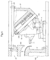
- Fig. 1 and 4 show a state in which the pressing apparatus is at its lower dead center.
- the slide cam 19 approaches the supporting member 2, and the figure shows the slide cam at a left end of its stroke, with rod 44 of the gas spring 25 in its fully retracted state.
- an urging force from the gas spring 25 acts on the slide cam 19, and the rod 44 begins to extend.
- the rod 44 is fully extended at the upper dead center, i.e. the state shown in Fig. 8 (The fully extended rod 44 is not illustrated).
- the cylinder 43 of the gas spring 25 is charged with a gas of a high pressure, at 150 kgf/cm 2 for example, adapted and depending from the particular application, and provides a generally constant output of 150 kgf/cm 2 for example, over an entire stroke of the rod 44 regardless of the position of the rod 44 extending out of or retracting into the cylinder 43.
- a gas of a high pressure at 150 kgf/cm 2 for example, adapted and depending from the particular application, and provides a generally constant output of 150 kgf/cm 2 for example, over an entire stroke of the rod 44 regardless of the position of the rod 44 extending out of or retracting into the cylinder 43.
- This is made possible by two tanks incorporated in the cylinder 43. When the rod 44 is retracted to pressurize one of the tanks, the high pressure gas in this tank flows out into the other tank, thereby maintaining a generally constant output over the entire stroke of the rod (although the output may become slightly larger under compression).
- the gas spring 25 can provide a high and substantially constant output over its entire stroke, making it possible to reliably retract the slide cam 19 and being safe.
- gas spring 25 can move the slide cam 19 for a long distance, making it possible to press a large work of sheet metal into such a product as automobile side panel.
- the slide cam base 21 and the slide cam 19 respectively have sliding surfaces provided with wear plates 87, 85 respectively.
- the wear plate 87 is fixed by one or more bolts 88 to the slide cam base 21, whereas the wear plate 85 is fixed by one or more bolts 86 to the slide cam 19.
- the surface pressure used is 50 to 60 kgf/cm 2
- only one of the slide cam base and the slide cam is provided with a wear plate.
- each of the slide cam base and the slide cam is provided with a wear plate and only worn-out wear plates must be replaced, so that the pressing apparatus can be used on a large pressing machine capable of exerting surface pressures of up to 150 kgf/cm 2 .
- the present embodiment is described as an apparatus for bending operation.
- a bending member 71 is fixed by one or more bolts 72 to the slide cam 19, at a location facing the supporting member 2 which supports the work W.
- the work W is placed on the supporting member 2, and then the upper die 81 is lowered.
- the state shown in Fig. 8 is when the pressing apparatus is at its upper dead center, where the slide cam 19 is slidably provided on the guideposts 24 of the slide cam base 21 which are attached to the upper base plate 22 of the upper die 81, and the slide cam 19 is under an urge from the gas spring 25 and is contacted with the wall 29.
- the wear plate 17 of the slide cam 19 and the wear plate 9 of the V groove 16 make contact with the wear plate 11 and the ridge-shaped guide 7 of the driven cam 4.
- the slide cam 19 sandwiched by the driven cam 4 and the slide cam base 21 presses the work W while a pad 89 presses the work onto the supporting member 2 from above.
- the slide cam 19 moves forward to the work W, and the work W is bent by the cooperation of the supporting member 2 and the bending member 71.
- the members indicated by numerals 90 and 91 are a suspending bolt and a coil spring respectively for the pad 89.
- Fig. 6 is a stroke diagram of the bending operation with an example of a pressing apparatus of the present invention.
- a vertical pressing stroke of this pressing apparatus is 84.59 mm.
- a travel distance of the slide cam 19 on the guideposts 24 is 110 mm, and a travel distance of the slide cam 19 on the driven cam 4 is 78.08 mm.
- the slide cam 19 is supported by the four guideposts 24, and use is made of three gas springs serving as retracting-urge providers and a total of six coil springs 91 serving as pressing-urge providers.
- Fig. 4 shows the pressing apparatus at its lower dead center, in which the rod 44 of the gas spring 25 is fully retracted.
- the gas springs 25 are each contacted with the mounting plug 84.
- a through hole 93 is provided in the wall 29 facing each of the mounting plugs 84, whereas a hexagonal hole 94 is provided in the outward surface of each mounting plug 84 as a receptacle for a wrench or other suitable tool.
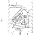
- Fig. 5 The state in which the slide cam 19 is under the urge from the coil spring 91 is shown in Fig. 5.
- the pressing apparatus is at its lower dead center, at which the coil spring 91 is fully compressed.
- a through hole 96 is provided in the wall 29 facing each of the mounting plugs 95, whereas a hexagonal hole 97 is provided in the outward surface of each mounting plug 95 as a receptacle for a wrench or other suitable tool.
- the coil spring 91 contacting the mounting plug 95 is attached around the positioning pin 98.
- the positioning pin 98 is slidably inserted into a bushing 50 press-fitted to the guidepost support 41 of the slide cam 19.
- the positioning pin 98 has an upper end surface contacted with the wall 28 of the slide cam base 21.
- the coil spring 91 has an end contacted with the mounting plug 95, and the other end contacted with a flange 51 provided at an intermediate portion of the positioning pin 98.
- the coil spring 91 is fully compressed in the figure, exerting the greatest spring pressure.
- the coil spring 91 initially is fully extended, with the flange 51 of the positioning pin 98 contacted with a bore bottom 52, and its spring pressure is small. However, the spring pressure becomes large near the lower dead center of the pressing stroke. A setting is made in such a way that a large pressing force necessary for bending operation near the ending portion of the pressing stroke is exerted. It should be noted here that when the coil spring 91 is compressed, its spring force acts rightward as in the figure, and the reaction thereof slides the slide cam 19 leftward.
- Another coil spring 91 is provided between the slide cam 19 and the driven can 4.
- a positioning pin 99 is threaded into an upright wall 53 in an upper surface of the driven cam 4.
- the coil spring 91 is attached around this pin, which penetrates an L-shaped pressure receiving member 54 fixed to a lower surface of the slide cam 19.
- the coil spring 91 is compressed between the wall 53 and the pressure receiving member 54, and its spring pressure is set in such a way that a large pressing force necessary for effecting a bending operation is exerted near the end portion of the pressing stroke.
- four coil springs 91 are used between the slide cam 19 and the slide cam base 21, and two coil springs 91 are used between the slide cam 19 and the driven cam 4.
- the coil spring may be used only between the slide cam and the slide cam base, or only between the slide cam and the driven cam.
- the gas spring 25 and the coil spring 91 used in the present embodiment will be described by using a spring diagram shown in Fig. 7.
- the gas spring 25 used in the present embodiment has a main body of a length of 300 mm when fully extended, with an allowable stroke of 125 mm (this relationship is not shown in Fig. 7). Of this stroke, a 110 mm stroke is utilized (this relationship is not shown in Fig. 7), with the remaining 15 mm stroke not being used (this relationship is not shown in Fig. 7).
- the coil spring 91 has a total length of 152 mm. Of this length, 30 mm is used and the remaining 122 mm is not used. Of the 30 mm, 5 mm is used for initial pressurizing and the remaining 25 mm stroke is used for an output used for the bending operation.
- an output from the gas spring 25 is 11700 N (Newton: 1 kgf ⁇ 9.8 N). From here, at a point further down the stroke by 25 mm, an output from the gas spring 25 is 15400 N. The initial pressure from the coil spring 91 compressed by 5 mm is 5040 N. Thus, a total output combined with the 11700 N output from the gas spring 25 is 16740 N. On the other hand, when at the point further down the stroke by 25 mm, an output from the coil spring 91 is 30240 N. Thus, a total output combined with the 15400 N output from the gas spring 25 is 45640 N.
- a total pressing stroke of this pressing apparatus is 84.59 mm as shown in Fig. 6.
- the output is increased from 16740 N to 45640 N in an about 25 mm portion near the end of the pressing stroke.
- a large pressing force necessary for bending operation is outputted near the end portion of the pressing stroke, thereby achieving a high quality bending.
- the gas spring 25 can exert a large force to retract the slide cam 19 near the end portion of the pressing stroke.
- the slide cam 19 is provided with a return plate 59. Therefore, if the slide cam 19 is not retracted for some reason, the return plate 59 engages with the driven cam 4, thereby forcing the slide cam 19 to retract.
- slide cam base 21, the slide cam 19 and the driven can 4 may be standardized so that the pressing apparatus can be readily adapted to works of a variety of sizes.
- the slide cam base 21 is provided in the upper die 81 and the driven cam 4 is provided in the lower die 82.
- the slide cam base 21 may be provided in the lower die 82 and the driven cam 4 may be provided in the upper die 81.
- This case may sometimes be regarded as safer for the operation, because the slide cam 19 is not hanging down from the upper die 81 but is mounted on the lower die 82.
- the present invention encompasses not only the case in which the slide cam 19 is supported in the upper die 81 but also the case in which the slide cam 19 is disposed in the lower die 82.
- an urging force for the slide cam to press is provided only when necessary, and elsewhere this pressing-urge is held as small as possible, whereby abnormal wear and seizure of the slide cam, slide cam base and the sliding portion of the driven cam are prevented. Further, the present invention enables to provide a large retracting force for the slide cam near a lower dead center of a pressing stroke.
- the setting of the cam according to the pressing apparatus provided by the present invention also clears an interference problem in a transfer pressing.
Landscapes
- Engineering & Computer Science (AREA)
- Mechanical Engineering (AREA)
- Bending Of Plates, Rods, And Pipes (AREA)
- Mounting, Exchange, And Manufacturing Of Dies (AREA)
- Press Drives And Press Lines (AREA)
- Folding Of Thin Sheet-Like Materials, Special Discharging Devices, And Others (AREA)
Applications Claiming Priority (2)
| Application Number | Priority Date | Filing Date | Title |
|---|---|---|---|
| JP2001118961A JP2002316223A (ja) | 2001-04-18 | 2001-04-18 | プレス装置 |
| JP2001118961 | 2001-04-18 |
Publications (1)
| Publication Number | Publication Date |
|---|---|
| EP1250968A1 true EP1250968A1 (de) | 2002-10-23 |
Family
ID=18969257
Family Applications (1)
| Application Number | Title | Priority Date | Filing Date |
|---|---|---|---|
| EP01114163A Withdrawn EP1250968A1 (de) | 2001-04-18 | 2001-06-11 | Pressvorrichtung |
Country Status (7)
| Country | Link |
|---|---|
| US (1) | US6619095B2 (de) |
| EP (1) | EP1250968A1 (de) |
| JP (1) | JP2002316223A (de) |
| KR (1) | KR20020081021A (de) |
| BR (1) | BR0103095A (de) |
| CA (1) | CA2350699A1 (de) |
| TW (1) | TW514567B (de) |
Cited By (1)
| Publication number | Priority date | Publication date | Assignee | Title |
|---|---|---|---|---|
| EP1584385A1 (de) * | 2004-04-06 | 2005-10-12 | Trumpf Maschinen Austria GmbH & CO. KG. | Biegewerkzeug zum Biegen von Werkstücken, insbesondere von Blechen sowie Biegemaschine mit einem derartigen Biegewerkzeug |
Families Citing this family (22)
| Publication number | Priority date | Publication date | Assignee | Title |
|---|---|---|---|---|
| ATE337165T1 (de) * | 2000-10-13 | 2006-09-15 | Harald Weigelt | Keiltrieb |
| JP3540308B2 (ja) * | 2002-05-16 | 2004-07-07 | ユミックス株式会社 | スライドカム型 |
| US7258030B2 (en) * | 2003-01-21 | 2007-08-21 | Syron Engineering & Manufacturing, Llc | Failsafe element for rotary cam unit used in a flanged die |
| JP4483192B2 (ja) * | 2003-03-31 | 2010-06-16 | オイレス工業株式会社 | ホルダユニット及びそのホルダユニットを具備したヘミング加工装置 |
| JP4539087B2 (ja) * | 2003-12-02 | 2010-09-08 | オイレス工業株式会社 | プレス金型用カム |
| US7523634B2 (en) * | 2004-08-24 | 2009-04-28 | Helical Cam, Llc. | Forming die having filler cam assembly |
| US7237423B1 (en) * | 2004-11-12 | 2007-07-03 | Miller Tool And Die Company Inc. | Apparatus for stretch forming blanks |
| CN100486727C (zh) * | 2004-11-18 | 2009-05-13 | 丹利·耶姆有限公司 | 装配压床的靠模 |
| US7080542B2 (en) * | 2004-11-18 | 2006-07-25 | Danly Iem, Llc | Press mounted cam and method of manufacture |
| US7191635B2 (en) * | 2004-11-18 | 2007-03-20 | Danly Iem, Llc | Press mounted cam |
| DE102005029140B4 (de) * | 2005-06-23 | 2008-04-03 | Elke Weigelt | Werkzeugbefestigungseinrichtung für einen Keiltrieb |
| US8171821B2 (en) | 2006-09-28 | 2012-05-08 | Helical Cam, Llc | Corner cam assembly |
| US8516874B2 (en) * | 2007-12-27 | 2013-08-27 | Toyota Motor Engineering & Manufacturing North America, Inc. | Pillar for motor vehicle and tool for making the same |
| US7735907B2 (en) * | 2007-12-27 | 2010-06-15 | Toyota Motor Engineering & Manufacturing North America, Inc. | Pillar for motor vehicle and tool for making the same |
| US20100050729A1 (en) * | 2008-09-01 | 2010-03-04 | Rahul Kulkarni | Die assembly for use in an apparatus for forming a workpiece |
| JP2011140048A (ja) * | 2010-01-08 | 2011-07-21 | Sankyo Oilless Industry Inc | カム装置 |
| JP4900499B2 (ja) * | 2010-04-26 | 2012-03-21 | オイレス工業株式会社 | プレス金型用カム |
| JP5903479B2 (ja) * | 2014-11-14 | 2016-04-13 | 三協オイルレス工業株式会社 | カム装置 |
| JP5903480B2 (ja) * | 2014-11-14 | 2016-04-13 | 三協オイルレス工業株式会社 | カム装置のグループ化方法 |
| JP6126670B2 (ja) * | 2015-11-26 | 2017-05-10 | 三協オイルレス工業株式会社 | カム装置のグループ化方法 |
| CN106513509B (zh) * | 2016-10-27 | 2018-05-04 | 安徽江淮汽车集团股份有限公司 | 一种翻边模具 |
| DE102018111366B4 (de) * | 2018-05-14 | 2024-03-07 | F I B R O Gmbh | Keiltrieb mit justierbarer Führungsvorrichtung |
Citations (4)
| Publication number | Priority date | Publication date | Assignee | Title |
|---|---|---|---|---|
| JPS617024A (ja) * | 1985-06-08 | 1986-01-13 | Takatsu Seisakusho:Kk | 自動車のフロントピラー等の製造方法およびその装置 |
| EP0699489A1 (de) * | 1993-06-25 | 1996-03-06 | UMIX Co., Ltd. | Verfahren zum Formen von dünnem Blech und Formgesenk |
| US5711180A (en) * | 1994-12-27 | 1998-01-27 | Oiles Corporation | Pressing cam die |
| EP1063030A2 (de) * | 1999-06-25 | 2000-12-27 | Umix Co., Ltd. | Pressvorrichtung |
Family Cites Families (11)
| Publication number | Priority date | Publication date | Assignee | Title |
|---|---|---|---|---|
| JPS56165524A (en) * | 1980-05-26 | 1981-12-19 | Nissan Motor Co Ltd | Press forming apparatus for channel |
| JPS5930327U (ja) * | 1982-08-16 | 1984-02-25 | マツダ株式会社 | プレスワ−クの縁切り装置 |
| JPS61140250U (de) * | 1985-02-21 | 1986-08-30 | ||
| EP1047511B1 (de) * | 1997-09-18 | 2002-07-31 | Cosma International Inc. | Streck- und ziehwerkzeug und zugehöriges verfahren |
| JP2880490B1 (ja) * | 1997-11-14 | 1999-04-12 | ユミックス株式会社 | プレス装置 |
| JP3069083B2 (ja) * | 1998-11-11 | 2000-07-24 | ユミックス株式会社 | プレス装置 |
| JP4277395B2 (ja) * | 1998-11-27 | 2009-06-10 | オイレス工業株式会社 | カム装置並びにそれに用いられるカムスライド支持部材及びカムドライバ部材 |
| JP2001047156A (ja) * | 1999-08-05 | 2001-02-20 | Honda Motor Co Ltd | プレス装置 |
| JP3370628B2 (ja) * | 1999-11-15 | 2003-01-27 | ユミックス株式会社 | 負角成形型 |
| JP2001137947A (ja) * | 1999-11-15 | 2001-05-22 | Umix Kk | プレス金型の付勢装置 |
| JP4604334B2 (ja) * | 2000-10-31 | 2011-01-05 | オイレス工業株式会社 | プレス金型用カム |
-
2001
- 2001-04-18 JP JP2001118961A patent/JP2002316223A/ja active Pending
- 2001-05-18 TW TW090111881A patent/TW514567B/zh not_active IP Right Cessation
- 2001-05-30 KR KR1020010029929A patent/KR20020081021A/ko not_active Withdrawn
- 2001-06-04 BR BR0103095-7A patent/BR0103095A/pt not_active IP Right Cessation
- 2001-06-11 EP EP01114163A patent/EP1250968A1/de not_active Withdrawn
- 2001-06-15 CA CA002350699A patent/CA2350699A1/en not_active Abandoned
- 2001-07-11 US US09/901,625 patent/US6619095B2/en not_active Expired - Fee Related
Patent Citations (4)
| Publication number | Priority date | Publication date | Assignee | Title |
|---|---|---|---|---|
| JPS617024A (ja) * | 1985-06-08 | 1986-01-13 | Takatsu Seisakusho:Kk | 自動車のフロントピラー等の製造方法およびその装置 |
| EP0699489A1 (de) * | 1993-06-25 | 1996-03-06 | UMIX Co., Ltd. | Verfahren zum Formen von dünnem Blech und Formgesenk |
| US5711180A (en) * | 1994-12-27 | 1998-01-27 | Oiles Corporation | Pressing cam die |
| EP1063030A2 (de) * | 1999-06-25 | 2000-12-27 | Umix Co., Ltd. | Pressvorrichtung |
Non-Patent Citations (1)
| Title |
|---|
| PATENT ABSTRACTS OF JAPAN vol. 010, no. 153 (M - 484) 3 June 1986 (1986-06-03) * |
Cited By (1)
| Publication number | Priority date | Publication date | Assignee | Title |
|---|---|---|---|---|
| EP1584385A1 (de) * | 2004-04-06 | 2005-10-12 | Trumpf Maschinen Austria GmbH & CO. KG. | Biegewerkzeug zum Biegen von Werkstücken, insbesondere von Blechen sowie Biegemaschine mit einem derartigen Biegewerkzeug |
Also Published As
| Publication number | Publication date |
|---|---|
| US6619095B2 (en) | 2003-09-16 |
| KR20020081021A (ko) | 2002-10-26 |
| BR0103095A (pt) | 2002-12-17 |
| US20020152789A1 (en) | 2002-10-24 |
| TW514567B (en) | 2002-12-21 |
| CA2350699A1 (en) | 2002-10-18 |
| JP2002316223A (ja) | 2002-10-29 |
Similar Documents
| Publication | Publication Date | Title |
|---|---|---|
| EP1250968A1 (de) | Pressvorrichtung | |
| JP2880490B1 (ja) | プレス装置 | |
| EP2983844B1 (de) | Stempelvorrichtung | |
| US6332604B1 (en) | Clamping and positioning mechanism for the inclined axis of two-axes rotary tables | |
| EP1068909B1 (de) | Bodenherstellung | |
| CN210435661U (zh) | 双压头切换多功能伺服压机 | |
| US5715721A (en) | Floating forming die | |
| US12350729B2 (en) | Stamping dies and guided retainer devices for use in same | |
| JP2004141883A (ja) | 複動式鍛造成形方法およびその装置 | |
| US4843863A (en) | Container body maker die | |
| CN112636126B (zh) | 压接钳设备、压接机及用于建立压接连接的方法 | |
| US7398584B2 (en) | Press fitting tool | |
| CN215037070U (zh) | 一种通用销钉装配销套 | |
| CN205184205U (zh) | 一种自动对正压装装置 | |
| CN217700958U (zh) | 一种全尺寸自定位涨紧头 | |
| CN215699902U (zh) | 自适应可调支撑球锁快速压紧装置 | |
| CN212792717U (zh) | 铝合金拉伸成型模具 | |
| JPH08206753A (ja) | プレス加工用フライングプレスユニット | |
| CN216000361U (zh) | 一种连杆的柔性压套机构 | |
| CN217530628U (zh) | 一种重力避空定位机构 | |
| CN220554976U (zh) | 一种金属衬套压装装置 | |
| CN115847344B (zh) | 一种推力杆橡胶衬套压装压头以及压装装置 | |
| CN219768050U (zh) | 一种壳体的定位治具 | |
| CN215786489U (zh) | 一种热模锻用圆形模具模 | |
| CN211387031U (zh) | 一种销轴钻孔加工用定位装置 |
Legal Events
| Date | Code | Title | Description |
|---|---|---|---|
| PUAI | Public reference made under article 153(3) epc to a published international application that has entered the european phase |
Free format text: ORIGINAL CODE: 0009012 |
|
| AK | Designated contracting states |
Kind code of ref document: A1 Designated state(s): AT BE CH CY DE DK ES FI FR GB GR IE IT LI LU MC NL PT SE TR |
|
| AX | Request for extension of the european patent |
Free format text: AL;LT;LV;MK;RO;SI |
|
| 17P | Request for examination filed |
Effective date: 20030414 |
|
| AKX | Designation fees paid |
Designated state(s): DE ES FR GB IT SE |
|
| GRAP | Despatch of communication of intention to grant a patent |
Free format text: ORIGINAL CODE: EPIDOSNIGR1 |
|
| STAA | Information on the status of an ep patent application or granted ep patent |
Free format text: STATUS: THE APPLICATION IS DEEMED TO BE WITHDRAWN |
|
| 18D | Application deemed to be withdrawn |
Effective date: 20040513 |