EP1253079A2 - Luftfrachttransportsystem - Google Patents
Luftfrachttransportsystem Download PDFInfo
- Publication number
- EP1253079A2 EP1253079A2 EP02008849A EP02008849A EP1253079A2 EP 1253079 A2 EP1253079 A2 EP 1253079A2 EP 02008849 A EP02008849 A EP 02008849A EP 02008849 A EP02008849 A EP 02008849A EP 1253079 A2 EP1253079 A2 EP 1253079A2
- Authority
- EP
- European Patent Office
- Prior art keywords
- air cargo
- cargo
- aircraft
- air
- underground
- Prior art date
- Legal status (The legal status is an assumption and is not a legal conclusion. Google has not performed a legal analysis and makes no representation as to the accuracy of the status listed.)
- Granted
Links
Images


Classifications
-
- B—PERFORMING OPERATIONS; TRANSPORTING
- B64—AIRCRAFT; AVIATION; COSMONAUTICS
- B64F—GROUND OR AIRCRAFT-CARRIER-DECK INSTALLATIONS SPECIALLY ADAPTED FOR USE IN CONNECTION WITH AIRCRAFT; DESIGNING, MANUFACTURING, ASSEMBLING, CLEANING, MAINTAINING OR REPAIRING AIRCRAFT, NOT OTHERWISE PROVIDED FOR; HANDLING, TRANSPORTING, TESTING OR INSPECTING AIRCRAFT COMPONENTS, NOT OTHERWISE PROVIDED FOR
- B64F1/00—Ground or aircraft-carrier-deck installations
- B64F1/36—Other airport installations
- B64F1/368—Arrangements or installations for routing, distributing or loading baggage
-
- B—PERFORMING OPERATIONS; TRANSPORTING
- B64—AIRCRAFT; AVIATION; COSMONAUTICS
- B64F—GROUND OR AIRCRAFT-CARRIER-DECK INSTALLATIONS SPECIALLY ADAPTED FOR USE IN CONNECTION WITH AIRCRAFT; DESIGNING, MANUFACTURING, ASSEMBLING, CLEANING, MAINTAINING OR REPAIRING AIRCRAFT, NOT OTHERWISE PROVIDED FOR; HANDLING, TRANSPORTING, TESTING OR INSPECTING AIRCRAFT COMPONENTS, NOT OTHERWISE PROVIDED FOR
- B64F1/00—Ground or aircraft-carrier-deck installations
-
- B—PERFORMING OPERATIONS; TRANSPORTING
- B64—AIRCRAFT; AVIATION; COSMONAUTICS
- B64F—GROUND OR AIRCRAFT-CARRIER-DECK INSTALLATIONS SPECIALLY ADAPTED FOR USE IN CONNECTION WITH AIRCRAFT; DESIGNING, MANUFACTURING, ASSEMBLING, CLEANING, MAINTAINING OR REPAIRING AIRCRAFT, NOT OTHERWISE PROVIDED FOR; HANDLING, TRANSPORTING, TESTING OR INSPECTING AIRCRAFT COMPONENTS, NOT OTHERWISE PROVIDED FOR
- B64F1/00—Ground or aircraft-carrier-deck installations
- B64F1/30—Ground or aircraft-carrier-deck installations for embarking or disembarking passengers
- B64F1/305—Bridges extending between terminal building and aircraft, e.g. telescopic, vertically adjustable
- B64F1/3055—Bridges extending between terminal building and aircraft, e.g. telescopic, vertically adjustable with hinged head interface between aircraft and passenger bridge
-
- B—PERFORMING OPERATIONS; TRANSPORTING
- B64—AIRCRAFT; AVIATION; COSMONAUTICS
- B64F—GROUND OR AIRCRAFT-CARRIER-DECK INSTALLATIONS SPECIALLY ADAPTED FOR USE IN CONNECTION WITH AIRCRAFT; DESIGNING, MANUFACTURING, ASSEMBLING, CLEANING, MAINTAINING OR REPAIRING AIRCRAFT, NOT OTHERWISE PROVIDED FOR; HANDLING, TRANSPORTING, TESTING OR INSPECTING AIRCRAFT COMPONENTS, NOT OTHERWISE PROVIDED FOR
- B64F1/00—Ground or aircraft-carrier-deck installations
- B64F1/32—Ground or aircraft-carrier-deck installations for handling freight
- B64F1/324—Luggage loaders specially adapted for loading individual luggage items into or out of the aircraft
Definitions
- the present invention relates to an air cargo transport system, which transports the air cargo to the cargo holding area of the airport terminal building and aircraft parked on the tarmac parking area.
- aircraft are normally equipped with multiple doors for loading cargo, for example, as shown in Figure 7, the main door 70 in the center of the fuselage, the bulk door 71 in the rear of the fuselage, the lower door 72 in the front of the fuselage, and the nose door 73 at the front point of the fuselage.
- the transportation of the cargo stored inside of the airport terminal building to the area of the loading door is normally performed using a ramp equipment tractor 74 to tow package/cargo carts 75, lower deck container dollies 76, pallet dollies 77, etc. Further, this cargo is raised up to the loading door of the aircraft by such means as container/pallet loaders 78, self-propelled conveyor belt loaders 79, etc.
- the required operations such as loading the cargo onto the package/cargo carts 75, the lower deck conveyor dollies 76, the pallet dollies 77, etc; connecting these to the ramp equipment tractor 74; driving the ramp equipment tractor 74; transferring the cargo to the container/pallet loaders 78, the self-propelled conveyor belt loaders 79, etc; operating the container/pallet loaders 78 and self propelled conveyor belt loaders 79; moving the cargo into a specific place in the aircraft; all of these operations involve operating multiple types of equipments and employing numerous workers to move and convey the cargo, which are very labor intensive and entails high manpower costs. This system is also dangerous due to the possibility of accidents, such as collisions of the ramp equipment tractors as they move along the complex tarmac markings.
- the objective of the present invention is to provide a transport system for air cargo which eliminates the need for numerous types of equipments and workers needed to transport the cargo, reduces manpower costs, and minimizes potential dangers such as collision by the equipment.
- the present invention instead of using ramp equipment tractors 74 which used to be running around the tarmac parking area, employs a tow vehicle that can can tow cargo laden equipment such as container dollies 76 and pallet dollies 77 from the cargo holding area inside of the airport terminal building to aircraft parked on the tarmac to thereby automatically transport the air cargo.
- a tow vehicle that can can tow cargo laden equipment such as container dollies 76 and pallet dollies 77 from the cargo holding area inside of the airport terminal building to aircraft parked on the tarmac to thereby automatically transport the air cargo.
- air cargo is conveyed by an underground air cargo conveyor mechanism which links the air cargo holding area in the airport terminal building and the aircraft parking area, and the air cargo is lifted up to the loading/unloading cargo door of the aircraft by an air cargo elevator.
- This system eliminates the need for human-driven equipment, such as the conventional ramp equipment tractors, to thereby eliminate the possibility of accidents such as collisions, reduce manpower costs, and shorten the time required for loading the cargo.
- the air cargo transport system comprises guide lines which connect the air cargo holding area of the airport terminal building with the aircraft parking area on the tarmac, and auto-running tow vehicles for conveying the air cargo, which can automatically run along the guide lines.
- the system is characterized by the foregoing guide lines including branch marks at each branch guiding to the aircraft parking area, and stop marks which cause the auto-running tow vehicle to stop at the aircraft parking site, and by the foregoing auto-running tow vehicle being equipped with a means to read the foregoing marks and to stop at the desired aircraft parking spot to thereby automatically tow the air cargo from the air cargo holding area in the airport terminal building to the aircraft parking position.
- the auto-running tow vehicle transports the air cargo along the guide lines that connect the air cargo holding area inside the airport terminal building to the aircraft parking area, using branch marks for each branch to a parking area and marks to stop the tow vehicle, the need in the prior art for human-driven equipment such as ramp equipment tractors is eliminated, the possibility of accidents such as equipment collisions is minimized, manpower costs are lowered, and cargo transport time is reduced.
- the auto-running tow vehicle has a sensor that detects obstacles in front of the vehicle, and when such a forward obstacle is detected, or when an opposing vehicle is at a branch, the vehicle is configured to automatically stop.
- the present invention includes establishing an underground conveyor line that employs the foregoing guide lines that connect the air cargo holding area inside of the airport with the aircraft parking area, wherein this air cargo conveyor system is comprised of an air cargo conveyor mechanism installed underground, with the conveyor line including the aforementioned guide lines, and an air cargo elevator, which connects with the air cargo conveyor mechanism, to lift or lower the air cargo.
- the foregoing air cargo elevator is characterized by being comprised of an elevator compartment, which ascends and descends from the underground loading/unloading position for the foregoing air cargo conveyor mechanism to the above ground level, and a lifting mechanism in the elevator compartment, which after the elevator compartment has been lifted, lifts up the cargo up to the cargo loading/unloading door of the aircraft to transport the air cargo that has been conveyed underground between the cargo holding area inside the foregoing airport terminal building and the aircraft parking place.
- Figure 1 shows a rough perspective drawing of the first preferred embodiment of this invention.
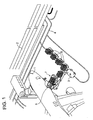
- Figure 2 shows a sketch of guide lines which drive the tow vehicle automatically according to this invention.
- Figure 3 shows a sketch of the mechanism of the tow vehicle according to this invention.
- Figure 4 shows a rough perspective drawing of the second preferred embodiment of this invention.
- Figure 5 shows an air cargo elevator according to the second preferred embodiment of this invention.
- Figure 6 shows another air cargo elevator according to the second preferred embodiment of this invention.
- Figure 7 is a sketch of the conventional cargo handling system according to a prior art.
- Figure 1 shows a rough perspective drawing of the first preferred embodiment of this invention.
- Figure 2 shows a sketch of guide lines which drive the tow vehicle automatically according to this invention.
- Figure 3 shows a sketch of the mechanism of the tow vehicle according to this invention.
- 1 is aircraft
- 2 is airport terminal
- 3 is auto-running tow vehicle
- 4 is guide line to guide to run auto-running tow vehicle
- 5 is a loading/unloading cargo door
- 6 is container/pallet dollies which are towed by auto-running tow vehicle
- 7 is container/pallet loader to load the air cargo transported, and lift up to the cargo door
- 10-15 are marks which are provided at each branch of guide line
- 16 and 17 are stop marks to stop auto-running vehicle at the aircraft parking
- 31 and 32 are sensors to detect marks 10-17
- 33 is sonic or electro-magnetic waves transmitter source
- 34 is sensor to detect the reflected sound or electro-magnetic waves emitted from transmitter source 33.
- Figure 1 shows a first embodiment of the present invention in which the air cargo is transported to or from the air cargo holding area of the airport terminal building 2 by towing container/pallet dollies 6 towed by auto-running tow vehicle 3 along guide lines 4.
- guide lines 4 that connect between the baggage holding area of airport terminal building 2 and the aircraft parking areas, marks 10, 11, 12, 13, 14, 15 at each of the branches of guide lines 4 at the aircraft parking places, and marks 16, 17 positioned where the tow vehicle should stop.
- These guide lines 4 are shown in the figure as lines, however so long as they can be detected and followed by the auto-running tow vehicle 3, they are not restricted to lines, but may be infrared rays, electro-magnetic waves or the like.
- the marks themselves may be variably comprised of, such as colored tile-like marks which appear differently from the paving or concrete inside the airport, bar code mark for indicating the location, light emitting elements for emitting infrared rays or light beams, embedded oscillators to emit electro-magnetic waves, or embedded magnets, etc.
- tow vehicle 3 is equipped with an optical reading detection device (not shown) on its bottom to follow sensors 31, 32 to detect the marks 10-17 provided along guide lines 4, a transmitter source 33 to emit sound or electro-magnetic waves to detect obstacles ahead, and a sensor 34 to detect the reflected sound or electro-magnetic waves emitted from transmitter source 33; these components are configured to enable the bottom optical reading detection device to read guide lines 4; and additionally, sensors 31, 32 to read marks 10-15 at each branch to an aircraft parking area and to detect and stop upon stop marks 16, 17.
- an optical reading detection device (not shown) on its bottom to follow sensors 31, 32 to detect the marks 10-17 provided along guide lines 4, a transmitter source 33 to emit sound or electro-magnetic waves to detect obstacles ahead, and a sensor 34 to detect the reflected sound or electro-magnetic waves emitted from transmitter source 33; these components are configured to enable the bottom optical reading detection device to read guide lines 4; and additionally, sensors 31, 32 to read marks 10-15 at each branch to an aircraft parking area and to detect and stop upon stop marks 16, 17.
- this auto-running tow vehicle 3 is configured for electro-magnetic wave type guide lines, it would include a receiver to receive those electro-magnetic signals, and if marks 10-17 established along guide lines 4 were bar codes or infrared light or light emitting element emissions, or if they were established with embedded oscillators or magnets, appropriate sensors would be included.
- the air cargo conveyance system constituted in this manner, when loading aircraft 1 with cargo from airport terminal building 2, air cargo is loaded upon container/pallet dollies 6 at the air cargo holding area of airport terminal building 2, and then the auto-running tow vehicle 3 tows container/pallet dollies 6 to the specified aircraft parking place based upon memorized route instructions.
- These instructions consist of instructions on turning right or left at the predetermined count of marks for the branches to the parking places established along the guide line 4; alternatively a specific meaning can be imparted in the case of bar codes or electro-magnetic waves and instructions on which turns to make can then be memorized.
- the auto-running tow vehicle 3 1 tows the cargo-laden container/pallet dolly 6, detecting and following guide line 4 with a line detecting device (not shown) .
- Sensors 31, 32 detect the branch positions by marks 10, 11, and based upon pre-memorized instructions, auto-running tow vehicle 3 heads toward the aircraft parking space labeled with mark 16.
- container/pallet loader 7 which is waiting in position, can then load the cargo into the aircraft 1 through the loading/unloading cargo door 5 of aircraft 1 to enable the loading of the aircraft with a minimum number of personnel.
- the operation to unload cargo from aircraft 1 is exactly the same.
- Auto-running tow vehicle 3 tows container/pallet dolly 6 to the aircraft parking place and stops, whereupon container/pallet loader 7 transfers the air cargo from aircraft 1 to container/pallet dolly 6, and then it is automatically transported to the cargo holding area inside of airport terminal building 2.
- Figure 4 shows a rough perspective drawing of the second preferred embodiment of this invention which employs an idea to connect the cargo holding area inside airport terminal building with the aircraft parking area by the foregoing guide lines which are installed underground
- Figure 5 shows an air cargo elevator according to the second preferred embodiment of this invention
- Figure 6 shows another air cargo elevator according to the second preferred embodiment of this invention.
- 1 is aircraft
- 2 is airport terminal
- 40 is an underground air cargo conveyor mechanism that connects the cargo holding area inside airport terminal building with the aircraft parking area by the guide lines and a conveyor lines
- 41 is an air cargo elevator which connects air cargo conveyor mechanism 40 and the loading/unloading door 5 of the aircraft 1 for air cargo
- 50 is ground surface
- 51 is support pillar
- 52 is elevator compartment
- 53 is support pillar
- 54 is air cargo
- 55 and 56 are conveyors
- 60 and 61 are support pillars
- 62 is actuator.
- the second embodiment comprises: an underground air cargo conveyor mechanism 40 that connects the cargo holding area inside airport terminal building 2 with the aircraft parking area by the foregoing guide lines and a conveyor belt or other type of conveyor line, and air cargo elevators 41, which are positioned at the loading/unloading doors for air cargo in the aircraft parking places to transport the cargo from the underground level to above ground, or from the above ground level to underground.
- guide lines 4 according to this invention are also present at the end of the belt conveyor as shown in the foregoing Figure 1.
- Each air cargo elevator 41 is comprised of elevator compartment 52, which can ascend or descend by means of a rack and pinion, chain or other mechanism attached to support pillars 51 which is provided beside the air cargo conveyor mechanism 40.
- Support pillars 53 installed inside elevator compartment 52 include a rack and pinion, chain or other mechanism (not shown) to move conveyor 55 up and down to transfer air cargo 54.
- the elevator compartment 52 while still below ground level, also houses forward conveyor 56 inside, as shown by the broken lines, and when elevator compartment 52 breaks the surface 50, air cargo 54 is conveyed from conveyor 55 inside air cargo elevator 41 via forward conveyor 56 into the cargo loading/unloading door 5 of aircraft 1.
- elevator compartment 52 is lowered to its lowest position, and at the same time, conveyor 55 inside elevator compartment 54 also assumes its lowest position. This causes the surface height of conveyor 55 to match that of the conveyor surface of air cargo conveyor mechanism 40, to thereby facilitate the movement of air cargo 54 between the two.
- elevator compartment 52 is raised by a rack and pinion, chain or other means (not shown) to the height shown by the solid line. At this position, a rack and pinion, chain or other means (not shown) is used to raise conveyor 55 inside of elevator compartment 52 to the position shown by the solid lines, and in addition, forward conveyor 56 deploys to the position shown by the solid lines.
- Air cargo 54 is thereby conveyed via conveyors 55, 56 into aircraft 1 via air cargo loading/unloading door 5.
- cargo 54 is conveyed from the cargo holding area inside airport terminal building 2 to air cargo loading/unloading door 5 of aircraft 1 completely without human intervention.
- the air cargo elevator 41 shown in Figure 5 was described above as having forward conveyor 56 inside elevator compartment 52, which was used to transfer air cargo 54 when elevator compartment 52 was raised, however this is not an essential means in this invention.
- a container/pallet loader 7 such as shown in Figure 1 could be used to convey the cargo from air cargo elevator 41 into air cargo loading/unloading door 5 of aircraft 1.
- air cargo elevator 41 shown in Figure 5 was described above as having support pillars 51 extended to the ground surface 50 to raise elevator compartment 52, with elevator compartment 52 being further raisable above the ground surface 50, but this arrangement could impose unreasonable forces on the rack, pinion, chain or other means (not shown) of lifting elevator compartment 52.
- support pillars 51 could be replaced by support pillars 60, as shown in Figure 6, which are raised an lowered by support pillars 61 and actuator 62.
- air cargo elevator 41 shown in Figure 5 has air cargo conveyor mechanism 40 positioned at the right hand side of the aircraft in the Figure 5, but as shown in Figure 4 in the case where the conveyance direction for air cargo 54 in air cargo conveyor mechanism 40 differs from that of the cargo loading/unloading door of aircraft 1, either a turntable or other means of changing the direction of conveyance could be located at the junction between air cargo conveyor mechanism 40 and air cargo elevator 41, or the conveyor inside of elevator compartment 52 itself could be a turntable or other apparatus that changes the direction of conveyance.
- this system instead of using ramp equipment tractors which used to be running around the tarmac parking area, this system employs a tow vehicle that can automatically follow and run upon guide lines.
- air cargo is conveyed by an underground air cargo conveyor mechanism which links the air cargo holding area in the airport terminal building and the aircraft parking area, and the air cargo is lifted up to the loading/unloading cargo door of the aircraft by an air cargo elevator.
- This system eliminates the need for human-driven equipment, such as the conventional ramp equipment tractors, to thereby eliminate the possibility of accidents such as collisions, reduce manpower costs, and shorten the time required for loading cargo, and results in other various effects.
Landscapes
- Engineering & Computer Science (AREA)
- Mechanical Engineering (AREA)
- Aviation & Aerospace Engineering (AREA)
- Architecture (AREA)
- Civil Engineering (AREA)
- Structural Engineering (AREA)
- Warehouses Or Storage Devices (AREA)
- Intermediate Stations On Conveyors (AREA)
- Control Of Position, Course, Altitude, Or Attitude Of Moving Bodies (AREA)
Applications Claiming Priority (2)
| Application Number | Priority Date | Filing Date | Title |
|---|---|---|---|
| JP2001132899 | 2001-04-27 | ||
| JP2001132899A JP2002321699A (ja) | 2001-04-27 | 2001-04-27 | 航空貨物搬送システム |
Publications (3)
| Publication Number | Publication Date |
|---|---|
| EP1253079A2 true EP1253079A2 (de) | 2002-10-30 |
| EP1253079A3 EP1253079A3 (de) | 2003-09-10 |
| EP1253079B1 EP1253079B1 (de) | 2004-12-01 |
Family
ID=18980846
Family Applications (1)
| Application Number | Title | Priority Date | Filing Date |
|---|---|---|---|
| EP02008849A Expired - Lifetime EP1253079B1 (de) | 2001-04-27 | 2002-04-19 | Luftfrachttransportsystem |
Country Status (4)
| Country | Link |
|---|---|
| US (1) | US7343995B2 (de) |
| EP (1) | EP1253079B1 (de) |
| JP (1) | JP2002321699A (de) |
| DE (1) | DE60202095T2 (de) |
Cited By (6)
| Publication number | Priority date | Publication date | Assignee | Title |
|---|---|---|---|---|
| WO2004078588A1 (de) * | 2003-03-03 | 2004-09-16 | Glenn Rolus Borgward | Fluggerät zum transport von personen und/oder gütern und system zur abfertigung solcher fluggeräte |
| WO2009098439A3 (en) * | 2008-02-05 | 2009-11-12 | Baa (Ip Holdco) Limited | Baggage system |
| FR3068268A1 (fr) * | 2017-06-29 | 2019-01-04 | Crescendi | Installation et procede de manutention et de triage automatique a haute cadence d'objets, de toutes formes, y compris instables et volumineux |
| DE102018251774A1 (de) | 2018-12-28 | 2020-07-02 | Robert Bosch Gmbh | Verfahren zum zumindest teilautomatisierten Führen eines Kraftfahrzeugs |
| EP3712093A1 (de) * | 2019-03-20 | 2020-09-23 | Siemens Aktiengesellschaft | Automatische be- und entladung von transportwagen |
| EP3898418B1 (de) * | 2018-12-21 | 2024-09-18 | Richmond Design and Marketing Limited | Transportsicherheitssystem |
Families Citing this family (26)
| Publication number | Priority date | Publication date | Assignee | Title |
|---|---|---|---|---|
| EP1634828A1 (de) * | 2002-11-08 | 2006-03-15 | Trepel Airport Equipment GmbH | Verfahren zum Beladen bzw. Entladen eines Flugzeugs sowie verfahrbare Flugzeugbeladevorrichtung |
| US20070051852A1 (en) * | 2004-09-28 | 2007-03-08 | The Boeing Company | Operational ground support system having automated primary servicing |
| JP2007041687A (ja) * | 2005-08-01 | 2007-02-15 | Murata Mach Ltd | 搬送台車システム |
| US7891609B2 (en) | 2006-08-29 | 2011-02-22 | Borealis Technical Limited | Turnaround methods |
| DE102006046691A1 (de) * | 2006-09-29 | 2008-04-10 | Siemens Ag | Cargobereich einer Flughafenanlage |
| JP5093664B2 (ja) * | 2008-02-06 | 2012-12-12 | 村田機械株式会社 | 移動体システム |
| US8589035B2 (en) * | 2008-06-17 | 2013-11-19 | Volvo Construction Equipment Ab | Method for operating a transport vehicle, a transport vehicle, a method for controllling operation of a work site and a work site system |
| RU2511734C2 (ru) * | 2012-06-06 | 2014-04-10 | Общество с ограниченной ответственностью "АэроЦентр" | Логистический терминал |
| US9126698B2 (en) * | 2012-08-31 | 2015-09-08 | Tronair, Inc. | Aircraft engine stand |
| US9771148B2 (en) * | 2013-11-29 | 2017-09-26 | Borealis Technical Limited | Airport terminal aircraft gate traffic management system and method |
| BR112017014030A2 (pt) * | 2014-12-29 | 2018-01-02 | Bbhs As | sistema para manipulação de itens de bagagem ou pacote |
| CA2917705C (en) | 2015-02-25 | 2019-06-18 | Jervis B. Webb Company | Method and system for automated luggage security inspection |
| US10133276B1 (en) * | 2015-06-19 | 2018-11-20 | Amazon Technologies, Inc. | Object avoidance with object detection and classification |
| WO2018017053A1 (en) * | 2016-07-19 | 2018-01-25 | Ford Global Technologies, Llc | Baggage transport |
| US10035598B2 (en) | 2016-10-10 | 2018-07-31 | Jervis B. Webb Company | System and method for expanding a luggage inspection area |
| US10279911B2 (en) | 2016-10-10 | 2019-05-07 | Jervis B. Webb Company | System and method for storing and sequencing luggage items |
| CN107021240B (zh) * | 2017-05-27 | 2024-03-05 | 北京京东乾石科技有限公司 | 无人机地面管理系统 |
| CN107862794B (zh) * | 2017-11-28 | 2023-10-10 | 上海量科电子科技有限公司 | 能够自动补货的自助售货机及实施方法 |
| US11667228B2 (en) | 2017-12-01 | 2023-06-06 | Fast Global Solutions, Inc. | High capacity cargo and container dolly |
| US10994865B2 (en) * | 2018-10-22 | 2021-05-04 | Goodrich Corporation | Autonomous system for air cargo end-to-end operations |
| IL264457B (en) * | 2019-01-24 | 2022-07-01 | Israel Aerospace Ind Ltd | Luggage loading system |
| US11176832B2 (en) | 2019-04-25 | 2021-11-16 | Honeywell International Inc. | Systems and methods to integrate real-time internet-connected aircraft data for cargo planning |
| US12098062B2 (en) | 2020-07-15 | 2024-09-24 | Integrated Solutions for Systems, Inc. | Autonomous robotic cargo system |
| WO2023243748A1 (ko) * | 2022-06-16 | 2023-12-21 | 엘지전자 주식회사 | 운송 로봇, 운송 수단 및 그 제어방법 |
| JP7330409B1 (ja) | 2023-04-06 | 2023-08-21 | 全日本空輸株式会社 | ドーリシステム |
| EP4663553A3 (de) * | 2025-10-27 | 2026-04-29 | Mudhar Farouq Abdulsattar Altikriti | Vollautomatisches end-to-end-gepäckhandhabungssystem mit einem authentifizierten passagiergepäckanspruch an flughäfen |
Family Cites Families (13)
| Publication number | Priority date | Publication date | Assignee | Title |
|---|---|---|---|---|
| US3935922A (en) * | 1974-07-16 | 1976-02-03 | Lear Siegler, Inc. | Vehicle guidance mechanism |
| US4307791A (en) * | 1978-12-06 | 1981-12-29 | Bell & Howell Company | Line follower vehicle with scanning head |
| CH668655A5 (de) * | 1985-03-15 | 1989-01-13 | Jd Technologie Ag | Passivspur-einrichtung zur fuehrung und steuerung von fahrerlosen transport- und montageeinheiten. |
| GB2191607B (en) * | 1986-05-09 | 1990-09-26 | Daifuku Kk | Running control system for conveyor cart |
| US4811229A (en) * | 1987-01-05 | 1989-03-07 | Hewlett-Packard Company | Control system for automatic guided vehicles |
| DE3716050A1 (de) * | 1987-05-14 | 1988-12-01 | Michael Piatscheck | Flughafenanlage |
| US5118191A (en) * | 1990-05-29 | 1992-06-02 | The United States Of America As Represented By The Secretary Of The Air Force | High contrast switchable target discriminator |
| SE501477C2 (sv) * | 1993-07-22 | 1995-02-27 | Apogeum Ab | Förfarande och anordning för styrning av AGV för val av väg vid övergång mellan skilda, icke fast relaterade arbetsområden |
| US5525884A (en) * | 1995-02-10 | 1996-06-11 | Yazaki Industrial Chemical Co., Ltd. | Automatically guided vehicle |
| WO1997002167A1 (fr) * | 1995-07-04 | 1997-01-23 | Hiroyuki Minakami | Systeme de trafic/transport |
| US6049745A (en) * | 1997-02-10 | 2000-04-11 | Fmc Corporation | Navigation system for automatic guided vehicle |
| US6129026A (en) * | 1997-05-16 | 2000-10-10 | Jervis B. Webb Company | Dual mode cargo transport apparatus and method of using same |
| US6341430B1 (en) * | 2000-03-24 | 2002-01-29 | Honda Of America Mfg., Inc. | Automated guidance vehicle guide path code templates and methods for use |
-
2001
- 2001-04-27 JP JP2001132899A patent/JP2002321699A/ja not_active Withdrawn
-
2002
- 2002-04-19 DE DE60202095T patent/DE60202095T2/de not_active Expired - Lifetime
- 2002-04-19 EP EP02008849A patent/EP1253079B1/de not_active Expired - Lifetime
- 2002-04-26 US US10/132,741 patent/US7343995B2/en not_active Expired - Fee Related
Non-Patent Citations (1)
| Title |
|---|
| None |
Cited By (6)
| Publication number | Priority date | Publication date | Assignee | Title |
|---|---|---|---|---|
| WO2004078588A1 (de) * | 2003-03-03 | 2004-09-16 | Glenn Rolus Borgward | Fluggerät zum transport von personen und/oder gütern und system zur abfertigung solcher fluggeräte |
| WO2009098439A3 (en) * | 2008-02-05 | 2009-11-12 | Baa (Ip Holdco) Limited | Baggage system |
| FR3068268A1 (fr) * | 2017-06-29 | 2019-01-04 | Crescendi | Installation et procede de manutention et de triage automatique a haute cadence d'objets, de toutes formes, y compris instables et volumineux |
| EP3898418B1 (de) * | 2018-12-21 | 2024-09-18 | Richmond Design and Marketing Limited | Transportsicherheitssystem |
| DE102018251774A1 (de) | 2018-12-28 | 2020-07-02 | Robert Bosch Gmbh | Verfahren zum zumindest teilautomatisierten Führen eines Kraftfahrzeugs |
| EP3712093A1 (de) * | 2019-03-20 | 2020-09-23 | Siemens Aktiengesellschaft | Automatische be- und entladung von transportwagen |
Also Published As
| Publication number | Publication date |
|---|---|
| US20020159869A1 (en) | 2002-10-31 |
| JP2002321699A (ja) | 2002-11-05 |
| EP1253079A3 (de) | 2003-09-10 |
| US7343995B2 (en) | 2008-03-18 |
| DE60202095T2 (de) | 2005-12-01 |
| EP1253079B1 (de) | 2004-12-01 |
| DE60202095D1 (de) | 2005-01-05 |
Similar Documents
| Publication | Publication Date | Title |
|---|---|---|
| US7343995B2 (en) | Air cargo transport system | |
| EP1253078B1 (de) | Ladebrücke zum Laden von Luftfracht | |
| KR102625918B1 (ko) | 컨테이너 자동 안내 운송 차량 및 그 작동 방법, 및 자동 운전 운송 차량을 갖는 시스템 | |
| KR101884825B1 (ko) | 무인운반차를 이용한 자동화 창고 시스템 | |
| JP5886863B2 (ja) | コンテナ積み替えシステム | |
| KR102532806B1 (ko) | 다기능 화물 운반 차량 및 방법 | |
| CN210735590U (zh) | 建筑物及其无人机的货物装卸系统 | |
| US20150191333A1 (en) | System for determination of a container's position in a vehicle and/or its trailer to be loaded with containers | |
| CN109952267B (zh) | 用于装卸集装箱的跨运车形式的门式起重装置的导航系统 | |
| JP2022546616A (ja) | 自律型荷物装置 | |
| WO2019141850A1 (en) | Autonomous self propelled ground support equipment | |
| HUT70091A (en) | Process for transferring goods load units on or from a train and device for implementing the process | |
| US9446918B2 (en) | Method for steering an airport vehicle | |
| KR20000023671A (ko) | 상품 출하 시스템 | |
| KR20050115286A (ko) | 비접촉 화물 검사 및 컨테이너 운반을 위한 다기능 이동플랫폼 | |
| KR20190044898A (ko) | 스마트 무인화물이동수단 | |
| CN212314971U (zh) | 一种转运设备以及集装箱运输系统 | |
| JP2001322720A (ja) | コンテナ荷役方法およびコンテナ荷役システム | |
| KR20170097276A (ko) | 무인 운반차 | |
| CN117470214A (zh) | 用于物料搬运车辆的导航对准系统和方法 | |
| CN214398481U (zh) | 用于安全检查的车辆输送系统 | |
| JPH08258986A (ja) | 航空貨物の自動移載装置 | |
| CN219904175U (zh) | 一种agv运输装置 | |
| JPH0659996B2 (ja) | ゴルフバツグ搬送設備 | |
| KR101472730B1 (ko) | 컨테이너 상.하역장치 및 이를 활용한 운송방법 |
Legal Events
| Date | Code | Title | Description |
|---|---|---|---|
| PUAI | Public reference made under article 153(3) epc to a published international application that has entered the european phase |
Free format text: ORIGINAL CODE: 0009012 |
|
| 17P | Request for examination filed |
Effective date: 20020419 |
|
| AK | Designated contracting states |
Kind code of ref document: A2 Designated state(s): AT BE CH CY DE DK ES FI FR GB GR IE IT LI LU MC NL PT SE TR |
|
| AX | Request for extension of the european patent |
Free format text: AL;LT;LV;MK;RO;SI |
|
| PUAL | Search report despatched |
Free format text: ORIGINAL CODE: 0009013 |
|
| AK | Designated contracting states |
Kind code of ref document: A3 Designated state(s): AT BE CH CY DE DK ES FI FR GB GR IE IT LI LU MC NL PT SE TR |
|
| AX | Request for extension of the european patent |
Extension state: AL LT LV MK RO SI |
|
| 17Q | First examination report despatched |
Effective date: 20040119 |
|
| GRAP | Despatch of communication of intention to grant a patent |
Free format text: ORIGINAL CODE: EPIDOSNIGR1 |
|
| AKX | Designation fees paid |
Designated state(s): DE FR GB |
|
| GRAS | Grant fee paid |
Free format text: ORIGINAL CODE: EPIDOSNIGR3 |
|
| GRAA | (expected) grant |
Free format text: ORIGINAL CODE: 0009210 |
|
| AK | Designated contracting states |
Kind code of ref document: B1 Designated state(s): DE FR GB |
|
| REG | Reference to a national code |
Ref country code: GB Ref legal event code: FG4D |
|
| REF | Corresponds to: |
Ref document number: 60202095 Country of ref document: DE Date of ref document: 20050105 Kind code of ref document: P |
|
| PLBE | No opposition filed within time limit |
Free format text: ORIGINAL CODE: 0009261 |
|
| STAA | Information on the status of an ep patent application or granted ep patent |
Free format text: STATUS: NO OPPOSITION FILED WITHIN TIME LIMIT |
|
| ET | Fr: translation filed | ||
| 26N | No opposition filed |
Effective date: 20050902 |
|
| PGFP | Annual fee paid to national office [announced via postgrant information from national office to epo] |
Ref country code: GB Payment date: 20140416 Year of fee payment: 13 |
|
| PGFP | Annual fee paid to national office [announced via postgrant information from national office to epo] |
Ref country code: DE Payment date: 20140430 Year of fee payment: 13 Ref country code: FR Payment date: 20140409 Year of fee payment: 13 |
|
| REG | Reference to a national code |
Ref country code: DE Ref legal event code: R119 Ref document number: 60202095 Country of ref document: DE |
|
| GBPC | Gb: european patent ceased through non-payment of renewal fee |
Effective date: 20150419 |
|
| PG25 | Lapsed in a contracting state [announced via postgrant information from national office to epo] |
Ref country code: GB Free format text: LAPSE BECAUSE OF NON-PAYMENT OF DUE FEES Effective date: 20150419 Ref country code: DE Free format text: LAPSE BECAUSE OF NON-PAYMENT OF DUE FEES Effective date: 20151103 |
|
| REG | Reference to a national code |
Ref country code: FR Ref legal event code: ST Effective date: 20151231 |
|
| PG25 | Lapsed in a contracting state [announced via postgrant information from national office to epo] |
Ref country code: FR Free format text: LAPSE BECAUSE OF NON-PAYMENT OF DUE FEES Effective date: 20150430 |