EP1255246B1 - Informationsaufzeichnungsmedium und Informationsaufzeichnungsgerät - Google Patents
Informationsaufzeichnungsmedium und Informationsaufzeichnungsgerät Download PDFInfo
- Publication number
- EP1255246B1 EP1255246B1 EP02253099A EP02253099A EP1255246B1 EP 1255246 B1 EP1255246 B1 EP 1255246B1 EP 02253099 A EP02253099 A EP 02253099A EP 02253099 A EP02253099 A EP 02253099A EP 1255246 B1 EP1255246 B1 EP 1255246B1
- Authority
- EP
- European Patent Office
- Prior art keywords
- information
- signal
- modulated
- spread spectrum
- track
- Prior art date
- Legal status (The legal status is an assumption and is not a legal conclusion. Google has not performed a legal analysis and makes no representation as to the accuracy of the status listed.)
- Expired - Lifetime
Links
- 239000003550 marker Substances 0.000 claims description 40
- 238000001228 spectrum Methods 0.000 claims description 39
- 238000000034 method Methods 0.000 claims description 14
- 230000003287 optical effect Effects 0.000 description 21
- 238000001514 detection method Methods 0.000 description 18
- 238000010586 diagram Methods 0.000 description 13
- 230000004044 response Effects 0.000 description 13
- 230000000052 comparative effect Effects 0.000 description 4
- 239000010410 layer Substances 0.000 description 4
- 238000011084 recovery Methods 0.000 description 3
- 238000004519 manufacturing process Methods 0.000 description 2
- 230000004075 alteration Effects 0.000 description 1
- 238000007796 conventional method Methods 0.000 description 1
- 230000000694 effects Effects 0.000 description 1
- 239000000284 extract Substances 0.000 description 1
- 230000006870 function Effects 0.000 description 1
- 239000002356 single layer Substances 0.000 description 1
Images



Classifications
-
- G—PHYSICS
- G11—INFORMATION STORAGE
- G11B—INFORMATION STORAGE BASED ON RELATIVE MOVEMENT BETWEEN RECORD CARRIER AND TRANSDUCER
- G11B27/00—Editing; Indexing; Addressing; Timing or synchronising; Monitoring; Measuring tape travel
- G11B27/10—Indexing; Addressing; Timing or synchronising; Measuring tape travel
- G11B27/19—Indexing; Addressing; Timing or synchronising; Measuring tape travel by using information detectable on the record carrier
- G11B27/24—Indexing; Addressing; Timing or synchronising; Measuring tape travel by using information detectable on the record carrier by sensing features on the record carrier other than the transducing track ; sensing signals or marks recorded by another method than the main recording
-
- G—PHYSICS
- G11—INFORMATION STORAGE
- G11B—INFORMATION STORAGE BASED ON RELATIVE MOVEMENT BETWEEN RECORD CARRIER AND TRANSDUCER
- G11B7/00—Recording or reproducing by optical means, e.g. recording using a thermal beam of optical radiation by modifying optical properties or the physical structure, reproducing using an optical beam at lower power by sensing optical properties; Record carriers therefor
- G11B7/004—Recording, reproducing or erasing methods; Read, write or erase circuits therefor
- G11B7/005—Reproducing
- G11B7/0053—Reproducing non-user data, e.g. wobbled address, prepits, BCA
-
- G—PHYSICS
- G11—INFORMATION STORAGE
- G11B—INFORMATION STORAGE BASED ON RELATIVE MOVEMENT BETWEEN RECORD CARRIER AND TRANSDUCER
- G11B7/00—Recording or reproducing by optical means, e.g. recording using a thermal beam of optical radiation by modifying optical properties or the physical structure, reproducing using an optical beam at lower power by sensing optical properties; Record carriers therefor
- G11B7/007—Arrangement of the information on the record carrier, e.g. form of tracks, actual track shape, e.g. wobbled, or cross-section, e.g. v-shaped; Sequential information structures, e.g. sectoring or header formats within a track
-
- G—PHYSICS
- G11—INFORMATION STORAGE
- G11B—INFORMATION STORAGE BASED ON RELATIVE MOVEMENT BETWEEN RECORD CARRIER AND TRANSDUCER
- G11B2220/00—Record carriers by type
- G11B2220/20—Disc-shaped record carriers
- G11B2220/21—Disc-shaped record carriers characterised in that the disc is of read-only, rewritable, or recordable type
- G11B2220/215—Recordable discs
- G11B2220/216—Rewritable discs
-
- G—PHYSICS
- G11—INFORMATION STORAGE
- G11B—INFORMATION STORAGE BASED ON RELATIVE MOVEMENT BETWEEN RECORD CARRIER AND TRANSDUCER
- G11B2220/00—Record carriers by type
- G11B2220/20—Disc-shaped record carriers
- G11B2220/21—Disc-shaped record carriers characterised in that the disc is of read-only, rewritable, or recordable type
- G11B2220/215—Recordable discs
- G11B2220/218—Write-once discs
-
- G—PHYSICS
- G11—INFORMATION STORAGE
- G11B—INFORMATION STORAGE BASED ON RELATIVE MOVEMENT BETWEEN RECORD CARRIER AND TRANSDUCER
- G11B2220/00—Record carriers by type
- G11B2220/20—Disc-shaped record carriers
- G11B2220/25—Disc-shaped record carriers characterised in that the disc is based on a specific recording technology
- G11B2220/2537—Optical discs
- G11B2220/2545—CDs
-
- G—PHYSICS
- G11—INFORMATION STORAGE
- G11B—INFORMATION STORAGE BASED ON RELATIVE MOVEMENT BETWEEN RECORD CARRIER AND TRANSDUCER
- G11B27/00—Editing; Indexing; Addressing; Timing or synchronising; Monitoring; Measuring tape travel
- G11B27/10—Indexing; Addressing; Timing or synchronising; Measuring tape travel
- G11B27/19—Indexing; Addressing; Timing or synchronising; Measuring tape travel by using information detectable on the record carrier
- G11B27/28—Indexing; Addressing; Timing or synchronising; Measuring tape travel by using information detectable on the record carrier by using information signals recorded by the same method as the main recording
- G11B27/30—Indexing; Addressing; Timing or synchronising; Measuring tape travel by using information detectable on the record carrier by using information signals recorded by the same method as the main recording on the same track as the main recording
- G11B27/3027—Indexing; Addressing; Timing or synchronising; Measuring tape travel by using information detectable on the record carrier by using information signals recorded by the same method as the main recording on the same track as the main recording used signal is digitally coded
-
- G—PHYSICS
- G11—INFORMATION STORAGE
- G11B—INFORMATION STORAGE BASED ON RELATIVE MOVEMENT BETWEEN RECORD CARRIER AND TRANSDUCER
- G11B7/00—Recording or reproducing by optical means, e.g. recording using a thermal beam of optical radiation by modifying optical properties or the physical structure, reproducing using an optical beam at lower power by sensing optical properties; Record carriers therefor
- G11B7/24—Record carriers characterised by shape, structure or physical properties, or by the selection of the material
- G11B7/26—Apparatus or processes specially adapted for the manufacture of record carriers
- G11B7/261—Preparing a master, e.g. exposing photoresist, electroforming
Definitions
- the present invention relates to an information recording medium having a track, which is subjected to wobbling, and an information reading apparatus for reading information of the track.
- CD-DA Compact Audio
- CD-R CD-Recordable
- CD-RW CD-ReWritable
- the optical disk In recording and reproduction of an optical disk, the optical disk needs to be rotated at a predetermined speed.
- a predetermined rotation speed can be obtained by synchronizing a rotation speed to a reproducing frequency of digital data during reproduction.
- a recordable recording medium such as CD-R and CD-RW
- digital data in an initial state, digital data is not recorded in a track, so that the same method cannot be used for controlling a rotation speed.
- a track (groove track) is subjected to wobbling according to a wobble signal obtained by performing FM modulation on a wobble reference signal, which has a predetermined fundamental frequency, based on address information, a rotation speed of the optical disk is controlled in response to the wobble reference signal extracted from a wobble signal read from the track, and the address of the track is identified by demodulating the wobble signal.
- crosstalk and so on enters a wobble signal.
- the crosstalk is caused by wobble from an adjacent track or by a recording mark formed on a track which is subjected to wobbling a wobble signal.
- the wobble signal has a degraded CN (Carrier to Noise ratio)
- CN Carrier to Noise ratio
- a problem occurs on reading of address information recorded by FM modulation and so on, and the reference signal extracted from the wobble signal becomes inaccurate.
- the same problem results from crosstalk of a wobble signal between layers. Hence, it is difficult to accurately perform writing in the multilayer disk.
- a beam when a track pitch is smaller, a beam extends substantially to an adjacent groove and is affected by a phase of wobble of the adjacent track. Besides, since a phase changes complicatedly between adjacent grooves, a value of reading signal based on reflected light of the beam is largely changed by the influence of the adjacent track.
- WO 00/45381A discloses a record carrier, playback device and method of recording information.
- US-A-5724327 discloses a record carrier having first variations of a first physical parameter corresponding to information recorded thereon and second variations of a second physical parameter relating to recovery of the information.
- an information recording medium comprising a wobbled track, characterised in that:
- a wobbling signal may be a signal in which at least a part of recording information is randomized by using a randomizing pattern.
- the influence of noise such as crosstalk can be effectively eliminated by using a plurality of randomizing patterns and frequently switching the randomizing patterns.
- the randomizing patterns on adjacent tracks are different from each other, it will be more effective.
- a wobble signal may be a signal in which at least a part of recording information is randomized by changing in a short period a fundamental frequency of a signal used for spread spectrum.
- the influence of noise such as crosstalk can be.eliminated more effectively by switching reference frequencies such that adjacent tracks are different in fundamental frequency of a signal used for spread spectrum.
- a track may have a part wobbled by recording information not being randomized.
- a track may have different wobbling amplitudes between a part corresponding to the randomized recording information and the other part corresponding to recording information not being randomized.
- the information of the part can be positively read by increasing a wobbling amplitude on a part to be suppressed in influence of crosstalk and noise from other tracks.
- a wobbling amplitude of the other part corresponding to the recording information not being randomized may be larger than that of the part corresponding to the randomized recording information.
- a randomized recording information may include a randomized specific synchronizing signal.
- a randomized specific synchronizing signal is read and compared with a specific synchronizing signal, so that it is possible to detect a method of randomizing, such as a randomizing pattern.
- a randomized recording information may further include substantial data that is randomized with the same randomizing pattern as that of the randomized specific synchronizing signal.
- the randomized recording information can be restored by using the same randomizing pattern.
- a randomized recording information includes a randomized synchronizing signal and substantial data that is randomized with a randomizing pattern indicated by the randomized synchronizing signal.
- a randomizing pattern may be different between adjacent tracks.
- a wobble signal may have different fundamental frequencies between adjacent tracks.
- the same randomizing pattern may be used in a region serving as a unit of processing the recording information.
- a fundamental frequency is randomized by the same signal in a region serving as a unit of processing the recording information.
- the unit may be an ECC block.
- the same randomizing pattern or an equal fundamental frequency is used in each ECC block.
- the unit may be equal to a data error correction unit of a recording mark.
- the same randomizing pattern or an equal fundamental frequency is used in each data error correction unit.
- Two or more kinds of randomizing patterns may be used with different occupied bands, and randomizing patterns with different occupied bands may be used between adjacent tracks.
- occupied bands of used randomizing patterns are different between adjacent tracks. Hence, the influence between adjacent tracks can be suppressed more effectively.
- the randomized recording information may include a synchronizing signal and substantial data.
- an information reading apparatus for reading an information recording medium having wobbled tracks, the information reading apparatus comprising:
- a track may be wobbled based on a wobble signal including randomized information and a track marker that is not randomized.
- the track may be wobbled based on a wobble signal including randomized information and a track marker that is not randomized, and a reading linear velocity may be measured based on a track marker signal that is included in the wobble signal and detected. Accordingly, a correct linear speed can be computed based on a waveform of a marker deformed by the influence of crosstalk and noise.
- An information reproducing device may be provided for reproducing information of the information recording medium.
- the reproducing device may be provided with a signal processing device for performing signal processing using a clock according to a linear velocity measured by the linear velocity measuring device.
- the information reproducing device can perform signal processing using an accurate clock based on a correct linear velocity.
- An information recording device may be provided for recording information in the information recording medium.
- the recording device may be provided with a signal processing device for performing signal processing using a clock based on a linear velocity measured by the linear velocity measuring device.
- the information recording device can perform signal processing using an accurate clock based on a correct linear velocity.
- Information may be randomized by using any one of a plurality of randomizing patterns
- information reading apparatus may further be provided with: a randomizing signal output device for outputting a plurality of randomizing signals by using a plurality of randomizing patterns; and a comparing device for comparing a plurality of signals outputted from the randomizing signal output device and a wobble signal read by the reading device.
- the comparing device may determine a randomizing pattern used for randomizing of the randomized information based on the compared result.
- FIGS. 1 to 5 the following will discuss an embodiment of an information recording medium according to the present invention.
- FIG. 1 is a diagram showing a signal format of recording information recorded as wobbling modulation on grooves in an optical disk, which is an information recording medium of the present embodiment.
- the recording information is referred to as groove modulation data.
- the groove modulation data of the present embodiment comprises a marker (Marker) and a synchronizing signal (Sync) that are included in a single synchronizing frame, and substantial data (Data 0 to 24) composed of 25 synchronizing frames in each ECC (error correction) block composed of 26 synchronizing frames.
- the synchronizing signal and substantial data except the marker are randomized based on a predetermined random signal, and are each recorded as a wobbling signal on a groove entirely formed in a spiral fashion.
- pit for recording predetermined RF information (e.g., video information and voice information) is formed with a light beam on the groove.
- a 70-kHz track marker is located in a marker of groove modulation data corresponding to an even-numbered track.
- a 35-kHz track marker is located in a marker of groove modulation data corresponding to an odd-number track.
- a 70-kHz synchronizing signal having a specific data pattern is located in the synchronizing signal.
- synchronizing signals (signals before randomization) are the same for all the tracks.
- the same data "10101010" is used for both of an even-numbered track and an odd-numbered track.
- address signal indicating an address of each track and error correction code in the data. It is noted that information of the data is not limited to the address signal.
- a synchronizing signal of the groove modulation data and a data signal are randomized by spread spectrum system. Namely, by multiplying (XOR) a synchronizing signal and a data signal from DC (direct current) that have 140-kHz spectrum and a random signal having a band of 280 kHz to 2.8 MHz, a synchronizing signal and a data signal are spread from 280 kHz to 2.8 MHz. During reproduction, an original signal is recovered by multiplying the same random signal, so that a synchronizing signal and a data signal of 140 kHz can be restored from DC (direct current).
- a random signal of 280 kHz to 2.8 MHz is multiplied during recovery, so that noise and crosstalk that are added to a signal before recovery is separated from a band (DC to 140 kHz) of a synchronizing signal and a data signal to the outside. Therefore, it is possible to largely reduce the influence of noise and crosstalk.
- each ECC block is randomized by using a common randomizing pattern of four randomizing patterns.
- a randomizing pattern of each ECC block is selected such that adjacent tracks have different randomizing patterns as much as possible.
- crosstalk between adjacent tracks can be reduced more effectively.
- adjacent tracks indicate tracks at a position causing crosstalk that includes adjacent tracks in the same layer or tracks formed substantially in the same area of adjacent layers, regarding a recording medium with a single layer or multiple layers.
- a groove when a groove is modulated in a radius direction, spread spectrum system is used, a data signal including an error correction signal is modulated by a specific random signal, and a groove is wobbling-modulated by the signal.
- a wobbled portion corresponding to the marker without being randomized and the other wobbled portion corresponding to the randomized synchronizing signal and data are alternately formed.
- demodulation is performed by using a specific random signal from a reproduced push-pull signal so as to remove noise entering from an adjacent track and take out a data signal.
- correction is made by an error correction signal in the ECC block so as to obtain more correct data as compared with the conventional art.
- the kind of a random signal is not limited to the above, so that any kind of signal can be selected as a random signal. However, it is desirable to frequently switch a plurality of random signals such that random signals used for data in adjacent grooves are different from each other. In this case, as described above, crosstalk between adjacent tracks can be reduced more effectively.
- a synchronizing signal and a data signal are randomized and recorded.
- a track marker is recorded without randomization.
- a circuit is not complicated in an information recorder for recording information in an optical disk or in an information reproducing device for reproducing information recorded in an optical disk.
- all data including a track marker may be randomized and recorded.
- a track marker when a track marker is not randomized, in order to increase accuracy of reading on a marker not being randomized, it is more effective to raise a modulation factor (amplitude factor) of a groove on the part.
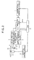
- FIG. 2 the following will discuss the configuration of a disk cutting machine for manufacturing a master disk.
- the cutting machine is provided with: a random signal generating circuit 1 for generating a random signal; a modulator 2 for multiplying a synchronizing signal and a data signal in the groove modulation data having the above-mentioned signal format by a random signal; a recording head 3 for forming grooves on a master optical disk 20; a slider 4 for driving the recording head 3 in a radius direction of the disk; a slider position detection circuit 5 for detecting a position of the recording head 3 in a radius direction of the disk; a slider control circuit 6 for controlling a sliding position of the slider 4; an optical recording driver 8 for controlling laser light emitted from the recording head 3; a drive 9 for rotatably driving the master disk; a rotation control circuit 10 for controlling the drive 9; and a CPU 11 for controlling the random signal generating circuit 1; the modulator 2; the slider position detection circuit 5; the slider control circuit 6; the optical recording driver 8; and the rotation control circuit 10.
- the groove modulation data having the above-mentioned signal format are outputted to the modulator 2 via the CPU 11. It is noted that an address and so on are recorded in a memory and so on in the CPU 11 in advance as necessary. Meanwhile, the random signal generating circuit 1 generates a random signal having a band of 280 kHz to 2.8 MHz and outputs the signal to the modulator 2.
- the groove modulation data outputted from the CPU 11 is multiplied by a random signal as necessary, which is outputted from the random signal generating circuit 1.
- a synchronizing signal and a data signal are multiplied by a random signal before randomization.
- An output signal of the modulator 2 is inputted to the slider control circuit 6, and the recording head 3 is driven by the slider 4.
- a track marker, a synchronizing signal modulated by a random signal, and a data signal modulated by a random signal are recorded in a master optical disk in the wobbling form of grooves.
- a recordable optical disk is manufactured in large quantities by using such a master optical disk 20 according to FIG. 1 .
- FIG. 3 is a block diagram showing the reading apparatus.
- Such a reading apparatus is provided in a recorder or a reproducing device of an optical disk.
- FIG. 3 shows an example of the reading apparatus of the present invention that is applied to a reproducing device of an optical disk, on which a synchronizing signal and a data signal are modulated by using four kinds of random signal patterns as described above.
- a reading apparatus 100 is provided with: a push-pull signal generating circuit 21 for generating a push-pull signal from an output signal of a pair of detectors; a filter 22 for passing a 70 kHz-signal; a detection circuit 23 for detecting a 70 kHz-track marker; a filter 24 for passing a 35 kHz-signal; a detection circuit 25 for detecting a 35 kHz marker; a linear velocity detection circuit 26 for detecting a linear velocity of an optical disk in response to signals from the detection circuit 23 and the detection circuit 25; a clock generating circuit 27 for generating a clock depending upon a linear speed detected by the linear speed detection circuit 26; a multitap delay circuit 29 for receiving a signal from the push-pull signal generating circuit 21 and the clock generating circuit 27; a memory 30 for storing output signal from the multitap delay circuit 29; a first sink pattern generator 31 for generating a synchronizing signal modulated by a first random modulation pattern; a second
- a 70-kHz track marker indicating an even-numbered track is extracted from a push-pull signal outputted from the push-pull signal generating circuit 21, and the track marker is detected in the marker detection circuit 23.
- a 35-kHz track marker indicating an odd-numbered track is extracted from a push-pull signal outputted from the push-pull signal generating circuit 21, and the track marker is detected in the marker detection circuit 25.
- a linear velocity of track reading is computed based on track markers detected in the marker detection circuit 23 and the marker detection circuit 25.
- FIG. 4 is a diagram showing a method for computing a linear velocity.
- a linear velocity is computed by measuring a distance (time) between the centers of crests of track markers.
- a track marker is detected with a waveform which is different from an actual waveform due to the influence of crosstalk and noise.
- the center of the crest of a track marker is used as a reference in the present embodiment, it is possible to eliminate the influence of a detected error of a track marker when a linear velocity is computed.
- a clock is generated according to a linear velocity computed in the linear velocity detection circuit 26.
- a clock outputted from the clock generating circuit 27 is outputted to a servo system for controlling the number of revolution of a disk. Further, the clock is inputted to the multitap delay circuit 29.
- output signals of the push-pull signal generating circuit 21 are sequentially sampled in response to clocks outputted from the clock generating circuit 27, and the signal is stored in the memory 30. Moreover, the signal is outputted to the switch 37 from the push-pull signal generating circuit 21. Signals obtained by sequentially shifting phases of push-pull signals are outputted from the multitap delay circuit 29 in response to clocks outputted from the clock generating circuit 27. In this manner, since push-pull signals are stored with shifted phases, signals can be prepared without phase differences from output signals of the first to fourth random modulation pattern generators 31 to 34, and signals can be compared in the comparator 36.
- signals stored in the memory 30 and signals generated in the first to fourth random modulation pattern generators 31 to 34 are compared with each other.
- signals outputted from the first to fourth random modulation pattern generators 31 to 34 when some signals match signals of the memory 30, it is determined that a push-pull signal is modulated by the corresponding randomizing pattern.
- comparison is made between a waveform of a signal sampled according to a clock locked to a linear velocity and four kinds of signals outputted from the random modulation pattern generators 31 to 34 to find a matching signals.
- signals conform to each other it is determined that the waveform is a synchronizing signal after modulation and is a point having conforming phases.
- the ECC blocks have the same synchronizing signals. Further, synchronizing signals of the ECC blocks are modulated by any of the first to fourth random signals. Therefore, one of synchronizing signals, which are outputted from the multitap delay circuit 29 and are stored in the memory 30 after modulation, always match a signal outputted from one of the first to fourth random modulation pattern generators 31 to 34.
- Whether a signal matches or not is determined by a shift from a signal to be matched. A shift if detected, and when a shift is at a predetermined value or less, the signal is considered to be a matching signal.
- modulation is performed by using the same random series in the same ECC block.
- demodulation is performed by using the same random series until the first synchronizing signal of the subsequent ECC block.
- a randomized pattern used for the subsequent ECC block is found in advance.
- a randomizing pattern thereof is prepared, and a phase of a synchronizing signal in each ECC and a phase of a randomizing pattern can be matched with each other relative to a front position of the ECC block where detection is made.
- the comparator 36 switches a switch 37 so as to select a signal to be matched in the comparator 36 from push-pull signals outputted from the multitap delay circuit 29.
- a synchronizing signal and a data signal are outputted with suitable phases from the multitap delay circuit 29 via the switch 37.
- the comparator 36 switches the switch 45 so as to select a random signal corresponding to a signal, which is a target of matching determination, among the first to fourth random modulation pattern generators 31 to 34. For example, when an output signal of the first random modulation pattern generator 31 matches a predetermined signal stored in the memory 30, a first random signal, which is an output signal of the first random signal generator 41, is selected.
- a push-pull signal selected from output signals of the multitap delay circuit 29 is multiplied by a random signal selected from the first to fourth random signals.
- a synchronizing signal and a data signal are demodulated by a predetermined random signal and are outputted from the demodulator 46 as demodulating signals.
- an error is corrected in response to a demodulating signal outputted from the demodulator 46, and a signal after error correction is transmitted to a CPU (not shown).
- a recording clock generator 48 a recording clock is generated in response to a demodulating signal outputted from the demodulator 46.
- the synchronizing signal extracting section 49 extracts a synchronizing signal outputted from the comparator 36.
- a synchronizing signal extracted in the synchronizing signal extracting section 49 is outputted to a servo system for controlling the number of revolution of a disk, and the synchronizing signal is used for controlling a spindle servo and so on.
- an information recording and reproducing apparatus 200 is provided with: a recording and reproducing head 51; a head amplifier 52 for receiving a reproduced signal from the recording and reproducing head; a physical format decoder 53 for receiving an output signal of the head amplifier 52; a video decoder 55 for receiving an output signal of the physical format decoder 53; a graphic user interface picture multiplexing section 56 for multiplexing a graphic user interface image in response to an output signal of the video decoder 55; and an NTSC encoder 57 for performing NTSC encoding in response to an output signal of the graphic user interface picture multiplexing section 56.
- the information recording and reproducing apparatus 200 is provided with: a time base corrector 58 for correcting synchronization of a video signal; an analog tuner 59; a separator 60 for separating a luminance signal and a color signal in response to an output signal of the time base corrector 58 and an output signal of the analog tuner 59; an MPEG encoder 61 for performing MPEG encoding in response to an output signal of the separator 60; a physical format encoder 62 for receiving an output signal of the MPEG encoder 61; a pulse generating circuit 63 for receiving an output signal of the physical format encoder 62; and a recording driver 64 for controlling laser light emitted from the recording and reproducing head 51 in response to an output signal of the pulse generating circuit 63.
- the information recording and reproducing apparatus 200 is provided with: a tracking control circuit 67 for controlling tracking of the recording and reproducing head 51 based on an output signal of the head amplifier 52; and a focus control circuit 68 for controlling focus of the recording and reproducing head 51 based on an output signal of the recording and reproducing head 51.
- the information recording and reproducing apparatus 200 is provided with the reading apparatus 100 of FIG. 3 .
- a signal obtained from the recording and reproducing head 51 via the head amplifier 52 is inputted to the push-pull signal generating circuit of the reader 100.
- An output signal of the ECC block generator 47 is supplied to the CPU 71 for controlling the parts of the information recording and reproducing device 200.
- a data signal such as address information is used for controlling the information recording and reproducing apparatus 200.
- the data signal is included in an output signal of the ECC block generator 47.
- output signals of the clock generating circuit 27 and the synchronizing signal extracting section 49 are transmitted to the spindle control circuit 73.
- the spindle control circuit 73 controls the spindle motor 72 for rotatably driving a disk.
- FIG. 6 is a block diagram showing a disk cutting machine for recording a wobble signal which is subjected to FM modulation.
- the disk cutting machine is provided with: a wobble generating circuit 101 for generating a wobble reference signal having a predetermined fundamental frequency; an FM modulating circuit 102 for performing FM modulation on the wobble reference signal; a recording head 103 for forming a groove on a master optical disk; a slider 104 for driving the recording head 103 in a radius direction of a disk; a slider position detection circuit 105 for detecting a position of the recording head 103 driven by the slider 104; a slider control circuit 106 for controlling the slider 104; an optical recording driver 108 for controlling laser light emitted from the recording head 103; a spindle motor 109 for rotatably driving a master disk; a rotation control circuit 110 for controlling the spindle motor 109; and a CPU 111 for controlling the FM modulating circuit 102, the slider position detection circuit 105, the slider control
- a data signal such as address information is supplied to the FM modulating circuit 102 via the CPU 111.
- An unmodulated wobble reference signal outputted from the wobble generating circuit 101 is subjected to FM modulation in the FM modulating circuit 102 based on a data signal outputted from the CPU 111.
- a modulated signal outputted from the FM modulating circuit 102 is inputted to the slider control circuit 106.
- the slender 104 is driven according to a modulated signal so as to form a wobbled groove on a master disk.
- FIG. 7A and 7B show the shapes of grooves on a plurality of adjacent tracks.
- FIG. 8 shows the positional relationship of a beam and a groove when a wobble is read. When a wobble signal is read, a difference between a signal corresponding to a region of A+D and a signal corresponding to a region of B+C in the beam shown in FIG. 8 is used.
- beam when a track pitch is smaller, beam extends substantially to an adjacent groove and is affected by a phase of a wobble of an adjacent track.
- FIG. 7A the phase relationship between adjacent grooves is changed in a complicated manner.
- FIG. 7B when adjacent grooves are in phase, crosstalk, which enters a signal corresponding to the A+D region and a signal corresponding to the B+C region, is in opposite phase.
- a difference between a signal corresponding to the A+D region and a signal corresponding to the B+C region reaches a maximum value.
- FIG. 8 also shows marked pits. Because of a shape of beam, a shape of a pit, aberration of a lens, crosstalk of a pit on an adjacent groove, values corresponding to mark pits of the A+D region and the B+C region do not always conform to each other. The difference is expressed in output of wobble detection.
- randomizing patters used between adjacent tracks are made different by using four kinds of randomizing patterns.
- the number of randomizing patterns can be suitably determined depending upon the configuration of the recording medium such that the same randomizing pattern is not used on adjacent tracks.
- all the ECC blocks have the same synchronizing signals, and modulation is performed on a synchronizing signal and a data signal in each ECC block by using the same randomizing pattern.
- the ECC blocks use different synchronizing signals, and a synchronizing signal and a data signal in the same ECC block use different randomizing patterns. Arrangement is made such that the same randomizing patterns are not arranged between adjacent tracks. In this case, a random signal can be demodulated by allowing a synchronizing signal to correspond to a randomizing pattern used for a data signal.
- a circuit used for reading a synchronizing signal and a data signal is complicated. Since a synchronizing signal and a data signal have different occupied bands, it is possible to reduce the influence of crosstalk on a synchronizing signal from a data signal. Hence, it is possible to improve accuracy of reading a synchronizing signal.
- occupied bands of randomizing patterns between adjacent tracks are not limited.
- the influence of crosstalk between adjacent tracks can be further reduced by separating occupied bands of randomizing patterns between adjacent tracks.
- random data is produced for a synchronizing signal and a data signal, and a track marker is recorded without randomization.
- all data may be randomized.
- a data extracting clock is generated by using a clock control circuit, which uses a PLL, and a revolution detector, and data can be obtained by the same method.
Landscapes
- Optical Recording Or Reproduction (AREA)
- Indexing, Searching, Synchronizing, And The Amount Of Synchronization Travel Of Record Carriers (AREA)
Claims (20)
- Informationsaufzeichnungsmedium, das eine gewobbelte Spur umfasst, dadurch gekennzeichnet, dass:die Spur einen Teil, der eingerichtet ist, um Wobbeln auf Basis eines Wobbelsignals unterzogen zu werden,in dem wenigstens ein Teil von Aufzeichnungsinformationen durch Spread-Spectrum moduliert ist, und einen Teil umfasst, der eingerichtet ist, um mittels Aufzeichnungsinformationen gewobbelt zu werden, die nicht durch Spread-Spectrum moduliert sind, unddie Spur unterschiedliche Wobbelamplituden zwischen einem Teil, der den Aufzeichnungsinformationen entspricht, die durch Spread-Spectrum moduliert sind, und dem anderen Teil, der Aufzeichnungsinformationen entspricht, die nicht durch Spread-Spectrum moduliert sind, aufweist.
- Informationsaufzeichnungsmedium nach Anspruch 1, wobei das Wobbelsignal ein Signal ist, bei dem wenigstens ein Teil von Aufzeichnungsinformationen durch Spread-Spectrum unter Verwendung eines Modulationsmusters moduliert ist.
- Informationsaufzeichnungsmedium nach Anspruch 1, wobei das Wobbelsignal ein Signal ist, bei dem wenigstens ein Teil von Aufzeichnungsinformationen durch Spread-Spectrum moduliert ist, von dem eine fundamentale Frequenz in einem kurzen Zeitraum geändert wird.
- lnformationsaufzeichnungsmedium nach einem der vorhergehenden Ansprüche, wobei eine Wobbelamplitude des anderen Teils, der den Aufzeichnungsinformationen entspricht, die nicht durch Spread-Spectrum moduliert sind, größer ist als die des Teils, der den Aufzeichnungsinformationen entspricht, die durch Spread-Spectrum moduliert sind.
- Informationsaufzeichnungsmedium nach einem der vorhergehenden Ansprüche, wobei die Aufzeichnungsinformationen, die durch Spread-Spectrum moduliert sind, ein spezifisches Synchronisierungssignal enthalten, das durch Spread-Spectrum moduliert ist.
- Informationsaufzeichnungsmedium nach Anspruch 5, wobei die Aufzeichnungsinformationen, die durch Spread-Spectrum moduliert sind, des Weiteren wesentliche Daten enthalten, die mit dem gleichen Modulationsmuster wie das des spezifischen Synchronisierungssignals, das durch Spread-Spectrum moduliert ist, moduliert sind.
- Informationsaufzeichnungsmedium nach einem der Ansprüche 1 bis 4, wobei die Aufzeichnungsinformationen, die durch Spread-Spectrum moduliert sind, ein Synchronisierungssignal, das durch Spread-Spectrum moduliert ist, und wesentliche Daten enthalten, die mit einem Modulationsmuster moduliert sind, das durch das Synchronisierungssignal angezeigt wird, das durch Spread-Spectrum moduliert ist.
- Informationsaufzeichnungsmedium nach Anspruch 2, wobei das Modulationsmuster zwischen benachbarten Spuren unterschiedlich ist.
- Informationsaufzeichnungsmedium nach Anspruch 3, wobei das Wobbelsignal zwischen benachbarten Spuren unterschiedliche fundamentale Frequenzen aufweist.
- Informationsaufzeichnungsmedium nach Anspruch 2, wobei ein einzelnes Modulationsmuster in einer Verarbeitungseinheit zum Verarbeiten der Aufzeichnungsinformationen verwendet wird.
- Informationsaufzeichnungsmedium nach Anspruch 3, wobei das Wobbelsignal eine einzelne fundamentale Frequenz in einer Verarbeitungseinheit zum Verarbeiten der Aufzeichnungsinformationen hat.
- Informationsaufzeichnungsmedium nach Anspruch 10 oder 11, wobei die Verarbeitungseinheit ein Fehlerkorrektur-Block (ECC-Block) ist.
- Informationsaufzeichnungsmedium nach Anspruch 10 oder 11, wobei die Verarbeitungseinheit eine Datenfehlerkorrektureinheit einer Aufzeichnungsmarkierung ist.
- Informationsaufzeichnungsmedium nach Anspruch 2, wobei zwei oder mehr Arten von Modulationsmustern mit unterschiedlichen besetzten Bändern verwendet werden und Modulationsmuster mit unterschiedlichen besetzten Bändern zwischen benachbarten Spuren verwendet werden.
- Informationsaufzeichnungsmedium nach Anspruch 1, wobei die Aufzeichnungsinformationen, die durch Spread-Spectrum moduliert sind, ein Synchronisierungssignal und wesentliche Daten enthalten.
- Informationslesevorrichtung (100) zum Lesen eines Informationsaufzeichnungsmediums mit gewobbelten Spuren, wobei die Informationslesevorrichtung umfasst:eine Leseeinrichtung (23, 25), die eingerichtet ist, um ein Wobbelsignal auf Basis von Wobbeln der Spur zu lesen;eine Erfassungseinrichtung (23, 25), die eingerichtet ist, um ein Spurmarkierungssignal zu erfassen, das in dem Wobbelsignal enthalten ist; undeine Lineargeschwindigkeitsmesseinrichtung (26), die eingerichtet ist, um eine Lineargeschwindigkeit des Informationsaufzeichnungsmediums auf Basis des erfassten Spurmarkierungssignals zu messen;dadurch gekennzeichnet, dass die Vorrichtung Einrichtungen umfasst, die eingerichtet sind, um Folgendes zu lesen:die Spur, die eingerichtet ist, um auf Basis eines Wobbelsignals gewobbelt zu werden, das Aufzeichnungsinformationen enthält, die durch Spread-Spectrum moduliert sind, und eine Spurmarkierung enthält, die nicht durch Spread-Spectrum moduliert ist;wobei die Spur einen Teil aufweist, der eingerichtet ist, um durch Aufzeichnungsinformationen gewobbelt zu werden, die nicht durch Spread-Spectrum moduliert sind; undwobei die Spur unterschiedliche Wobbelamplituden zwischen einem Teil, der den Aufzeichnungsinformationen entspricht, die durch Spread-Spectrum moduliert sind, und dem anderen Teil, der Aufzeichnungsinformationen entspricht, die nicht durch Spread-Spectrum moduliert sind, aufweist.
- Informationslesevorrichtung nach Anspruch 16, wobei, wenn benachbarte Kämme von Spurmarkierungssignalen, die in dem Wobbelsignal enthalten sind, Breiten N1 und N2 aufweisen und ein Tal zwischen den Kämmen der Spurmarkierungssignale eine Breite M aufweist, die Lineargeschwindigkeitsmesseinrichtung die Distanz L zwischen den Mitten der Kämme der benachbarten Spurmarkierungssignale anhand der folgenden Gleichung berechnet:

- Informationslesevorrichtung (100, 200) nach Anspruch 16, des Weiteren eine Informationswiedergabevorrichtung (51, 52, 55, 56, 57, 71) umfassend, die eingerichtet ist, um Informationen wiederzugeben, die in der Spur aufgezeichnet sind, wobei die Informationswiedergabevorrichtung eine Signalverarbeitungseinrichtung (71) aufweist, die eingerichtet ist, um ein Signal unter Verwendung eines Taktes gemäß einer von der Lineargeschwindigkeitsmesseinrichtung gemessenen Lineargeschwindigkeit zu verarbeiten.
- Informationslesevorrichtung (100, 200) nach Anspruch 16, des Weiteren eine Informationsaufzeichnungsvorrichtung (51, 58, 59, 60, 61, 62, 63, 64, 71) umfassend, die eingerichtet ist, um Informationen in der Spur aufzuzeichnen, wobei die Informationsaufzeichnungsvorrichtung eine Signalverarbeitungseinrichtung (71) aufweist, die eingerichtet ist, um ein Signal unter Verwendung eines Taktes gemäß einer von der Lineargeschwindigkeitsmesseinrichtung gemessenen Lineargeschwindigkeit zu verarbeiten.
- Informationslesevorrichtung (100) nach einem der Ansprüche 16 bis 19, wobei die Informationen, die durch Spread-Spectrum moduliert sind, unter Verwendung eines einer Vielzahl von Modulationsmustern moduliert werden, wobei die Informationslesevorrichtung des Weiteren umfasst:eine Modulationssignalausgabeeinrichtung (31, 32, 34), die eingerichtet ist, um eine Vielzahl von Modulationssignalen unter Verwendung einer Vielzahl von Modulationsmustern im Spread-Spectrum auszugeben; undeine Vergleichseinrichtung (36), die eingerichtet ist, um eine Vielzahl von Signalen, die von der Modulationssignalausgabeeinrichtung ausgegeben werden, und ein Wobbelsignal, das von der Leseeinrichtung gelesen wird, zu vergleichen, wobei die Vergleichseinrichtung des Weiteren eingerichtet ist, um ein Modulationsmuster, das zum Modulieren der Informationen verwendet wird, die durch Spread-Spectrum moduliert sind, auf Basis des Vergleichsergebnisses zu bestimmen.
Applications Claiming Priority (2)
| Application Number | Priority Date | Filing Date | Title |
|---|---|---|---|
| JP2001134948 | 2001-05-02 | ||
| JP2001134948 | 2001-05-02 |
Publications (3)
| Publication Number | Publication Date |
|---|---|
| EP1255246A2 EP1255246A2 (de) | 2002-11-06 |
| EP1255246A3 EP1255246A3 (de) | 2005-02-09 |
| EP1255246B1 true EP1255246B1 (de) | 2008-07-16 |
Family
ID=18982516
Family Applications (1)
| Application Number | Title | Priority Date | Filing Date |
|---|---|---|---|
| EP02253099A Expired - Lifetime EP1255246B1 (de) | 2001-05-02 | 2002-05-01 | Informationsaufzeichnungsmedium und Informationsaufzeichnungsgerät |
Country Status (4)
| Country | Link |
|---|---|
| US (2) | US7020062B2 (de) |
| EP (1) | EP1255246B1 (de) |
| AT (1) | ATE401647T1 (de) |
| DE (1) | DE60227596D1 (de) |
Families Citing this family (12)
| Publication number | Priority date | Publication date | Assignee | Title |
|---|---|---|---|---|
| US6711225B1 (en) * | 2000-05-26 | 2004-03-23 | Marvell International, Ltd. | Method and apparatus for synchronization of a bit stream for long latency data detection |
| EP1293971B1 (de) * | 2001-09-14 | 2008-07-16 | Pioneer Corporation | Informationsaufzeichnungsmedium, Informationswiedergabegerät und Informationsaufzeichnungsgerät |
| JP3715273B2 (ja) * | 2002-11-26 | 2005-11-09 | パイオニア株式会社 | 画像データの平滑化処理装置、平滑化処理方法及び平滑化処理プログラム |
| JP4063713B2 (ja) | 2003-05-26 | 2008-03-19 | パイオニア株式会社 | 情報再生装置及び情報再生方法 |
| JP2005004825A (ja) * | 2003-06-10 | 2005-01-06 | Pioneer Electronic Corp | 情報記録媒体、情報再生装置及び情報再生方法 |
| JP2005071495A (ja) * | 2003-08-26 | 2005-03-17 | Pioneer Electronic Corp | 情報記録媒体、情報再生装置及び情報再生方法 |
| KR100545379B1 (ko) * | 2004-03-09 | 2006-01-24 | 삼성전자주식회사 | 휘도/색차 성분 분리 기능이 내장된 광기록재생 장치 |
| US7281116B2 (en) * | 2004-07-30 | 2007-10-09 | Hewlett-Packard Development Company, L.P. | Multiprocessor system having plural memory locations for respectively storing TLB-shootdown data for plural processor nodes |
| JP4370519B2 (ja) * | 2004-10-25 | 2009-11-25 | ソニー株式会社 | 光情報再生装置及び光情報再生方法 |
| WO2009013743A2 (en) * | 2007-07-23 | 2009-01-29 | Nir Ben Zeev | Prevention of software and movie piracy |
| US8405925B2 (en) | 2011-06-01 | 2013-03-26 | International Business Machines Corporation | Track-dependent data randomization mitigating false VFO detection |
| DE102013112548B4 (de) * | 2013-11-14 | 2022-04-21 | Fujitsu Technology Solutions Intellectual Property Gmbh | Sendevorrichtung, Verwendung einer Sendevorrichtung und Verfahren |
Family Cites Families (13)
| Publication number | Priority date | Publication date | Assignee | Title |
|---|---|---|---|---|
| DE69230168T2 (de) * | 1991-12-02 | 2000-04-20 | Koninklijke Philips Electronics N.V. | Geschlossenes Informationssystem mit Kopierschutz |
| WO1996027191A1 (en) * | 1995-02-28 | 1996-09-06 | Isis Innovation Limited | Covert identification |
| US5917910A (en) * | 1995-10-16 | 1999-06-29 | Sony Corporation | Encrypting method and apparatus, recording method, decrypting method and apparatus, and recording medium |
| JP3103505B2 (ja) * | 1996-06-26 | 2000-10-30 | 三菱電機株式会社 | 光ディスク及び光ディスク駆動装置 |
| JP3300628B2 (ja) * | 1997-03-04 | 2002-07-08 | 富士通株式会社 | 情報記憶装置及び情報記憶媒体 |
| KR100403270B1 (ko) * | 1997-12-29 | 2004-03-20 | 삼성전자주식회사 | 디지털기록매체의저작권을보호하는방법및장치,그리고,그디지털기록매체 |
| AU4407199A (en) * | 1998-05-20 | 1999-12-06 | Recording Industry Association Of America | Copy protection method using broken modulation rules |
| EP1055237B1 (de) * | 1998-12-09 | 2008-03-26 | Koninklijke Philips Electronics N.V. | Verfahren und vorrichtung zur informationsaufzeichnung in einheiten |
| IL138671A (en) * | 1999-01-27 | 2005-12-18 | Koninkl Philips Electronics Nv | Record carrier, playback device and method of recording information |
| JP4026989B2 (ja) * | 1999-07-08 | 2007-12-26 | 富士通株式会社 | 磁気ディスク装置および最適オフセット測定方法 |
| EP1098301A2 (de) * | 1999-11-03 | 2001-05-09 | Samsung Electronics Co., Ltd. | Adressierungsverfahren für physikalische Identifikationsdaten das gewobbelte Signale nutzt, Schaltung zur Kodierung von Wobbeladressen, Verfahren und Schaltung zur Detektion von Wobbeladressen, und Aufzeichnungsmedium |
| JP2001216650A (ja) | 2000-01-28 | 2001-08-10 | Sony Corp | 記録方法、ディスク製造装置及び記録媒体 |
| KR100416542B1 (ko) * | 2000-12-04 | 2004-02-05 | 삼성전자주식회사 | 워블변조 트랙이 형성된 기록매체, 그 헤더 영역 검출방법및 검출장치 |
-
2002
- 2002-05-01 AT AT02253099T patent/ATE401647T1/de not_active IP Right Cessation
- 2002-05-01 EP EP02253099A patent/EP1255246B1/de not_active Expired - Lifetime
- 2002-05-01 DE DE60227596T patent/DE60227596D1/de not_active Expired - Lifetime
- 2002-05-02 US US10/136,445 patent/US7020062B2/en not_active Expired - Fee Related
-
2006
- 2006-01-18 US US11/333,259 patent/US20060114767A1/en not_active Abandoned
Also Published As
| Publication number | Publication date |
|---|---|
| US20020172119A1 (en) | 2002-11-21 |
| US20060114767A1 (en) | 2006-06-01 |
| EP1255246A2 (de) | 2002-11-06 |
| EP1255246A3 (de) | 2005-02-09 |
| ATE401647T1 (de) | 2008-08-15 |
| DE60227596D1 (de) | 2008-08-28 |
| US7020062B2 (en) | 2006-03-28 |
Similar Documents
| Publication | Publication Date | Title |
|---|---|---|
| JP3090662B1 (ja) | 光ディスクおよび光ディスク記録再生装置 | |
| KR100279789B1 (ko) | 워블신호 검출회로, 워블이상 검출회로, 이들을 사용한 정보처리장치 및 정보처리방법과 이들에 사용하는 기록매체 | |
| EP0801382B1 (de) | Vorrichtung und Verfahren zur optischen Aufzeichnung und Wiedergabe von Information | |
| US7706224B2 (en) | Information recording medium, information reading apparatus and information recording apparatus | |
| EP1255246B1 (de) | Informationsaufzeichnungsmedium und Informationsaufzeichnungsgerät | |
| EP1519379B1 (de) | Optisches aufzeichnungsmedium, informationsverarbeitungseinrichtung mit dem aufzeichnungsmedium und datenaufzeichnungsverfahren | |
| US6687206B1 (en) | Information recording method and apparatus | |
| JP3881835B2 (ja) | 記録再生装置 | |
| JP4467849B2 (ja) | 情報記録媒体、情報読取装置および情報記録装置 | |
| EP0880132A2 (de) | Gerät und Verfahren zur Detektion von Vorsatzlöchern | |
| JP4220722B2 (ja) | 情報記録媒体および情報読取装置 | |
| EP1225571B1 (de) | Gerät zur Detektion von Vorsatzlöchern | |
| KR100253805B1 (ko) | 정보 기록 방법 및 장치 | |
| JP3426303B2 (ja) | 光ディスク及びその記録情報再生装置 | |
| US20060120263A1 (en) | Optical recording medium and its information recording method, and recorder | |
| KR100682365B1 (ko) | 동기 신호 검출 장치 및 동기 신호 검출 방법 | |
| EP1494223B1 (de) | Informationsaufzeichnungsmedium und Vorrichtung und Verfahren zur Wiedergabe von Informationen | |
| JP2721464B2 (ja) | 光ディスク記録装置及び光ディスク再生装置 | |
| JP4132525B2 (ja) | 情報記録装置 | |
| JP3073205B2 (ja) | 光ディスクおよび光ディスク記録再生装置 | |
| KR100392960B1 (ko) | 산/골 기록방식 광디스크 및 그 기록/재생 장치 | |
| JP3073204B2 (ja) | 光ディスクおよび光ディスク記録再生装置 | |
| JP2003178465A (ja) | 情報記録媒体、情報読取装置および情報記録装置 | |
| JPH05225585A (ja) | 光ディスク装置およびその制御方法 | |
| JP2004319089A (ja) | プリピット検出装置、プリピット検出方法 |
Legal Events
| Date | Code | Title | Description |
|---|---|---|---|
| PUAI | Public reference made under article 153(3) epc to a published international application that has entered the european phase |
Free format text: ORIGINAL CODE: 0009012 |
|
| AK | Designated contracting states |
Kind code of ref document: A2 Designated state(s): AT BE CH CY DE DK ES FI FR GB GR IE IT LI LU MC NL PT SE TR |
|
| AX | Request for extension of the european patent |
Free format text: AL;LT;LV;MK;RO;SI |
|
| PUAL | Search report despatched |
Free format text: ORIGINAL CODE: 0009013 |
|
| AK | Designated contracting states |
Kind code of ref document: A3 Designated state(s): AT BE CH CY DE DK ES FI FR GB GR IE IT LI LU MC NL PT SE TR |
|
| AX | Request for extension of the european patent |
Extension state: AL LT LV MK RO SI |
|
| RIC1 | Information provided on ipc code assigned before grant |
Ipc: 7G 11B 20/14 B Ipc: 7G 11B 7/007 A |
|
| 17P | Request for examination filed |
Effective date: 20050728 |
|
| AKX | Designation fees paid |
Designated state(s): AT BE CH CY DE DK ES FI FR GB GR IE IT LI LU MC NL PT SE TR |
|
| GRAP | Despatch of communication of intention to grant a patent |
Free format text: ORIGINAL CODE: EPIDOSNIGR1 |
|
| GRAS | Grant fee paid |
Free format text: ORIGINAL CODE: EPIDOSNIGR3 |
|
| GRAA | (expected) grant |
Free format text: ORIGINAL CODE: 0009210 |
|
| AK | Designated contracting states |
Kind code of ref document: B1 Designated state(s): AT BE CH CY DE DK ES FI FR GB GR IE IT LI LU MC NL PT SE TR |
|
| REG | Reference to a national code |
Ref country code: GB Ref legal event code: FG4D |
|
| REG | Reference to a national code |
Ref country code: CH Ref legal event code: EP |
|
| REF | Corresponds to: |
Ref document number: 60227596 Country of ref document: DE Date of ref document: 20080828 Kind code of ref document: P |
|
| REG | Reference to a national code |
Ref country code: IE Ref legal event code: FG4D |
|
| NLV1 | Nl: lapsed or annulled due to failure to fulfill the requirements of art. 29p and 29m of the patents act | ||
| PG25 | Lapsed in a contracting state [announced via postgrant information from national office to epo] |
Ref country code: NL Free format text: LAPSE BECAUSE OF FAILURE TO SUBMIT A TRANSLATION OF THE DESCRIPTION OR TO PAY THE FEE WITHIN THE PRESCRIBED TIME-LIMIT Effective date: 20080716 Ref country code: PT Free format text: LAPSE BECAUSE OF FAILURE TO SUBMIT A TRANSLATION OF THE DESCRIPTION OR TO PAY THE FEE WITHIN THE PRESCRIBED TIME-LIMIT Effective date: 20081216 Ref country code: ES Free format text: LAPSE BECAUSE OF FAILURE TO SUBMIT A TRANSLATION OF THE DESCRIPTION OR TO PAY THE FEE WITHIN THE PRESCRIBED TIME-LIMIT Effective date: 20081027 |
|
| PG25 | Lapsed in a contracting state [announced via postgrant information from national office to epo] |
Ref country code: FI Free format text: LAPSE BECAUSE OF FAILURE TO SUBMIT A TRANSLATION OF THE DESCRIPTION OR TO PAY THE FEE WITHIN THE PRESCRIBED TIME-LIMIT Effective date: 20080716 Ref country code: AT Free format text: LAPSE BECAUSE OF FAILURE TO SUBMIT A TRANSLATION OF THE DESCRIPTION OR TO PAY THE FEE WITHIN THE PRESCRIBED TIME-LIMIT Effective date: 20080716 |
|
| PG25 | Lapsed in a contracting state [announced via postgrant information from national office to epo] |
Ref country code: BE Free format text: LAPSE BECAUSE OF FAILURE TO SUBMIT A TRANSLATION OF THE DESCRIPTION OR TO PAY THE FEE WITHIN THE PRESCRIBED TIME-LIMIT Effective date: 20080716 |
|
| REG | Reference to a national code |
Ref country code: GB Ref legal event code: 746 Effective date: 20090326 |
|
| PG25 | Lapsed in a contracting state [announced via postgrant information from national office to epo] |
Ref country code: DK Free format text: LAPSE BECAUSE OF FAILURE TO SUBMIT A TRANSLATION OF THE DESCRIPTION OR TO PAY THE FEE WITHIN THE PRESCRIBED TIME-LIMIT Effective date: 20080716 |
|
| PLBE | No opposition filed within time limit |
Free format text: ORIGINAL CODE: 0009261 |
|
| STAA | Information on the status of an ep patent application or granted ep patent |
Free format text: STATUS: NO OPPOSITION FILED WITHIN TIME LIMIT |
|
| 26N | No opposition filed |
Effective date: 20090417 |
|
| PG25 | Lapsed in a contracting state [announced via postgrant information from national office to epo] |
Ref country code: IT Free format text: LAPSE BECAUSE OF FAILURE TO SUBMIT A TRANSLATION OF THE DESCRIPTION OR TO PAY THE FEE WITHIN THE PRESCRIBED TIME-LIMIT Effective date: 20080716 |
|
| PG25 | Lapsed in a contracting state [announced via postgrant information from national office to epo] |
Ref country code: MC Free format text: LAPSE BECAUSE OF NON-PAYMENT OF DUE FEES Effective date: 20090531 |
|
| REG | Reference to a national code |
Ref country code: CH Ref legal event code: PL |
|
| PG25 | Lapsed in a contracting state [announced via postgrant information from national office to epo] |
Ref country code: SE Free format text: LAPSE BECAUSE OF FAILURE TO SUBMIT A TRANSLATION OF THE DESCRIPTION OR TO PAY THE FEE WITHIN THE PRESCRIBED TIME-LIMIT Effective date: 20081016 Ref country code: LI Free format text: LAPSE BECAUSE OF NON-PAYMENT OF DUE FEES Effective date: 20090531 Ref country code: CH Free format text: LAPSE BECAUSE OF NON-PAYMENT OF DUE FEES Effective date: 20090531 |
|
| PG25 | Lapsed in a contracting state [announced via postgrant information from national office to epo] |
Ref country code: IE Free format text: LAPSE BECAUSE OF NON-PAYMENT OF DUE FEES Effective date: 20090501 |
|
| PG25 | Lapsed in a contracting state [announced via postgrant information from national office to epo] |
Ref country code: GR Free format text: LAPSE BECAUSE OF FAILURE TO SUBMIT A TRANSLATION OF THE DESCRIPTION OR TO PAY THE FEE WITHIN THE PRESCRIBED TIME-LIMIT Effective date: 20081017 |
|
| PG25 | Lapsed in a contracting state [announced via postgrant information from national office to epo] |
Ref country code: LU Free format text: LAPSE BECAUSE OF NON-PAYMENT OF DUE FEES Effective date: 20090501 |
|
| PG25 | Lapsed in a contracting state [announced via postgrant information from national office to epo] |
Ref country code: TR Free format text: LAPSE BECAUSE OF FAILURE TO SUBMIT A TRANSLATION OF THE DESCRIPTION OR TO PAY THE FEE WITHIN THE PRESCRIBED TIME-LIMIT Effective date: 20080716 |
|
| PG25 | Lapsed in a contracting state [announced via postgrant information from national office to epo] |
Ref country code: CY Free format text: LAPSE BECAUSE OF FAILURE TO SUBMIT A TRANSLATION OF THE DESCRIPTION OR TO PAY THE FEE WITHIN THE PRESCRIBED TIME-LIMIT Effective date: 20080716 |
|
| PGFP | Annual fee paid to national office [announced via postgrant information from national office to epo] |
Ref country code: DE Payment date: 20120502 Year of fee payment: 11 |
|
| PGFP | Annual fee paid to national office [announced via postgrant information from national office to epo] |
Ref country code: FR Payment date: 20120608 Year of fee payment: 11 Ref country code: GB Payment date: 20120425 Year of fee payment: 11 |
|
| GBPC | Gb: european patent ceased through non-payment of renewal fee |
Effective date: 20130501 |
|
| PG25 | Lapsed in a contracting state [announced via postgrant information from national office to epo] |
Ref country code: DE Free format text: LAPSE BECAUSE OF NON-PAYMENT OF DUE FEES Effective date: 20131203 |
|
| REG | Reference to a national code |
Ref country code: DE Ref legal event code: R119 Ref document number: 60227596 Country of ref document: DE Effective date: 20131203 |
|
| REG | Reference to a national code |
Ref country code: FR Ref legal event code: ST Effective date: 20140131 |
|
| PG25 | Lapsed in a contracting state [announced via postgrant information from national office to epo] |
Ref country code: GB Free format text: LAPSE BECAUSE OF NON-PAYMENT OF DUE FEES Effective date: 20130501 |
|
| PG25 | Lapsed in a contracting state [announced via postgrant information from national office to epo] |
Ref country code: FR Free format text: LAPSE BECAUSE OF NON-PAYMENT OF DUE FEES Effective date: 20130531 |