EP1255262B1 - Schaltwerk - Google Patents
Schaltwerk Download PDFInfo
- Publication number
- EP1255262B1 EP1255262B1 EP02251001A EP02251001A EP1255262B1 EP 1255262 B1 EP1255262 B1 EP 1255262B1 EP 02251001 A EP02251001 A EP 02251001A EP 02251001 A EP02251001 A EP 02251001A EP 1255262 B1 EP1255262 B1 EP 1255262B1
- Authority
- EP
- European Patent Office
- Prior art keywords
- cam
- switch
- housing
- actuator shaft
- shaft
- Prior art date
- Legal status (The legal status is an assumption and is not a legal conclusion. Google has not performed a legal analysis and makes no representation as to the accuracy of the status listed.)
- Expired - Lifetime
Links
- 230000007246 mechanism Effects 0.000 title claims description 21
- 238000006073 displacement reaction Methods 0.000 claims description 16
- 230000006835 compression Effects 0.000 description 4
- 238000007906 compression Methods 0.000 description 4
- 230000003993 interaction Effects 0.000 description 1
- 230000000717 retained effect Effects 0.000 description 1
Images



Classifications
-
- H—ELECTRICITY
- H01—ELECTRIC ELEMENTS
- H01H—ELECTRIC SWITCHES; RELAYS; SELECTORS; EMERGENCY PROTECTIVE DEVICES
- H01H3/00—Mechanisms for operating contacts
- H01H3/32—Driving mechanisms, i.e. for transmitting driving force to the contacts
- H01H3/42—Driving mechanisms, i.e. for transmitting driving force to the contacts using cam or eccentric
-
- H—ELECTRICITY
- H01—ELECTRIC ELEMENTS
- H01H—ELECTRIC SWITCHES; RELAYS; SELECTORS; EMERGENCY PROTECTIVE DEVICES
- H01H3/00—Mechanisms for operating contacts
- H01H3/02—Operating parts, i.e. for operating driving mechanism by a mechanical force external to the switch
- H01H3/022—Emergency operating parts, e.g. for stop-switch in dangerous conditions
- H01H3/0226—Emergency operating parts, e.g. for stop-switch in dangerous conditions operated by a pull cord
Definitions
- the present invention relates to a switch mechanism and more particularly, but not exclusively, to a switch mechanism which can be operated by a rope to control the supply of power to for example kinetic machinery.
- Known rope operated switch mechanisms comprise a safety switch adapted to be fitted in proximity to a machine and an actuator connected to the switch an operable by a rope to turn off the electrical power supply when the rope is pulled or slackened.
- Safety switches of this type have a housing in which a switch is mounted, the switch being actuable to switch between first and second conditions, the first condition corresponding for example to a pair on condition and the second condition corresponding to a pair off condition.
- a cam is mounted within the housing, the cam defining a cam surface against which a cam follower bears. Displacement of the cam causes displacement of the cam follower to actuate the switch.
- the cam is defined by a side surface of an axially displaceable shaft.
- the cam follower is in the form of a ball which is biased against the side of the shaft and a switch operating member which is pushed outwards relative to the housing so as to protrude into contact with the switch.
- the arrangement is such that a mechanical snap action mechanism is achieved which locks the cam structure in position so as to maintain the switch operator in an extending position after axial displacement of the shaft either as the result of the pulling of the shaft outwards relative to the housing as a result of tension being applied to a cable connected to the shaft or as a result of that cable being severed.
- the shaft is displaceable from an intermediate position in which the switch assumes one of the first and second conditions and positions displaced in either direction relative to that intermediate position in which the switch is in the other of the two conditions.
- a switch mechanism comprising a housing, a switch mounted within the housing, the switch being actuable to switch between first and second conditions, a cam mounted within the housing to rotate about a predetermined cam axis, the cam defining a cam surface, a cam follower mounted within the housing, the cam follower bearing against the cam surface such that rotation of the cam causes displacement of the cam follower to activate the switch, and an actuator shaft mounted to be axially displaceable within the housing, the actuator shaft being mechanically coupled to the cam such that axial displacement of the shaft causes the cam to rotate about its axis, wherein the actuator shaft is positionable in an intermediate axial position in which the cam is in a predetermined rotational position such that the cam follower has a position in which the switch has the first condition, displacement of the actuator shaft from the intermediate position when the cam is in the predetermined position rotates the cam such that the cam follower causes the switch to assume the second position, the cam axis is transverse to the displacement direction of the actuator shaft, characterised in that
- An end of the actuator shaft adjacent the cam may define first and second arms which extend on opposite sides of the cam, the first arm defining the first abutment surface and the second arm defining the second abutment surface.
- Each arm may define further abutment surfaces, the further abutment surfaces obstructing rotation of the cam to the predetermined rotational position unless the actuator shaft is in the intermediate position.
- the arms may be defined by a fork member which is separable from but axially locked to a shaft member.
- the cam rotation axis is preferably aligned with an axis along which an actuator shaft is displaceable.
- a snap-action operation may be achieved by providing a member which is biased against the cam in a direction transverse to the cam axis, and arranging that the member bears against the side of the cam shaped such that when the cam is in the predetermined rotational position the biasing direction is aligned with the cam axis, and such that after rotation of the cam away from the predetermined rotational position the member applies a torque to the cam in a direction to increase that direction.
- one end of the cam may extend outside the housing to enable that end to be gripped to apply torque manually to rotate the cam.
- the housing may comprise three section, each section receiving a respective one of the actuator shaft, the cam and the switch.
- the actuator shaft extends into the section receiving the cam and the cam follower extends from the switch into the section receiving the cam.
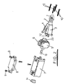
- the assembly comprises a metallic eye 1 for attachment to a rope (not shown). Eye 1 is attached to a shaft (not shown in the view of Figure 1) which passes through a resilient boot 2 into a first housing section 3. Housing 3 defines a window provided with a transparent cover 4 to allow the observation of the movement of components within the housing 3 through that window. A second housing section 5 receives an actuator camshaft (not shown in the view of Figure 1) which is engaged by a reset knob 6 extending outside the housing 5. Housings 3 and 5 are connected to a third housing section 7 which in use houses a switch assembly of known type (not shown in the view of Figure 1). Switch housing 7 has a lid 8 which is secured in position by bolts 9. The housings 3, 5 and 7 are secured together by bolts 10.
- a resilient plug 11 is provided to block a cable entry port in the switch housing 7.
- cables are pushed through apertures cut in the plug 11 and connected to a switch assembly (not shown in Figure 2) located within the switch housing 7.
- a fork 12 which is axially displaceable with the eye 1 extends from the spring housing 3 to engage in the actuator housing 5.
- a cam follower plunger 13 is positioned between the actuator housing 5 and the switch housing 7 to transmit axial motion between the actuator housing 5 and the switch assembly which in use is mounted within the switch housing 7.
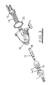
- FIG. 3 shows in greater detail the structure of the spring housing 3.
- the eye 1 defines a groove 14 in which a radially extending lip 15 defined by one end of the resilient boot 2 engages to form a seal.
- the other end of the boot 2 is generally cylindrical and in use engages over a cylindrical extension 16 defined by the spring housing 3.
- the eye 1 is connected by a nut and washer to a threaded end of a shaft 17, the other end of the shaft 17 defining a square flange 18.
- the shaft 17 and fork 12 together define a cam actuator shaft.
- the flange 18 is engaged in the fork 12 such that the two components are axially locked together, a compression spring 19 being arranged around the shaft 17 and between the housing 3 and the fork 12 such that the eye 1 is biased by the spring towards the housing 3.
- a gasket 20 is provided to seal the joint between the spring housing 3 and the actuator housing 5.
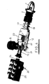
- FIG 4 this illustrates the components received within the three housing sections 3, 5 and 7.
- the reset knob 6 is engaged on one end of a camshaft 21 against which the plunger 13 bears.
- the camshaft 21 is located between two fingers defined by the fork 12, and is acted upon by a first member 22 which is biased against the camshaft 21 by a compression spring located between the first member 22 and a second member 23.
- the member 23 is retained in engagement with the actuator housing 5 ( Figure 2) as described in greater detail below.
- the plunger 13 is located adjacent an actuating plunger 24 of a switch assembly 25 which in use is secured within the switch housing 7 ( Figure 2) by bolts 26.
- One end of the fork defines a rectangular slot 27 into which the square flange 18 mounted on the end of the shaft 17 can be slipped so that the shaft 17 is received within an open sided bore 28.
- those two components can be inter-engaged so as to move in the axial direction as a single body.
- an arrowhead shaped projection 29 is defined, that projection being positioned so as be visible beneath the window 4 (see Figure 1).
- the other end of the fork supports two arms defining abutment surfaces 30, 31, 32a and 32b which are significant to the control of the rotation of the camshaft.
- the first abutment surface 30 acts to apply a force to the camshaft when the shaft 17 ( Figure 4) is moved to the right in Figure 4, the second abutment surface 31 applies a force to the camshaft when the shaft 17 moves to the left in Figure 4, and the further abutment surface 32a obstructs rotation of the camshaft in the event that the camshaft has been displaced as the result of shaft 17 being moved to the left in Figure 4 and not pulled back, for example by tightening a rope attached to the eye 1.
- the further abutment surface 32b serves a similar purpose when the shaft 17 has been displaced in the opposite direction.
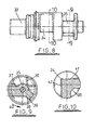
- the camshaft 21 is in three sections, that is a head 33 onto which the reset knob 6 ( Figures 1, 4 and 11) is engaged, a central section defining an edge 34 facing the spring biased member 22 ( Figure 4), and a base section defining a central hub 35.
- Figure 9 is a section through the base section showing a recess 36 which in the orientation shown in Figure 4 is aligned to receive the end of the plunger 13.
- Projecting from the hub 35 are two cams defining surfaces 37 and 38.
- the surface 37 faces the surface 31 defined by the fork
- the surface 38 faces the surface 30 defined by the fork.
- the surfaces 30 and 31 are offset in the axial direction such that an axial displacement of the fork can to a small extent be accommodated without any force being applied to the camshaft 21.
- the surface 38 extends from a comer 39, that comer being intended to pass along the surface 32a of the fork if the surface 31 on the fork pushes the camshaft 21 so as to cause it to rotate in the direction of arrow 40 in Figure 9.
- this shows the edge 34 on the central section of the camshaft and the recess 36 which receives the switch actuating plunger 13 (Figure 4).
- two flat surfaces 41 and 42 extending at right angles from the edge 34 are each inclined at 45° to the axis of the shaft 17. Pressure is applied to the edge 34 by the spring biased member 22 but no significant torque is applied as the spring force is directed through the axis of rotation of the camshaft 21. If however the camshaft 21 is rotated from the position shown in Figure 4 the camshaft 21 will be driven in rotation as a result of the spring force (which is applied through the edge 34) no longer being directed through the camshaft rotation axis.
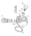
- FIG. 12 shows the camshaft assembly in greater detail.
- the camshaft 21 is inserted into a first bore 43 defined by the actuator housing 5.
- a bush 44 provides a secure support for the base of the camshaft and the reset knob 6 is received in a recessed edge formed around the opening of the bore 43.
- a second bore 45 receives the member 22 which is slidable against the central section of the camshaft under the action of a compression spring 46.
- An end portion of the member 23 is threaded (not shown) so that it can be screwed into a threaded (not shown) section of the bore 45 to maintain an appropriate degree of compression on the spring 46.
- a third bore 47 receives the arms defined by the fork 12 ( Figures 5 to 7) to enable the surfaces 30 and 31 defined by the fork to be positioned facing the surfaces 37 and 38 of the camshaft 21.
- the camshaft 21 On assembly, it is necessary to position the camshaft 21 so that the limb of the fork defining surface 30 can be pushed around the side of the cam from which the surface 37 extends.
- the reset button 6 Only after the fork has been pulled back can the reset button 6 be rotated to the position shown in Figure 4.
- a gasket 48 is provided to form a seal between the actuator housing 5 and the switch housing 7.
Landscapes
- Rotary Switch, Piano Key Switch, And Lever Switch (AREA)
- Mechanisms For Operating Contacts (AREA)
- Push-Button Switches (AREA)
Claims (8)
- Schaltwerk (3, 5, 7), das folgendes umfaßt: ein Gehäuse, einen innerhalb des Gehäuses angebrachten Schalter (25), wobei der Schalter betätigt werden kann, um zwischen einem ersten und einem zweiten Zustand zu schalten, einen innerhalb des Gehäuses zum Drehen um eine vorher festgelegte Nockenachse angebrachten Nocken (21), wobei der Nocken eine Nockenfläche definiert, einen innerhalb des Gehäuses angebrachten Nockenstößel (13), wobei der Nockenstößel (13) derart an der Nockenfläche anliegt, daß ein Drehen des Nockens ein Verschieben des Nockenstößels (13) bewirkt, um den Schalter (25) zu betätigen, und eine innerhalb des Gehäuses in Axialrichtung verschiebbar angeordnete Betätigungswelle (17, 12), wobei die Betätigungswelle (17, 12) derart mechanisch an den Nocken (21) gekoppelt wird, daß ein Verschieben der Welle (17, 12) in Axialrichtung bewirkt, daß sich der Nocken um seine Achse dreht, bei dem die Betätigungswelle (17, 12) in einer Zwischenposition in Axialrichtung angeordnet werden kann, in der sich der Nocken in einer vorher festgelegten Drehposition befindet, so daß der Nockenstößel (13) eine Position hat, in welcher der Schalter den ersten Zustand hat, ein Verschieben der Betätigungswelle (17, 12) aus der Zwischenposition, wenn sich der Nocken (21) in der vorher festgelegten Position befindet, den Nocken (21) derart dreht, daß der Nockenstößel (13) bewirkt, daß der Schalter die zweite Position einnimmt, die Achse des Nockens (21) quer zur Verschiebungsrichtung der Betätigungswelle (17, 12) liegt, dadurch gekennzeichnet, daß die Betätigungswelle (17, 12) eine erste (30) und eine zweite Stoßfläche (31) definiert, wobei die erste Stoßfläche (30) am Nocken anliegt und ein Drehen desselben bewirkt, wenn die Betätigungswelle (17, 12) in der einen Richtung aus der Zwischenposition verschoben wird, und die zweite Stoßfläche (31) am Nocken anliegt und ein Drehen desselben bewirkt, wenn das Stellglied (17, 12) in der anderen Richtung aus der Zwischenposition verschoben wird.
- Schaltwerk nach Anspruch 1, bei dem ein Ende der Betätigungswelle (17, 12) angrenzend an den Nocken einen ersten und einen zweiten Arm definiert, die auf gegenüberliegenden Seiten des Nockens verlaufen, wobei der erste Arm die erste Stoßfläche (30) definiert und der zweite Arm die zweite Stoßfläche (31) definiert.
- Schaltwerk nach Anspruch 2, bei dem jeder Arm eine weitere Stoßfläche (32a, 32b) definiert, wobei die weiteren Stoßflächen ein Drehen des Nockens (21) zu der vorher festgelegten Drehposition verhindern, wenn sich die Betätigungswelle (17, 12) nicht in der Zwischenposition befindet.
- Schaltwerk nach Anspruch 2 oder 3, bei dem die Arme durch ein Gabelelement (12) definiert werden, das von einem Wellenelement (17) getrennt werden kann, aber in Axialrichtung auf demselben arretiert wird, wobei das Gabelelement und das Wellenelement zusammen die Betätigungswelle definieren.
- Schaltwerk nach Anspruch 2, 3 oder 4, bei dem die Drehachse des Nockens (21) mit einer Achse ausgerichtet wird, längs derer die Betätigungswelle (17, 12) verschoben werden kann.
- Schaltwerk nach einem der vorhergehenden Ansprüche, der ein Element (22) umfaßt, das in einer Richtung quer zur Nockenachse gegen den Nocken (21) vorgespannt wird, wobei das an der Seite des Nockens (21) anliegende Element (22) derart geformt wird, daß die Vorspannungsrichtung mit der Achse des Nockens (21) ausgerichtet wird, wenn sich der Nocken in der vorher festgelegten Drehposition befindet, und derart, daß das Element (22) nach einem Wegdrehen des Nockens (21) aus der vorher festgelegten Drehposition ein Drehmoment auf den Nocken (21) ausübt, in einer Richtung, um diese Drehung zu steigern.
- Schaltwerk nach einem der vorhergehenden Ansprüche, bei dem ein Ende des Nockens (21) außerhalb des Gehäuses (3, 5, 7) vorsteht, um zu ermöglichen, daß das Drehmoment manuell auf den Nocken ausgeübt wird.
- Schaltwerk nach einem der vorhergehenden Ansprüche, bei dem das Gehäuse drei Abschnitte umfaßt, von denen ein erster (3) die Betätigungswelle aufnimmt, von denen ein zweiter (5) den Nocken aufnimmt und von denen ein dritte (7) den Schalter aufnimmt, wobei die Betätigungswelle (17, 12) in den zweiten Abschnitt vorsteht und der Nockenstößel (13) vom Schalter in den zweiten Abschnitt vorsteht.
Applications Claiming Priority (2)
| Application Number | Priority Date | Filing Date | Title |
|---|---|---|---|
| GBGB0110712.7A GB0110712D0 (en) | 2001-05-01 | 2001-05-01 | Switch mechanism |
| GB0110712 | 2001-05-01 |
Publications (3)
| Publication Number | Publication Date |
|---|---|
| EP1255262A2 EP1255262A2 (de) | 2002-11-06 |
| EP1255262A3 EP1255262A3 (de) | 2003-01-08 |
| EP1255262B1 true EP1255262B1 (de) | 2004-04-21 |
Family
ID=9913845
Family Applications (1)
| Application Number | Title | Priority Date | Filing Date |
|---|---|---|---|
| EP02251001A Expired - Lifetime EP1255262B1 (de) | 2001-05-01 | 2002-02-14 | Schaltwerk |
Country Status (5)
| Country | Link |
|---|---|
| US (1) | US6646212B2 (de) |
| EP (1) | EP1255262B1 (de) |
| JP (1) | JP4108362B2 (de) |
| DE (1) | DE60200390T2 (de) |
| GB (1) | GB0110712D0 (de) |
Families Citing this family (6)
| Publication number | Priority date | Publication date | Assignee | Title |
|---|---|---|---|---|
| US6705179B1 (en) * | 2000-09-29 | 2004-03-16 | Eja Limited | Modified rope tensioner |
| US7022930B2 (en) | 2003-12-04 | 2006-04-04 | Honeywell International Inc. | Single directional cable actuated emergency stop device |
| GB0407996D0 (en) | 2004-04-07 | 2004-05-12 | Eja Ltd | Switch mechanism with seal |
| GB0620540D0 (en) * | 2006-10-17 | 2006-11-22 | Idem Safety Switches Ltd | Safety switch |
| DE202007013591U1 (de) * | 2007-09-28 | 2008-01-10 | Bernstein Ag | Schnellspanneinrichtung |
| USD751997S1 (en) | 2013-08-08 | 2016-03-22 | Omron Corporation | Box cover for limit switch |
Family Cites Families (6)
| Publication number | Priority date | Publication date | Assignee | Title |
|---|---|---|---|---|
| GB1473497A (en) * | 1974-08-01 | 1977-05-11 | Wheatley B | Control apparatus for electric switches or fluid valves |
| ZA821453B (en) * | 1981-03-09 | 1983-01-26 | Bicc Ltd | Pull key |
| ZA831048B (en) * | 1982-02-19 | 1984-03-28 | Clay Cross Co Ltd | Cam switch mechanism and control device,such as a pullkey,incorporating the same |
| US4658102A (en) * | 1984-09-08 | 1987-04-14 | K. A. Schmersal Gmbh & Co. | Electric switch |
| GB9524297D0 (en) * | 1995-11-28 | 1996-01-31 | Eja Eng Plc | Switch assemblies |
| US5665947A (en) * | 1995-12-20 | 1997-09-09 | Honeywell, Inc. | Cable actuated switching mechanism with mechanical snap action capibility and broken cable monitoring capability |
-
2001
- 2001-05-01 GB GBGB0110712.7A patent/GB0110712D0/en not_active Ceased
-
2002
- 2002-02-14 DE DE60200390T patent/DE60200390T2/de not_active Expired - Lifetime
- 2002-02-14 EP EP02251001A patent/EP1255262B1/de not_active Expired - Lifetime
- 2002-05-01 US US10/137,905 patent/US6646212B2/en not_active Expired - Lifetime
- 2002-05-01 JP JP2002129994A patent/JP4108362B2/ja not_active Expired - Fee Related
Also Published As
| Publication number | Publication date |
|---|---|
| JP4108362B2 (ja) | 2008-06-25 |
| EP1255262A3 (de) | 2003-01-08 |
| EP1255262A2 (de) | 2002-11-06 |
| US6646212B2 (en) | 2003-11-11 |
| JP2002373552A (ja) | 2002-12-26 |
| DE60200390D1 (de) | 2004-05-27 |
| DE60200390T2 (de) | 2005-02-24 |
| US20020175058A1 (en) | 2002-11-28 |
| GB0110712D0 (en) | 2001-06-20 |
Similar Documents
| Publication | Publication Date | Title |
|---|---|---|
| US6365850B1 (en) | Switch assemblies | |
| US20250118505A1 (en) | Linkage Device for Electric Switch Assembly and Electric Switch Assembly Comprising the Linkage Device | |
| US6646212B2 (en) | Switch operating mechanism | |
| US5510583A (en) | Assembly for sequential switching | |
| EP3273462B1 (de) | Kippschalterbetätigungsmechanismus | |
| EP1091470A2 (de) | Automatische Abschaltvorrichtung | |
| US6812419B2 (en) | Enable switch | |
| CN1881495B (zh) | 带有可转动锁定装置的电开关设备的致动器 | |
| US6328357B1 (en) | Trim actuator for use with an exit device | |
| CN1022272C (zh) | 线路保护开关 | |
| CN111512405A (zh) | 电气开关的旋转手柄结构件 | |
| EP0872867B1 (de) | Elektrischer Einheit mit Betätigungseinrichtung für einen Schutzschalter | |
| EP1295306A1 (de) | Mechanische rücksetzvorrichtung für schalter | |
| EP1723839B1 (de) | Kupplungsvorrichtung zum Anschluss von Gartengeräten und dergleichen an eine Antriebseinheit | |
| CA2381237C (en) | Switch actuator | |
| US4331114A (en) | Auxiliary engine stoppage apparatus | |
| ES2109766T3 (es) | Dispositivo de accionamiento manual bloqueable para conectar y desconectar aparatos electricos de maniobra blindados, en especial disyuntores de fuerza. | |
| US6765163B2 (en) | Mechanical reset device for switch | |
| EP0915489B1 (de) | Hebelantrieb für einen Dreistellungsschalter | |
| JP3571260B2 (ja) | 手動機構付きバルブ用アクチュエータ | |
| CN101512696B (zh) | 具有可绕第一旋转轴旋转的第一传递元件的传动单元尤其是操作头 | |
| EP0472477A1 (de) | Betätigungsmechanismus mit Trennvorrichtung für elektrischen Schalter | |
| CN120824139A (zh) | 用于开关设备的操作机构及开关设备组件 | |
| CN121641709A (zh) | 一种操作装置及隔离开关 | |
| HK1017765A1 (en) | Switch device |
Legal Events
| Date | Code | Title | Description |
|---|---|---|---|
| PUAI | Public reference made under article 153(3) epc to a published international application that has entered the european phase |
Free format text: ORIGINAL CODE: 0009012 |
|
| AK | Designated contracting states |
Kind code of ref document: A2 Designated state(s): AT BE CH CY DE DK ES FI FR GB GR IE IT LI LU MC NL PT SE TR |
|
| AX | Request for extension of the european patent |
Free format text: AL;LT;LV;MK;RO;SI |
|
| PUAL | Search report despatched |
Free format text: ORIGINAL CODE: 0009013 |
|
| AK | Designated contracting states |
Kind code of ref document: A3 Designated state(s): AT BE CH CY DE DK ES FI FR GB GR IE IT LI LU MC NL PT SE TR |
|
| AX | Request for extension of the european patent |
Free format text: AL;LT;LV;MK;RO;SI |
|
| 17P | Request for examination filed |
Effective date: 20030303 |
|
| GRAH | Despatch of communication of intention to grant a patent |
Free format text: ORIGINAL CODE: EPIDOS IGRA |
|
| AKX | Designation fees paid |
Designated state(s): DE ES FR GB IT |
|
| GRAS | Grant fee paid |
Free format text: ORIGINAL CODE: EPIDOSNIGR3 |
|
| GRAA | (expected) grant |
Free format text: ORIGINAL CODE: 0009210 |
|
| AK | Designated contracting states |
Kind code of ref document: B1 Designated state(s): DE ES FR GB IT |
|
| REG | Reference to a national code |
Ref country code: GB Ref legal event code: FG4D |
|
| REG | Reference to a national code |
Ref country code: IE Ref legal event code: FG4D |
|
| REF | Corresponds to: |
Ref document number: 60200390 Country of ref document: DE Date of ref document: 20040527 Kind code of ref document: P |
|
| PG25 | Lapsed in a contracting state [announced via postgrant information from national office to epo] |
Ref country code: ES Free format text: LAPSE BECAUSE OF FAILURE TO SUBMIT A TRANSLATION OF THE DESCRIPTION OR TO PAY THE FEE WITHIN THE PRESCRIBED TIME-LIMIT Effective date: 20040801 |
|
| ET | Fr: translation filed | ||
| PLBE | No opposition filed within time limit |
Free format text: ORIGINAL CODE: 0009261 |
|
| STAA | Information on the status of an ep patent application or granted ep patent |
Free format text: STATUS: NO OPPOSITION FILED WITHIN TIME LIMIT |
|
| 26N | No opposition filed |
Effective date: 20050124 |
|
| REG | Reference to a national code |
Ref country code: GB Ref legal event code: 732E Free format text: REGISTERED BETWEEN 20090312 AND 20090318 |
|
| REG | Reference to a national code |
Ref country code: GB Ref legal event code: 732E Free format text: REGISTERED BETWEEN 20120112 AND 20120118 |
|
| REG | Reference to a national code |
Ref country code: FR Ref legal event code: TP Owner name: ROCKWELL AUTOMATION LIMITED, GB Effective date: 20130111 |
|
| REG | Reference to a national code |
Ref country code: FR Ref legal event code: PLFP Year of fee payment: 15 |
|
| REG | Reference to a national code |
Ref country code: FR Ref legal event code: PLFP Year of fee payment: 16 |
|
| REG | Reference to a national code |
Ref country code: FR Ref legal event code: PLFP Year of fee payment: 17 |
|
| PGFP | Annual fee paid to national office [announced via postgrant information from national office to epo] |
Ref country code: GB Payment date: 20200124 Year of fee payment: 19 Ref country code: IT Payment date: 20200121 Year of fee payment: 19 Ref country code: DE Payment date: 20200121 Year of fee payment: 19 |
|
| PGFP | Annual fee paid to national office [announced via postgrant information from national office to epo] |
Ref country code: FR Payment date: 20200122 Year of fee payment: 19 |
|
| REG | Reference to a national code |
Ref country code: DE Ref legal event code: R119 Ref document number: 60200390 Country of ref document: DE |
|
| GBPC | Gb: european patent ceased through non-payment of renewal fee |
Effective date: 20210214 |
|
| PG25 | Lapsed in a contracting state [announced via postgrant information from national office to epo] |
Ref country code: DE Free format text: LAPSE BECAUSE OF NON-PAYMENT OF DUE FEES Effective date: 20210901 Ref country code: FR Free format text: LAPSE BECAUSE OF NON-PAYMENT OF DUE FEES Effective date: 20210228 Ref country code: GB Free format text: LAPSE BECAUSE OF NON-PAYMENT OF DUE FEES Effective date: 20210214 |
|
| PG25 | Lapsed in a contracting state [announced via postgrant information from national office to epo] |
Ref country code: IT Free format text: LAPSE BECAUSE OF NON-PAYMENT OF DUE FEES Effective date: 20210214 |