EP1255328A1 - Hochvolt-Stromschienensystem - Google Patents
Hochvolt-Stromschienensystem Download PDFInfo
- Publication number
- EP1255328A1 EP1255328A1 EP02004831A EP02004831A EP1255328A1 EP 1255328 A1 EP1255328 A1 EP 1255328A1 EP 02004831 A EP02004831 A EP 02004831A EP 02004831 A EP02004831 A EP 02004831A EP 1255328 A1 EP1255328 A1 EP 1255328A1
- Authority
- EP
- European Patent Office
- Prior art keywords
- connector housing
- profile
- busbar system
- voltage busbar
- contact
- Prior art date
- Legal status (The legal status is an assumption and is not a legal conclusion. Google has not performed a legal analysis and makes no representation as to the accuracy of the status listed.)
- Granted
Links
- 239000004020 conductor Substances 0.000 title claims abstract description 26
- 210000002105 tongue Anatomy 0.000 claims abstract description 23
- 238000004873 anchoring Methods 0.000 claims 1
- 238000013459 approach Methods 0.000 description 3
- 238000007688 edging Methods 0.000 description 3
- 238000005516 engineering process Methods 0.000 description 3
- 239000002184 metal Substances 0.000 description 2
- 229910052751 metal Inorganic materials 0.000 description 2
- 239000000725 suspension Substances 0.000 description 2
- 230000007704 transition Effects 0.000 description 2
- RYGMFSIKBFXOCR-UHFFFAOYSA-N Copper Chemical compound [Cu] RYGMFSIKBFXOCR-UHFFFAOYSA-N 0.000 description 1
- 239000000463 material Substances 0.000 description 1
Images


Classifications
-
- H—ELECTRICITY
- H02—GENERATION; CONVERSION OR DISTRIBUTION OF ELECTRIC POWER
- H02G—INSTALLATION OF ELECTRIC CABLES OR LINES, OR OF COMBINED OPTICAL AND ELECTRIC CABLES OR LINES
- H02G5/00—Installations of bus-bars
- H02G5/04—Partially-enclosed installations, e.g. in ducts and adapted for sliding or rolling current collection
-
- H—ELECTRICITY
- H01—ELECTRIC ELEMENTS
- H01R—ELECTRICALLY-CONDUCTIVE CONNECTIONS; STRUCTURAL ASSOCIATIONS OF A PLURALITY OF MUTUALLY-INSULATED ELECTRICAL CONNECTING ELEMENTS; COUPLING DEVICES; CURRENT COLLECTORS
- H01R25/00—Coupling parts adapted for simultaneous co-operation with two or more identical counterparts, e.g. for distributing energy to two or more circuits
- H01R25/14—Rails or bus-bars constructed so that the counterparts can be connected thereto at any point along their length
- H01R25/145—Details, e.g. end pieces or joints
Definitions
- the invention relates to a high-voltage busbar system Profile rails, which contain longitudinal electrical conductors, and with a connector for connecting two rails.
- a high-voltage busbar system is a busbar system that with mains voltage of 230 V, for example is operated, the rails on a current draw allow any places.
- the running in the profile rails However, electrical conductors must be safe to touch be accommodated to endanger persons by the avoid high voltage.
- the earth conductor is metallic with that conductive profile housing connected.
- Busbar systems require the use of connectors that connect two power rails can be electrically and mechanically connected. Usually are such connectors formed as blocks that do not fit into the contour of the profile rails and from engage the outside of the slots in the profile rail to secure the to contact electrical conductor.
- the known connector systems are visually striking. You interrupt the rail system optically.
- Pantographs e.g. spotlights
- rail suspensions installed become.
- the invention has for its object a high-voltage busbar system with connectors to create where the power rails and the connectors are made small and inconspicuous can.
- the connector points a connector housing from which contact tongues protrude, which into the inner parts of the slots of the plastic profiles Profile rails penetrate and the ladder from the inside to contact.
- the ladder By pushing against the inside of the ladder Contact tabs prevent live parts from moving sideways protrude beyond the ladder.
- Connecting the ladder two adjacent rails are made by connectors that from the inside of the profile notes against the ladder to press. This is what usually starts from the outside Avoiding contacting technology, making an elegant transition between the profile rail and connector housing.
- Connector housing can be made very small.
- the contact tongue thus bridges as a one-piece contact element the distance between the conductors to be connected.
- this Connector housing each in a slot of a plastic profile a longitudinal mandrel that goes into the ladder of the adjacent Track stabs.
- the spikes are flush with the Conductors of the subsequent busbars arranged so that they continue this ladder.
- on the thorns, which are arranged in the open slots attack pantographs. This gives the possibility of the connector housing surrounded by a border, so that the transitions to the Profile rails are completely covered.
- the edging can contain an electrical current collector and / or as a mechanical one Rail support may be formed, for example around the Hang profile rails from the ceiling.
- the edging is designed as a pantograph, it can both on the connector as well as on the rails, because the Contacting technology is the same in both cases.
- the edging can also be moved in the longitudinal direction of the rails while being pushed over the connector housing.
- Current collectors e.g. spotlights
- rail suspensions can at any point in the system - also at the connector (there even covering the seams). This has the key Advantage that one of several rail sections and connectors existing existing system optically seamless, through corresponding assembly arrangement, can be designed.
- expansion plugs are provided, each can be used in a longitudinal channel of the profile rail and one show a protruding head from the end of the profile rail, which can be anchored in a longitudinal channel of the connector housing is.
- the expansion anchor is used in the usual expansion anchor technology in the Anchored longitudinal channel of the profile rail. Then will be Head inserted into a longitudinal channel of the connector housing and then bracing takes place, preferably the expansion dowel is pulled towards the connector housing so that the power rail also pulled against the connector housing with force becomes.
- the high-voltage busbar system has busbars that have a metal rail 10 as a supporting component.
- the profile rail 10 consists of an elongated profile body with longitudinally oriented on opposite sides Grooves 11. A longitudinal channel runs between the groove bottoms 12, which is square.
- the profile rail has flat side walls 13 and the openings of the grooves 11 are on the Top and bottom.
- the profile rail has a slim, upright, rectangular outer profile.
- U-shaped plastic profiles 14 In the Grooves 11 of the profile rail are U-shaped plastic profiles 14, each essentially filling the groove 11.
- Each plastic profile 14 has a slot 15.
- the Slots 15 of both plastic profiles are in a common (vertical) level. Each slot 15 contains one in recesses fixed electrical conductor 16.
- the conductor 16 here is a round copper wire.
- the slot 15 divides the slot 15 into an inner part 15a and an outer part open to the outside 15b.
- the inner part 15a is through the plastic profile 14 and the conductor 16 closed circumferentially.
- the outer part 15b of the Slot 15 forms the access opening through which a contact part a (not shown) pantograph with the conductor 16 can come into contact.
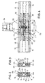
- the connector 18 is used to connect two busbars has a connector housing 19 made of metal, whose profile cross section is shown in Fig. 3.
- the connector housing 19 corresponds to the profile of the profile rail 10. You consists of a section of the profile rail, whereby only subsequently the square longitudinal channel 12 into a round one Longitudinal bore 20 is drilled out.
- the connector housing 19 contains in corresponding grooves 21, which are opposite Open sides, U-shaped plastic profiles 24, which are also formed are like the plastic profiles 14.
- the plastic profiles 24 is a mandrel 26 made of electrical conductive material arranged. The spikes 26 protrude beyond the ends the connector housing 19 with protruding tips 27th
- Contact tongues extend in the longitudinal direction of the connector housing 19 30 made of electrically conductive flat material. This Contact tongues extend through the inner parts of the slots 25 and they protrude from the ends of the connector housing 19.
- In cross bores 31 of the connector housing 19 is one Spring 32 arranged from the inside against the center of the contact tongue 30 presses and thus drives them outside. On in this way the contact tongue 30 is biased outwards.
- the mandrels 26 can also for attacking a pantograph through the slot 25 can be used.
- 4 is a connector housing 19th covering 33 shown.
- This bezel 33 has a length slightly larger than that of the connector housing, so that the joints to the profile rails are covered become.
- the bezel 33 can be attached to a bracket 34 for attachment be provided on a ceiling bracket. In this case, the surround 33 serves as a rail support on which the Rail system is suspended.
- the contact tongue 30 has a recessed central area 35, which extends through the length of the connector housing 19, and outwardly protruding end portions 36, which in the Protrude slots 15 of the profile rail 10.
- the recoil Middle region 35 allows sufficient transverse mobility the contact tongue under the action of the spring 32 so that the end regions 36 are pressed with force against the respective conductor 16 can be.
- a Centering pin 37 is provided, which projects into the spring 32.
- a pin 38 protrudes toward the opposite side a transverse bore 39 of the mandrel 26 protrudes.
- an expansion plug 40 is provided. This has one rectangular shaft 41, which in the longitudinal channel 12 of the rail 10 is inserted and with a longitudinal carving 42 is provided.
- the expansion plug 40 contains a longitudinal one Screw 43 that can be tightened around the slot 42 spread apart and the shaft in the longitudinal channel 12 to tense.
- the expansion dowel 40 then has one on the shaft 41 cylindrical head 44, which in the round longitudinal channel 20 of Connector housing 19 can be inserted.
- a transverse bore 45 is provided through which a screw screwed from the outside into a corresponding transverse bore in the head is.
- the cross holes are arranged so that the Tighten the screw of the expansion anchor that is already in the Profile rail 10 is clamped against the connector housing 19 is pulled so that the busbar is firmly against the connector housing is pressed and held. This tightening can also be done by an eccentric effect.
- the Bezel 33 are placed around the junction.
- the connector housing 19a has a cross section, which is larger than that of the profile rails and it instructs the opposite ends of tubular lugs 50, 51 of generally rectangular cross-section.
- the approaches are each open towards the end and its cavity 52 is the outer contour adapted to the mounting rail so that the mounting rails can be inserted in the appropriate approach 50.51.
- the contact tongues 30 extend through the rectangular ones tubular lugs 50,51 therethrough and protrude beyond them. They are located on the inside of the respective conductor 16 Busbar on.
- Mandrels 26 present in the first embodiment are not provided in the second embodiment.
- the tubular lugs have the advantage that the profile rails 10, which is usually only when assembled to length be cut off, not be cut exactly straight have to. There is a gap even when cutting obliquely from the outside not visible because it disappears in the connector housing 19a.
- the lugs 50, 51 are each on one side with a transverse bore 53 provided in the (not shown) clamping screw sitting.
- the bore 53 is a threaded bore and the The end of the clamping screw presses against the side of the profile rail 10 to prevent them from being pulled out in the connector housing to secure. Therefore, in this embodiment, the Expansion dowel 40 of the first example is not required.
- On the side opposite the bore 53 is located inside of the cavity 52 is a longitudinal projection 55, which in the lateral groove of the profile rail 10 protrudes and an exact Guidance of the profile rail in the approach 50.51 ensures.
- the The area of the bores 53 and the projection 55 are on the sides of the connector housing 19a longitudinal bead-shaped strips 56 provided in this area the strength and Increase stiffness.
- a spring 32 is provided which the contact tongues presses outwards and a sufficient contact pressure on the Head 16 ensures.
- Each of the two tongues is 30 supported on the spring 32 in the manner of a seesaw in the central region.
Landscapes
- Installation Of Bus-Bars (AREA)
- Coupling Device And Connection With Printed Circuit (AREA)
- Superconductors And Manufacturing Methods Therefor (AREA)
- Discharge Heating (AREA)
- Connector Housings Or Holding Contact Members (AREA)
- Emergency Protection Circuit Devices (AREA)
Abstract
Description
Claims (9)
- Hochvolt-Stromschienensystem mit Profilschienen (10), die längslaufende elektrische Leiter (26) enthalten, welche in Schlitze (15) eines Kunststoffprofils (25) eingesetzt sind, wobei jeder Schlitz (15) einen Innenteil (15a) und einen Außenteil (15b) aufweist, die durch den Leiter (16) getrennt sind, und mit einem Verbinder (18) zum elektrischen und mechanischen Verbinden zweier Profilschienen (10),
dadurch gekennzeichnet, dass der Verbinder (18) ein Verbindergehäuse (19;19a) aufweist, aus dem Kontaktzungen (30) vorstehen, welche in die Innenteile (15a) der Schlitze (15) der Kunststoffprofile (14) der anschließenden Profilschienen (10) eindringen und die Leiter (16) von der Innenseite her kontaktieren. - Hochvolt-Stromschienensystem nach Anspruch 1, dadurch gekennzeichnet, dass jede der Kontaktzungen (30) nach entgegengesetzten Seiten aus dem Verbindergehäuse (19;19a) vorsteht und von einer Feder (32) nach außen gedrückt wird.
- Hochvolt-Stromschienensystem nach Anspruch 1 oder 2, dadurch gekennzeichnet, dass das Verbindergehäuse (19) jeweils in einem Schlitz (25) eines Kunststoffprofils (24) einen längslaufenden Dorn (26) aufweist, der mit den Kontaktzungen (30) in Kontakt steht.
- Hochvolt-Stromschienensystem nach Anspruch 3, dadurch gekennzeichnet, dass der Dorn (26) in die Leiter (16) der angrenzenden Stromschienen sticht.
- Hochvolt-Stromschienensystem nach den Ansprüchen 2 und 3, dadurch gekennzeichnet, dass der Dorn (26) einen Anschlag für eine Kontaktzunge (30) bildet.
- Hochvolt-Stromschienensystem nach einem der Ansprüche 1-5, dadurch gekennzeichnet, dass eine das Verbindergehäuse (19) überdeckende Einfassung (33) vorgesehen ist, die als elektrischer Stromabnehmer und/oder als mechanischer Schienenträger ausgebildet ist.
- Hochvolt-Stromschienensystem nach einem der Ansprüche 1-6, dadurch gekennzeichnet, dass ein Spreizdübel (40) vorgesehen ist, der in einen Längskanal (12) der Profilschiene (10) einsetzbar ist und einen aus dem Ende der Profilschiene vorstehendem Kopf (44) aufweist, welcher in einem Längskanal (20) des Verbindergehäuses (19) verankerbar ist.
- Hochvolt-Stromschienensystem nach Anspruch 7, dadurch gekennzeichnet, dass zur Verankerung des Kopfes (44) des Spreizdübels (40) eine Schraube vorgesehen ist, die in eine Querbohrung (45) des Verbindergehäuses (19) derart eingeschraubt ist, dass beim Festschrauben der Spreizdübel (40) zu dem Verbindergehäuse (19) gezogen wird.
- Hochvolt-Stromschienensystem nach Anspruch 1 oder 2, dadurch gekennzeichnet, dass das Verbindergehäuse (19a) nach entgegengesetzten Seiten abstehende rohrförmige Ansätze (50,51) aufweist, in die die Enden der Profilschienen (10) passend einführbar sind.
Applications Claiming Priority (2)
| Application Number | Priority Date | Filing Date | Title |
|---|---|---|---|
| DE20107459U DE20107459U1 (de) | 2001-05-02 | 2001-05-02 | Hochvolt-Stromschienensystem |
| DE20107459U | 2001-05-02 |
Publications (2)
| Publication Number | Publication Date |
|---|---|
| EP1255328A1 true EP1255328A1 (de) | 2002-11-06 |
| EP1255328B1 EP1255328B1 (de) | 2007-05-23 |
Family
ID=7956407
Family Applications (1)
| Application Number | Title | Priority Date | Filing Date |
|---|---|---|---|
| EP02004831A Expired - Lifetime EP1255328B1 (de) | 2001-05-02 | 2002-03-02 | Hochvolt-Stromschienensystem |
Country Status (5)
| Country | Link |
|---|---|
| EP (1) | EP1255328B1 (de) |
| AT (1) | ATE363139T1 (de) |
| DE (2) | DE20107459U1 (de) |
| DK (1) | DK1255328T3 (de) |
| ES (1) | ES2287198T3 (de) |
Families Citing this family (1)
| Publication number | Priority date | Publication date | Assignee | Title |
|---|---|---|---|---|
| RU173798U1 (ru) * | 2017-03-06 | 2017-09-12 | федеральное государственное бюджетное образовательное учреждение высшего образования "Московский государственный технический университет имени Н.Э. Баумана (национальный исследовательский университет)" (МГТУ им. Н.Э. Баумана) | Токосъёмное устройство |
Citations (4)
| Publication number | Priority date | Publication date | Assignee | Title |
|---|---|---|---|---|
| US3622938A (en) * | 1968-12-10 | 1971-11-23 | Matsushita Electric Works Ltd | Electric power distribution device |
| US5336100A (en) * | 1993-09-03 | 1994-08-09 | Juno Lighting, Inc. | Connector for track |
| US6093037A (en) * | 1999-01-28 | 2000-07-25 | Lin; Shan Chaing | Track and connector arrangement |
| WO2001009987A1 (de) * | 1999-07-30 | 2001-02-08 | Andreas Hierzer | Kupplungsstück für stromschienen |
-
2001
- 2001-05-02 DE DE20107459U patent/DE20107459U1/de not_active Expired - Lifetime
-
2002
- 2002-03-02 DK DK02004831T patent/DK1255328T3/da active
- 2002-03-02 EP EP02004831A patent/EP1255328B1/de not_active Expired - Lifetime
- 2002-03-02 AT AT02004831T patent/ATE363139T1/de active
- 2002-03-02 ES ES02004831T patent/ES2287198T3/es not_active Expired - Lifetime
- 2002-03-02 DE DE50210186T patent/DE50210186D1/de not_active Expired - Lifetime
Patent Citations (4)
| Publication number | Priority date | Publication date | Assignee | Title |
|---|---|---|---|---|
| US3622938A (en) * | 1968-12-10 | 1971-11-23 | Matsushita Electric Works Ltd | Electric power distribution device |
| US5336100A (en) * | 1993-09-03 | 1994-08-09 | Juno Lighting, Inc. | Connector for track |
| US6093037A (en) * | 1999-01-28 | 2000-07-25 | Lin; Shan Chaing | Track and connector arrangement |
| WO2001009987A1 (de) * | 1999-07-30 | 2001-02-08 | Andreas Hierzer | Kupplungsstück für stromschienen |
Also Published As
| Publication number | Publication date |
|---|---|
| ES2287198T3 (es) | 2007-12-16 |
| ATE363139T1 (de) | 2007-06-15 |
| DE50210186D1 (de) | 2007-07-05 |
| DE20107459U1 (de) | 2001-07-26 |
| DK1255328T3 (da) | 2007-10-01 |
| EP1255328B1 (de) | 2007-05-23 |
Similar Documents
| Publication | Publication Date | Title |
|---|---|---|
| EP0674375B1 (de) | Lösbare Kupplungsvorrichtung zwischen zwei miteinander fluchtenden elektrischen Leitern | |
| DE4124066A1 (de) | Elektrisches leuchtensystem | |
| EP0795216B1 (de) | Funktionskleinspannungs-stromspeiseeinrichtung | |
| EP0874423B1 (de) | Tragvorrichtung für eine Stromschiene | |
| EP1255328B1 (de) | Hochvolt-Stromschienensystem | |
| EP0871263B1 (de) | Adapter, Stromschiene und Kupplungsvorrichtung | |
| EP3995705B1 (de) | Vorrichtung zum befestigen an einem länglichen element | |
| DE4135391C1 (en) | Cable connector for medium high voltage and high current - has socket with cup-shaped contact element, and cylindrical insulating housing covering inserted cable | |
| DE4008328C2 (de) | ||
| DE19750100C2 (de) | Verbindungsvorrichtung | |
| DE3817133C2 (de) | ||
| DE102007022415A1 (de) | Isolierter Kabelverbinder | |
| DE102016000384B4 (de) | Mehrpoliger elektrischer Verbinder | |
| DE19652401C2 (de) | Stromschienensystem | |
| DE1665349B2 (de) | Hohlkorperförmiger elektrischer Leiter fur hohe Strome und Spannungen | |
| WO2021069363A1 (de) | Stromschiene für leuchten oder elektrische einheiten | |
| DE3007970A1 (de) | Elektrische schaltanlage | |
| DE19710055C2 (de) | Kabelübergangs- und Sicherungskasten | |
| DE3210223A1 (de) | Kniefoermig gestaltete, steckbare kabelgarnitur | |
| DE1765056A1 (de) | Anschlussschiene fuer die Versorgung von Verbrauchern mit elektrischem Strom | |
| DE4202331C2 (de) | Schutzvorrichtung für Kabelsteckteile in T- oder Winkelform | |
| DE10228137B4 (de) | Fixiereinrichtung sowie Schraubverbinder für Kabelleiter mit einer derartigen Fixiereinrichtung | |
| DE3418665C2 (de) | ||
| DE19717649C2 (de) | Vorrichtung zum Anschluß einer Leuchte an zwei voneinander getrennte und übereinander angeordnete stromführende Schienen mit Kreisquerschnitt (Niedervoltstrom) | |
| DE4106785A1 (de) | Installations-kontakt-funktions-system fuer starkstrom und schwachstrom sowie antennen- und fernmeldeanlagen |
Legal Events
| Date | Code | Title | Description |
|---|---|---|---|
| PUAI | Public reference made under article 153(3) epc to a published international application that has entered the european phase |
Free format text: ORIGINAL CODE: 0009012 |
|
| AK | Designated contracting states |
Kind code of ref document: A1 Designated state(s): AT BE CH CY DE DK ES FI FR GB GR IE IT LI LU MC NL PT SE TR |
|
| AX | Request for extension of the european patent |
Free format text: AL;LT;LV;MK;RO;SI |
|
| 17P | Request for examination filed |
Effective date: 20030220 |
|
| AKX | Designation fees paid |
Designated state(s): AT BE CH CY DE DK ES FI FR GB GR IE IT LI LU MC NL PT SE TR |
|
| RAP1 | Party data changed (applicant data changed or rights of an application transferred) |
Owner name: OLIGO LICHTTECHNIK GMBH |
|
| RIN1 | Information on inventor provided before grant (corrected) |
Inventor name: KEFERSTEIN, RALF |
|
| GRAP | Despatch of communication of intention to grant a patent |
Free format text: ORIGINAL CODE: EPIDOSNIGR1 |
|
| GRAS | Grant fee paid |
Free format text: ORIGINAL CODE: EPIDOSNIGR3 |
|
| GRAA | (expected) grant |
Free format text: ORIGINAL CODE: 0009210 |
|
| AK | Designated contracting states |
Kind code of ref document: B1 Designated state(s): AT BE CH CY DE DK ES FI FR GB GR IE IT LI LU MC NL PT SE TR |
|
| PG25 | Lapsed in a contracting state [announced via postgrant information from national office to epo] |
Ref country code: FI Free format text: LAPSE BECAUSE OF FAILURE TO SUBMIT A TRANSLATION OF THE DESCRIPTION OR TO PAY THE FEE WITHIN THE PRESCRIBED TIME-LIMIT Effective date: 20070523 |
|
| REG | Reference to a national code |
Ref country code: GB Ref legal event code: FG4D Free format text: NOT ENGLISH |
|
| REG | Reference to a national code |
Ref country code: CH Ref legal event code: EP |
|
| REG | Reference to a national code |
Ref country code: IE Ref legal event code: FG4D Free format text: LANGUAGE OF EP DOCUMENT: GERMAN |
|
| REG | Reference to a national code |
Ref country code: CH Ref legal event code: NV Representative=s name: ISLER & PEDRAZZINI AG |
|
| REF | Corresponds to: |
Ref document number: 50210186 Country of ref document: DE Date of ref document: 20070705 Kind code of ref document: P |
|
| REG | Reference to a national code |
Ref country code: SE Ref legal event code: TRGR |
|
| GBT | Gb: translation of ep patent filed (gb section 77(6)(a)/1977) |
Effective date: 20070822 |
|
| REG | Reference to a national code |
Ref country code: CH Ref legal event code: PCAR Free format text: ISLER & PEDRAZZINI AG;POSTFACH 1772;8027 ZUERICH (CH) |
|
| REG | Reference to a national code |
Ref country code: DK Ref legal event code: T3 |
|
| ET | Fr: translation filed | ||
| REG | Reference to a national code |
Ref country code: ES Ref legal event code: FG2A Ref document number: 2287198 Country of ref document: ES Kind code of ref document: T3 |
|
| REG | Reference to a national code |
Ref country code: IE Ref legal event code: FD4D |
|
| PG25 | Lapsed in a contracting state [announced via postgrant information from national office to epo] |
Ref country code: PT Free format text: LAPSE BECAUSE OF FAILURE TO SUBMIT A TRANSLATION OF THE DESCRIPTION OR TO PAY THE FEE WITHIN THE PRESCRIBED TIME-LIMIT Effective date: 20071023 Ref country code: IE Free format text: LAPSE BECAUSE OF FAILURE TO SUBMIT A TRANSLATION OF THE DESCRIPTION OR TO PAY THE FEE WITHIN THE PRESCRIBED TIME-LIMIT Effective date: 20070523 |
|
| PLBE | No opposition filed within time limit |
Free format text: ORIGINAL CODE: 0009261 |
|
| STAA | Information on the status of an ep patent application or granted ep patent |
Free format text: STATUS: NO OPPOSITION FILED WITHIN TIME LIMIT |
|
| 26N | No opposition filed |
Effective date: 20080226 |
|
| PG25 | Lapsed in a contracting state [announced via postgrant information from national office to epo] |
Ref country code: GR Free format text: LAPSE BECAUSE OF FAILURE TO SUBMIT A TRANSLATION OF THE DESCRIPTION OR TO PAY THE FEE WITHIN THE PRESCRIBED TIME-LIMIT Effective date: 20070824 |
|
| PG25 | Lapsed in a contracting state [announced via postgrant information from national office to epo] |
Ref country code: MC Free format text: LAPSE BECAUSE OF NON-PAYMENT OF DUE FEES Effective date: 20080331 |
|
| PG25 | Lapsed in a contracting state [announced via postgrant information from national office to epo] |
Ref country code: CY Free format text: LAPSE BECAUSE OF FAILURE TO SUBMIT A TRANSLATION OF THE DESCRIPTION OR TO PAY THE FEE WITHIN THE PRESCRIBED TIME-LIMIT Effective date: 20070523 |
|
| PG25 | Lapsed in a contracting state [announced via postgrant information from national office to epo] |
Ref country code: LU Free format text: LAPSE BECAUSE OF NON-PAYMENT OF DUE FEES Effective date: 20080302 |
|
| PG25 | Lapsed in a contracting state [announced via postgrant information from national office to epo] |
Ref country code: TR Free format text: LAPSE BECAUSE OF FAILURE TO SUBMIT A TRANSLATION OF THE DESCRIPTION OR TO PAY THE FEE WITHIN THE PRESCRIBED TIME-LIMIT Effective date: 20070523 |
|
| REG | Reference to a national code |
Ref country code: DE Ref legal event code: R082 Ref document number: 50210186 Country of ref document: DE Representative=s name: MUELLER-GERBES WAGNER ALBIGER PATENTANWAELTE, DE Ref country code: DE Ref legal event code: R082 Ref document number: 50210186 Country of ref document: DE Representative=s name: WAGNER ALBIGER & PARTNER PATENTANWAELTE MBB, DE |
|
| REG | Reference to a national code |
Ref country code: FR Ref legal event code: PLFP Year of fee payment: 15 |
|
| REG | Reference to a national code |
Ref country code: FR Ref legal event code: PLFP Year of fee payment: 16 |
|
| PGFP | Annual fee paid to national office [announced via postgrant information from national office to epo] |
Ref country code: CH Payment date: 20170327 Year of fee payment: 16 Ref country code: SE Payment date: 20170327 Year of fee payment: 16 Ref country code: FR Payment date: 20170323 Year of fee payment: 16 Ref country code: NL Payment date: 20170323 Year of fee payment: 16 |
|
| PGFP | Annual fee paid to national office [announced via postgrant information from national office to epo] |
Ref country code: BE Payment date: 20170323 Year of fee payment: 16 Ref country code: AT Payment date: 20170322 Year of fee payment: 16 Ref country code: DK Payment date: 20170327 Year of fee payment: 16 Ref country code: GB Payment date: 20170327 Year of fee payment: 16 |
|
| PGFP | Annual fee paid to national office [announced via postgrant information from national office to epo] |
Ref country code: DE Payment date: 20170527 Year of fee payment: 16 |
|
| PGFP | Annual fee paid to national office [announced via postgrant information from national office to epo] |
Ref country code: ES Payment date: 20170323 Year of fee payment: 16 Ref country code: IT Payment date: 20170323 Year of fee payment: 16 |
|
| REG | Reference to a national code |
Ref country code: DE Ref legal event code: R119 Ref document number: 50210186 Country of ref document: DE |
|
| REG | Reference to a national code |
Ref country code: DK Ref legal event code: EBP Effective date: 20180331 |
|
| PG25 | Lapsed in a contracting state [announced via postgrant information from national office to epo] |
Ref country code: SE Free format text: LAPSE BECAUSE OF NON-PAYMENT OF DUE FEES Effective date: 20180303 |
|
| REG | Reference to a national code |
Ref country code: CH Ref legal event code: PL |
|
| REG | Reference to a national code |
Ref country code: NL Ref legal event code: MM Effective date: 20180401 |
|
| REG | Reference to a national code |
Ref country code: AT Ref legal event code: MM01 Ref document number: 363139 Country of ref document: AT Kind code of ref document: T Effective date: 20180302 |
|
| GBPC | Gb: european patent ceased through non-payment of renewal fee |
Effective date: 20180302 |
|
| REG | Reference to a national code |
Ref country code: BE Ref legal event code: MM Effective date: 20180331 |
|
| PG25 | Lapsed in a contracting state [announced via postgrant information from national office to epo] |
Ref country code: NL Free format text: LAPSE BECAUSE OF NON-PAYMENT OF DUE FEES Effective date: 20180401 |
|
| PG25 | Lapsed in a contracting state [announced via postgrant information from national office to epo] |
Ref country code: AT Free format text: LAPSE BECAUSE OF NON-PAYMENT OF DUE FEES Effective date: 20180302 Ref country code: DE Free format text: LAPSE BECAUSE OF NON-PAYMENT OF DUE FEES Effective date: 20181002 |
|
| PG25 | Lapsed in a contracting state [announced via postgrant information from national office to epo] |
Ref country code: LI Free format text: LAPSE BECAUSE OF NON-PAYMENT OF DUE FEES Effective date: 20180331 Ref country code: IT Free format text: LAPSE BECAUSE OF NON-PAYMENT OF DUE FEES Effective date: 20180302 Ref country code: BE Free format text: LAPSE BECAUSE OF NON-PAYMENT OF DUE FEES Effective date: 20180331 Ref country code: GB Free format text: LAPSE BECAUSE OF NON-PAYMENT OF DUE FEES Effective date: 20180302 Ref country code: CH Free format text: LAPSE BECAUSE OF NON-PAYMENT OF DUE FEES Effective date: 20180331 |
|
| PG25 | Lapsed in a contracting state [announced via postgrant information from national office to epo] |
Ref country code: FR Free format text: LAPSE BECAUSE OF NON-PAYMENT OF DUE FEES Effective date: 20180331 |
|
| PG25 | Lapsed in a contracting state [announced via postgrant information from national office to epo] |
Ref country code: DK Free format text: LAPSE BECAUSE OF NON-PAYMENT OF DUE FEES Effective date: 20180331 |
|
| REG | Reference to a national code |
Ref country code: ES Ref legal event code: FD2A Effective date: 20190904 |
|
| PG25 | Lapsed in a contracting state [announced via postgrant information from national office to epo] |
Ref country code: ES Free format text: LAPSE BECAUSE OF NON-PAYMENT OF DUE FEES Effective date: 20180303 |