EP1255328B1 - Hochvolt-Stromschienensystem - Google Patents
Hochvolt-Stromschienensystem Download PDFInfo
- Publication number
- EP1255328B1 EP1255328B1 EP02004831A EP02004831A EP1255328B1 EP 1255328 B1 EP1255328 B1 EP 1255328B1 EP 02004831 A EP02004831 A EP 02004831A EP 02004831 A EP02004831 A EP 02004831A EP 1255328 B1 EP1255328 B1 EP 1255328B1
- Authority
- EP
- European Patent Office
- Prior art keywords
- connector housing
- rail system
- voltage conductor
- profile
- conductor rail
- Prior art date
- Legal status (The legal status is an assumption and is not a legal conclusion. Google has not performed a legal analysis and makes no representation as to the accuracy of the status listed.)
- Expired - Lifetime
Links
- 239000004020 conductor Substances 0.000 title claims abstract description 44
- 210000002105 tongue Anatomy 0.000 claims abstract description 26
- 229920003023 plastic Polymers 0.000 claims abstract description 14
- 239000004033 plastic Substances 0.000 claims abstract description 14
- 238000004873 anchoring Methods 0.000 claims 1
- 239000002184 metal Substances 0.000 description 2
- 229910052751 metal Inorganic materials 0.000 description 2
- 238000000034 method Methods 0.000 description 2
- 239000000725 suspension Substances 0.000 description 2
- 230000007704 transition Effects 0.000 description 2
- RYGMFSIKBFXOCR-UHFFFAOYSA-N Copper Chemical compound [Cu] RYGMFSIKBFXOCR-UHFFFAOYSA-N 0.000 description 1
- 244000089486 Phragmites australis subsp australis Species 0.000 description 1
- 235000014676 Phragmites communis Nutrition 0.000 description 1
- 239000000463 material Substances 0.000 description 1
Images

Classifications
-
- H—ELECTRICITY
- H02—GENERATION; CONVERSION OR DISTRIBUTION OF ELECTRIC POWER
- H02G—INSTALLATION OF ELECTRIC CABLES OR LINES, OR OF COMBINED OPTICAL AND ELECTRIC CABLES OR LINES
- H02G5/00—Installations of bus-bars
- H02G5/04—Partially-enclosed installations, e.g. in ducts and adapted for sliding or rolling current collection
-
- H—ELECTRICITY
- H01—ELECTRIC ELEMENTS
- H01R—ELECTRICALLY-CONDUCTIVE CONNECTIONS; STRUCTURAL ASSOCIATIONS OF A PLURALITY OF MUTUALLY-INSULATED ELECTRICAL CONNECTING ELEMENTS; COUPLING DEVICES; CURRENT COLLECTORS
- H01R25/00—Coupling parts adapted for simultaneous co-operation with two or more identical counterparts, e.g. for distributing energy to two or more circuits
- H01R25/14—Rails or bus-bars constructed so that the counterparts can be connected thereto at any point along their length
- H01R25/145—Details, e.g. end pieces or joints
Definitions
- the invention relates to a high-voltage busbar system with profile rails, which contain longitudinal electrical conductors, and with a connector for connecting two rails.
- a high-voltage busbar system is understood to mean a busbar system which is operated with a mains voltage of, for example, 230 V, the profile rails permitting a current decrease at arbitrary locations.
- the electrical conductors running in the profile rails must be touch-proof be housed in order to avoid a risk to persons due to the high voltage.
- the earth conductor is connected to the metallic conductive profile housing.
- Busbar systems require the use of connectors with which two busbars can be electrically and mechanically connected. Typically, such connectors are formed as blocks that do not fit into the contour of the rails and engage from the outside into the slots of the rail to contact the electrical conductor.
- the known connector systems are visually striking. They optically interrupt the rail system.
- current collectors (eg radiators) or rail suspensions can not be mounted on such connectors.
- busbar systems are e.g. in documents US 6 093 037 A and WO 0109987 A.
- the invention has for its object to provide a high-voltage busbar system with connectors, in which the busbars and the connector can be made small and unobtrusive.
- the connector has contact tongues, which penetrate into the inner parts of the slots of the plastic profiles of the profile rails and contact the conductors from the inside.
- the contact tongues pressing against the conductors from the inside prevent current-carrying parts from projecting laterally beyond the conductors.
- the connection of the conductors of two adjacent rails is effected by connectors which press against the conductors from the inside of the profile rails. This avoids the usually externally applied contacting technique, so that an elegant transition between the profile rail and the connector housing is achieved.
- An essential advantage of the invention is that the Connector housing can be made very small.
- the connector housing can be made small in relation to the rail.
- the connector housing can either be designed flush with the profile rails or as a rectangular tube enclosing the profile rail.
- each of the contact tongues projects out of the connector housing in opposite directions and is pressed outward by a spring.
- the contact tongue thus bridged as a one-piece contact element, the distance between the conductors to be joined.
- the connector housing in each case in a slot of a plastic profile on a longitudinal mandrel which pierces the conductor of the adjacent busbars.
- the mandrels are flush with the conductors of the subsequent busbars so that they continue these conductors.
- the thorns which are arranged in the open slots can attack current collectors. This makes it possible to surround the connector housing with a skirt, so that the transitions to the rails are completely covered.
- the enclosure may include an electrical current collector and / or be designed as a mechanical rail support, for example, to hang the rails on the ceiling.
- the enclosure is designed as a current collector, it can be attached to both the connector and the rails, as the Contacting technology is the same in both cases.
- the enclosure can also be moved in the longitudinal direction of the rails and thereby pushed over the connection housing.
- Current collectors eg spotlights
- rail suspensions can be positioned anywhere on the system - including the connector (even covering the seam there). This has the decisive advantage that a complete system consisting of several rail sections and connectors can be designed optically seamless, with the appropriate mounting arrangement.
- expansion dowel For mechanical attachment of the adjacent rails to the connector housing expansion dowel are provided, each of which can be inserted in a longitudinal channel of the rail and have a projecting from the end of the rail head, which is anchored in a longitudinal channel of the connector housing.
- the expansion anchor is anchored in conventional expansion dowel technique in the longitudinal channel of the rail. Subsequently, its head is inserted into a longitudinal channel of the connector housing and then a tension, wherein preferably the expansion dowel is attracted to the connector housing, so that the busbar is also pulled with force against the connector housing.
- the high-voltage busbar system has busbars, which have a profiled rail 10 made of metal as a supporting component.
- the profiled rail 10 consists of an elongated profile body with longitudinal grooves 11 directed towards opposite sides. Between the groove bottoms runs a longitudinal channel 12 which is square.
- the rail has flat side walls 13 and the openings of the grooves 11 are located at the top and at the bottom.
- the profile rail has a slim, upright, rectangular outer profile.
- U-shaped plastic profiles 14 In the grooves 11 of the rail are U-shaped plastic profiles 14, each of which fill the groove 11 substantially.
- Each plastic profile 14 has a slot 15.
- the slots 15 of both plastic profiles lie in a common (vertical) level.
- Each slot 15 includes a fixed in recesses electrical conductor 16.
- the conductor 16 is here a round copper wire.
- the slot 15 divides the slot 15 into an inner part 15a and an outer part 15b which is open towards the outside.
- the inner part 15a is circumferentially closed by the plastic profile 14 and the conductor 16.
- the outer portion 15b of the slot 15 forms the access opening through which a contact portion of a pantograph (not shown) may come into contact with the conductor 16.
- the connector 18 For connecting two bus bars of the connector 18 is used.
- This has a metal existing connector housing 19, the profile cross-section in Fig. 3 is shown. It consists of a portion of the rail, wherein only subsequently the square longitudinal channel 12 is drilled to a round longitudinal bore 20.
- the connector housing 19 includes in corresponding grooves 21 which open to opposite sides, U-shaped plastic profiles 24 which are formed as well as the plastic profiles 14.
- U-shaped plastic profiles 24 which are formed as well as the plastic profiles 14.
- In the slots 25 of the plastic profiles 24 each have a mandrel 26 is disposed of electrically conductive material. The mandrels 26 project beyond the ends of the connector housing 19 with protruding tips 27.
- contact tongues 30 extend from electrically conductive flat material. These contact tongues extend through the internal parts of the slots 25 and protrude out of the ends of the connector housing 19.
- a spring 32 is in each case arranged, which presses from the inside against the center of the contact tongue 30 and thus drives them to the outside. In this way, the contact tongue 30 is biased outwards.
- the protruding parts of the contact tongues from the connector housing 19 30 are introduced when attaching the rail 10 to the connector 18 in the inner parts 15 a of the slots 15. Of the springs 32, the contact tongues are pressed against the conductors 16 from the inside, so that each contact tongue 30 is a contact bridge, which connects the conductors 16 of two busbars together.
- a housing 33 covering the connector housing 19 is shown.
- This enclosure 33 has a length which is slightly larger than that of the connector housing, so that the joints are covered to the profile rails.
- the enclosure 33 may be provided with a bracket 34 for attachment to a ceiling mount. In this case, the enclosure 33 serves as a rail support on which the rail system is suspended.
- enclosure 33 with pantographs which engage the spikes 26 and feed a fixed to the enclosure (not shown) light.
- the lateral boundaries of the enclosure lie outside the seams between connector 18 and rails 10, so that these seams are covered by the enclosure 33.
- Fig. 5 shows on an enlarged scale one of the contact tongues 30.
- the contact tongue 30 has a recessed central portion 35 which extends through the length of the connector housing 19, and outwardly projecting end portions 36 which project into the slots 15 of the rail 10.
- the recessed central region 35 allows sufficient transverse mobility the contact tongue under the action of the spring 32, so that the end portions 36 can be pressed with force against the respective conductor 16.
- a centering pin 37 is provided, which projects into the spring 32.
- a pin 38 which projects into a transverse bore 39 of the mandrel 26.
- a expansion anchor 40 is provided. This has a rectangular shaft 41 which is inserted into the longitudinal channel 12 of the rail 10 and is provided with a longitudinal carving 42.
- the expansion anchor 40 includes a longitudinal screw 43 which can be tightened to spread the slot 42 apart and to brace the shaft in the longitudinal channel 12.
- the expansion dowel 40 then has on the shaft 41 a cylindrical head 44 which can be inserted into the round longitudinal channel 20 of the connector housing 19.
- a transverse bore 45 is provided, through which a screw is screwed from the outside into a corresponding transverse bore of the head.
- the cross bores are arranged so that when tightening the screw of the expansion dowel, which is already clamped in the rail 10, is pulled against the connector housing 19, so that the busbar is pressed firmly against the connector housing and held. This tightening can also be done by an eccentric action. Thereafter, the skirt 33 can be wrapped around the joint.
- the connector housing 19a has a cross-section which is larger than that of the profile rails and has at its opposite ends tubular projections 50,51 of generally rectangular cross-section.
- the lugs are each open towards the end and their cavity 52 is adapted to the outer contour of the rail, so that the rails can be inserted fittingly into the respective approach 50,51.
- the contact tongues 30 extend through and extend beyond the rectangular tubular extensions 50,51. They are from the inside to the respective conductor 16 of the busbar.
- Mandrels 26, which are present in the first embodiment, are not provided in the second embodiment.
- the tubular projections have the advantage that the profile rails 10, which are usually cut to length only during assembly, do not have to be cut exactly straight. A gap is not visible even when obliquely cut from the outside, because it disappears in the connector housing 19 a.
- the lugs 50,51 are each provided on one side with a transverse bore 53 in which a (not shown) clamping screw sits.
- the bore 53 is a threaded bore and the clamping screw presses with its end against the side of the rail 10 to secure it in the connector housing against withdrawal. Therefore, in this embodiment, the expansion dowels 40 of the first example are not required.
- On the opposite side of the bore 53 is located in the interior of the cavity 52, a longitudinal projection 55 which projects into the lateral groove of the rail 10 and an exact Guiding the profile rail in the approach 50,51 ensures.
- bead-shaped ledges 56 are provided on the sides of the connector housing 19a to increase the strength and rigidity in this area.
- a spring 32 is provided between the contact tongues 30, which presses the contact tongues outwards and ensures a sufficient contact pressure against the conductors 16.
- Each of the two contact tongues 30 is supported on the spring 32 in the manner of a rocker in the middle region.
Landscapes
- Installation Of Bus-Bars (AREA)
- Connector Housings Or Holding Contact Members (AREA)
- Coupling Device And Connection With Printed Circuit (AREA)
- Emergency Protection Circuit Devices (AREA)
- Superconductors And Manufacturing Methods Therefor (AREA)
- Discharge Heating (AREA)
Description
- Die Erfindung betrifft ein Hochvolt-Stromschienensystem mit Profilschienen, welche längslaufende elektrische Leiter enthalten, und mit einem Verbinder zum Verbinden zweier Profilschienen.
- Unter einem Hochvolt-Stromschienensytem versteht man ein Stromschienensystem, das mit Netzspannung von beispielsweise 230 V betrieben wird, wobei die Profilschienen eine Stromabnahme an beliebigen Stellen zulassen. Die in den Profilschienen verlaufenden elektrischen Leiter müssen allerdings berührungssicher untergebracht sein, um eine Gefährdung von Personen durch die hohe Spannung zu vermeiden. Der Erdleiter ist mit dem metallisch leitenden Profilgehäuse verbunden. Stromschienensysteme erfordern den Einsatz von Verbindern, mit denen zwei Stromschienen elektrisch und mechanisch verbunden werden können. Üblicherweise sind solche Verbinder als Blöcke ausgebildet, die sich nicht in die Kontur der Profilschienen einfügen und von außen her in die Schlitze der Profilschiene eingreifen, um den elektrischen Leiter zu kontaktieren. Die bekannten Verbindersysteme sind optisch auffällig. Sie unterbrechen das Schienensystem optisch. Ferner können an derartigen Verbindern keine Stromabnehmer (z. B. Strahler) oder Schienenaufhängungen montiert werden.
- Bekannte Stromschienensysteme sind z.B. in den Dokumenten US 6 093 037 A und WO 0109987 A offenbart.
- Der Erfindung liegt die Aufgabe zugrunde, ein Hochvolt-Stromschienensystem mit Verbindern zu schaffen, bei dem die Stromschienen und die Verbinder klein und unauffällig gestaltet werden können.
- Die Lösung dieser Aufgabe erfolgt erfindungsgemäß mit den in dem kennzeichnenden Teil des Anspruchs 1 angegebenen Merkmalen. Hiernach weist der Verbinder Kontaktzungen auf, welche in die Innenteile der Schlitze der Kunststoffprofile der Profilschienen eindringen und die Leiter von der Innenseite her kontaktieren. Durch die von innen gegen die Leiter drückenden Kontaktzungen wird verhindert, dass stromführende Teile seitlich über die Leiter hinaus vorstehen. Das Verbinden der Leiter zweier angrenzender Profilschienen erfolgt durch Verbinder, die von der Innenseite der Profilscheine her gegen die Leiter drücken. Damit wird die üblicherweise von außen her ansetzende Kontaktierungstechnik vermieden, so dass ein eleganter Übergang zwischen Profilschiene und Verbindergehäuse erreicht wird. Ein wesentlicher Vorteil der Erfindung besteht darin, dass das Verbindergehäuse sehr klein gestaltet werden kann. Im Falle des Kontaktierens von außen - wie beim Stand der Technik - führen wegen des Berührungsschutzes einzuhaltende Luft- und Kriechstrecken zu großen Abmessungen des Verbindergehäuses. Bei dem Gegenstand der Erfindung liegen dagegen die Kontaktzungen, bezogen auf den elektrischen Leiter zur Innenseite hin, so dass es außen keine relevanten Luft- und Kriechstrecken gibt. Dies hat zur Folge, dass das Verbindergehäuse im Verhältnis zur Profilschiene klein gestaltet werden kann. Das Verbindergehäuse kann entweder bündig mit den Profilschienen gestaltet sein oder als ein die Profilschiene umfassendes rechteckiges Rohr.
- Gemäß einer bevorzugten Weiterbildung der Erfindung ragt jede der Kontaktzungen nach entgegengesetzten Seiten aus dem Verbindergehäuse heraus und wird von einer Feder nach außen gedrückt. Die Kontaktzunge überbrückt somit als einstückiges Kontaktelement den Abstand zwischen den zu verbindenden Leitern.
- Gemäß einer bevorzugten Weiterbildung der Erfindung weist das Verbindergehäuse jeweils in einem Schlitz eines Kunststoffprofils einen längslaufenden Dorn auf, der in die Leiter der angrenzenden Stromschienen sticht. Die Dorne sind bündig mit den Leitern der anschließenden Stromschienen angeordnet, so dass sie diese Leiter fortsetzen. Andererseits können an den Dornen, die in den offenen Schlitzen angeordnet sind, Stromabnehmer angreifen. Damit besteht die Möglichkeit, das Verbindergehäuse mit einer Einfassung zu umgeben, so dass die Übergänge zu den Profilschienen vollständig verdeckt sind. Die Einfassung kann einen elektrischen Stromabnehmer enthalten und/oder als mechanischer Schienenträger ausgebildet sein, beispielsweise um die Profilschienen an der Decke aufzuhängen. Wenn die Einfassung als Stromabnehmer ausgebildet ist, kann sie sowohl an den Verbinder als auch an die Profilschienen angesetzt werden, da die Kontaktierungstechnik in beiden Fällen gleich ist. Die Einfassung kann auch in Längsrichtung der Profilschienen verschoben und dabei über das Verbindungsgehäuse hinweggeschoben werden. Stromabnehmer (z. B. Strahler) oder Schienenaufhängungen können an beliebiger Stelle des Systems - also auch am Verbinder (dort sogar nahtüberdeckend) - positioniert werden. Dies hat den entscheidenden Vorteil, dass ein aus mehreren Schienen-Teilstücken und Verbindern bestehendes Gesamtsystem optisch nahtfrei, durch entsprechende Montageanordnung, gestaltet werden kann.
- Zur mechanischen Befestigung der angrenzenden Profilschienen an das Verbindergehäuse sind Spreizdübel vorgesehen, die jeweils in einen Längskanal der Profilschiene einsetzbar sind und einen aus dem Ende der Profilschiene vorstehenden Kopf vorweisen, welcher in einem Längskanal des Verbindergehäuses verankerbar ist. Der Spreizdübel wird in üblicher Spreizdübeltechnik in dem Längskanal der Profilschiene verankert. Anschließend wird sein Kopf in einen Längskanal des Verbindergehäuses eingeschoben und dann erfolgt eine Verspannung, wobei vorzugsweise der Spreizdübel zu dem Verbindergehäuse hingezogen wird, so dass die Stromschiene ebenfalls mit Kraft gegen das Verbindergehäuse gezogen wird.
- Im Folgenden werden unter Bezugnahme auf die Zeichnungen bevorzugte Ausführungsbeispiele der Erfindung näher erläutert.
-
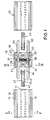
- Fig. 1 eine Explosionsdarstellung einer ersten Ausführungsform des Stromschienensystems,
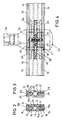
- Fig. 2 einen Schnitt durch die Profilschiene entlang der Linie II-II von Fig. 1,
- Fig. 3 einen Schnitt durch das Verbindergehäuse entlang der Linie III-III von Fig. 1,
- Fig. 4 die Verbindungsstelle des in Fig. 1 dargestellten Systems im montierten Zustand,
- Fig. 5 eine vergrößerte Darstellung einer Kontaktzunge,
- Fig. 6 eine vergrößerte Darstellung eines Dornes des Verbinders,
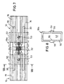
- Fig. 7 die Verbindungsstelle eines weiteren Ausführungsbeispiels, bei dem das Verbindergehäuse an seinen beiden Enden rohrförmige Ansätze aufweist, welche die jeweilige Profilschiene übergreifen, und
- Fig. 8 eine Ansicht des Verbindergehäuses aus Richtung der Pfeile VIII-VIII von Figur 7.
- Das Hochvolt-Stromschienensystem weist Stromschienen auf, die als tragenden Bestandteil eine Profilschiene 10 aus Metall haben. Die Profilschiene 10 besteht aus einem länglichen Profilkörper mit nach entgegengesetzten Seiten gerichteten längslaufenden Nuten 11. Zwischen den Nutböden verläuft ein Längskanal 12, der quadratisch ist. Die Profilschiene hat ebene Seitenwände 13 und die Öffnungen der Nuten 11 befinden sich an der Oberseite und an der Unterseite. Die Profilschiene hat ein schlankes, aufrecht stehendes, rechteckiges Außenprofil. In den Nuten 11 der Profilschiene befinden sich U-förmige Kunststoffprofile 14, die jeweils die Nut 11 im Wesentlichen ausfüllen. Jedes Kunststoffprofil 14 weist einen Schlitz 15 auf. Die Schlitze 15 beider Kunststoffprofile liegen in einer gemeinsamen (vertikalen) Ebene. Jeder Schlitz 15 enthält einen in Rastausnehmungen fixierten elektrischen Leiter 16. Der Leiter 16 ist hier ein runder Kupferdraht. Er unterteilt den Schlitz 15 in einen Innenteil 15a und einen nach außen offenen Außenteil 15b. Der Innenteil 15a ist durch das Kunststoffprofil 14 und den Leiter 16 umfangsmäßig geschlossen. Der Außenteil 15b des Schlitzes 15 bildet die Zugangsöffnung, durch die ein Kontaktteil eines (nicht dargestellten) Stromabnehmers mit dem Leiter 16 in Kontakt kommen kann.
- Zum Verbinden zweier Stromschienen dient der Verbinder 18. Dieser weist ein aus Metall bestehendes Verbindergehäuse 19 auf, dessen Profilquerschnitt in Fig. 3 dargestellt ist. Das Verbindergehäuse 19 entspricht dem Profil der Profilschiene 10. Sie besteht aus einem Abschnitt der Profilschiene, wobei lediglich nachträglich der quadratische Längskanal 12 zu einer runden Längsbohrung 20 aufgebohrt ist. Das Verbindergehäuse 19 enthält in entsprechenden Nuten 21, die sich nach entgegengesetzten Seiten öffnen, U-förmige Kunststoffprofile 24, die ebenso ausgebildet sind wie die Kunststoffprofile 14. In den Schlitzen 25 der Kunststoffprofile 24 ist jeweils ein Dorn 26 aus elektrisch leitendem Material angeordnet. Die Dorne 26 überragen die Enden des Verbindergehäuses 19 mit vorstehenden Spitzen 27.
- In Längsrichtung des Verbindergehäuses 19 erstrecken sich Kontaktzungen 30 aus elektrisch leitendem flachen Material. Diese Kontaktzungen erstrecken sich durch die Innenteile der Schlitze 25 und sie ragen aus den Enden des Verbindergehäuses 19 heraus. In Querbohrungen 31 des Verbindergehäuses 19 ist jeweils eine Feder 32 angeordnet, die von innen her gegen die Mitte der Kontaktzunge 30 drückt und diese somit nach außen treibt. Auf diese Weise ist die Kontaktzunge 30 nach außen vorgespannt. Die aus dem Verbindergehäuse 19 vorstehenden Teile der Kontaktzungen 30 werden beim Ansetzen der Profilschiene 10 an den Verbinder 18 in die Innenteile 15a der Schlitze 15 eingeführt. Von den Federn 32 werden die Kontaktzungen von innen her gegen die Leiter 16 gedrückt, so dass jede Kontaktzunge 30 eine Kontaktbrücke darstellt, welche die Leiter 16 zweier Stromschienen miteinander verbindet.
- Beim Andrücken der Profilschienen 10 an das Verbindergehäuse 19 dringen die Spitzen 27 der Dorne in die Enden der Leiter 16 ein. Dadurch wird eine zusätzliche elektrische Verbindung der Leiter 16 beider Stromschienen bewirkt. Die Dorne 26 können ferner für das Angreifen eines Stromabnehmers durch den Schlitz 25 benutzt werden. In Fig. 4 ist eine das Verbindergehäuse 19 überdeckende Einfassung 33 dargestellt. Diese Einfassung 33 hat eine Länge, die etwas größer ist als diejenige des Verbindergehäuses, so dass die Stoßstellen zu den Profilschienen überdeckt werden. Die Einfassung 33 kann mit einer Halterung 34 zur Befestigung an einer Deckenhalterung versehen sein. In diesem Fall dient die Einfassung 33 als Schienenträger, an dem das Schienensystem aufgehängt ist. Es ist aber auch möglich, die Einfassung 33 mit Stromabnehmern auszubilden, die an den Dornen 26 angreifen und eine an der Einfassung befestigte (nicht dargestellte) Leuchte speisen. Die seitlichen Begrenzungen der Einfassung liegen außerhalb der Nahtstellen zwischen Verbinder 18 und Profilschienen 10, so dass diese Nahtstellen von der Einfassung 33 verdeckt werden.
- Fig. 5 zeigt in vergrößertem Maßstab eine der Kontaktzungen 30. Die Kontaktzunge 30 hat einen zurückspringenden Mittelbereich 35, der sich durch die Länge des Verbindergehäuses 19 erstreckt, und nach außen vorstehende Endbereiche 36, die in die Schlitze 15 der Profilschiene 10 hineinragen. Der zurückspringende Mittelbereich 35 erlaubt eine ausreichende Querbeweglichkeit der Kontaktzunge unter der Wirkung der Feder 32, so dass die Endbereiche 36 mit Kraft gegen den jeweiligen Leiter 16 gedrückt werden können.
- Im Mittelbereich der langgestreckten Kontaktzunge 30 ist ein Zentrierzapfen 37 vorgesehen, der in die Feder 32 hineinragt. Zur entgegengesetzten Seite hin steht ein Zapfen 38 ab, der in eine Querbohrung 39 des Dornes 26 hineinragt.
- Zur Erzielung einer hohen mechanischen Stabilität der Verbindung ist ein Spreizdübel 40 vorgesehen. Dieser weist einen rechteckigen Schaft 41 auf, der in den Längskanal 12 der Profilschiene 10 eingeschoben wird und mit einem Längsschnitz 42 versehen ist. Der Spreizdübel 40 enthält eine längslaufende Schraube 43, die festgezogen werden kann, um den Schlitz 42 auseinander zu spreizen und den Schaft im Längskanal 12 zu verspannen.
- Der Spreizdübel 40 weist anschließend an den Schaft 41 einen zylindrischen Kopf 44 auf, der in den runden Längskanal 20 des Verbindergehäuses 19 eingeführt werden kann. An diesem Längskanal ist eine Querbohrung 45 vorgesehen, durch die eine Schraube von außen in eine entsprechende Querbohrung des Kopfes eingeschraubt ist. Die Querbohrungen sind so angeordnet, dass beim Festziehen der Schraube der Spreizdübel, der bereits in der Profilschiene 10 festgeklemmt ist, gegen das Verbindergehäuse 19 gezogen wird, so dass die Stromschiene fest gegen das Verbindergehäuse gedrückt und festgehalten wird. Dieses Festziehen kann auch durch eine Exzenterwirkung erfolgen. Danach kann die Einfassung 33 um die Verbindungsstelle herumgelegt werden.
- Bei dem Ausführungsbeispiel der Figuren 7 und 8 sind die gleichen Profilschienen 10 vorgesehen wie bei dem ersten Ausführungsbeispiel. Das Verbindergehäuse 19a hat einen Querschnitt, der größer ist als derjenige der Profilschienen und es weist an den einander entgegengesetzten Enden rohrförmige Ansätze 50,51 von generell rechteckigem Querschnitt auf. Die Ansätze sind jeweils zum Ende hin offen und ihr Hohlraum 52 ist der Außenkontur der Profilschiene angepasst, so dass die Profilschienen passend in den jeweiligen Ansatz 50,51 eingeschoben werden können.
- Die Kontaktzungen 30 erstrecken sich durch die rechteckigen rohrförmigen Ansätze 50,51 hindurch und stehen über diese hinaus. Sie liegen von innen her an dem jeweiligen Leiter 16 der Stromschiene an.
- Dorne 26, die bei dem ersten Ausführungsbeispiel vorhanden sind, sind bei dem zweiten Ausführungsbeispiel nicht vorgesehen. Die rohrförmigen Ansätze haben den Vorteil, dass die Profilschienen 10, die in der Regel erst bei der Montage auf Länge abgeschnitten werden, nicht exakt gerade abgeschnitten sein müssen. Ein Spalt ist auch bei schrägem Abschneiden von außen nicht sichtbar, weil er in dem Verbindergehäuse 19a verschwindet.
- Die Ansätze 50,51 sind auf einer Seite jeweils mit einer Querbohrung 53 versehen, in der eine (nicht dargestellte) Klemmschraube sitzt. Die Bohrung 53 ist eine Gewindebohrung und die Klemmschraube drückt mit ihrem Ende gegen die Seite der Profilschiene 10, um diese in dem Verbindergehäuse gegen Herausziehen zu sichern. Daher sind bei diesem Ausführungsbeispiel die Spreizdübel 40 des ersten Beispiels nicht erforderlich. Auf der der Bohrung 53 gegenüberliegenden Seite befindet sich im Inneren des Hohlraums 52 ein längslaufender Vorsprung 55, der in die seitliche Nut der Profilschiene 10 hineinragt und eine exakte Führung der Profilschiene im Ansatz 50,51 sicherstellt. Im Bereich der Bohrungen 53 und des Vorsprungs 55 sind an den Seiten des Verbindergehäuses 19a längslaufende wulstförmige Leisten 56 vorgesehen, um in diesem Bereich die Festigkeit und Steifigkeit zu erhöhen.
- Auch bei dem zweiten Ausführungsbeispiel ist zwischen den Kontaktzungen 30 eine Feder 32 vorgesehen, die die Kontaktzungen nach außen drückt und einen hinreichenden Anpressdruck an die Leiter 16 sicherstellt. Jede der beiden Kontaktzungen 30 ist nach Art einer Wippe im Mittelbereich an der Feder 32 abgestützt.
Claims (9)
- Hochvolt-Stromschienensystem mit Profilschienen (10), die längslaufende elektrische Leiter (16) enthalten, welche in Schlitze (15) eines Kunststoffprofils (14) eingesetzt sind, wobei jeder Schlitz (15) einen Innenteil (15a) und einen Außenteil (15b) aufweist, die durch den Leiter (16) getrennt sind, und mit einem Verbinder (18) zum elektrischen und mechanischen Verbinden zweier Profilschienen (10), wobei der Verbinder (18) ein Verbindergehäuse (19;19a) aufweist, aus dem Kontaktzungen (30) vorstehen, dadurch gekennzeichnet, dass die Kontaktzungen (30) in die Innenteile (15a) der Schlitze (15) der Kunststoffprofile (14) der anschließenden Profilschienen (10) eindringen und die Leiter (16) von der Innenseite her kontaktieren.
- Hochvolt-Stromschienensystem nach Anspruch 1, dadurch gekennzeichnet, dass jede der Kontaktzungen (30) nach entgegengesetzten Seiten aus dem Verbindergehäuse (19;19a) vorsteht und von einer Feder (32) nach außen gedrückt wird.
- Hochvolt-Stromschienensystem nach Anspruch 1 oder 2, dadurch gekennzeichnet, dass das Verbindergehäuse (19) jeweils in einem Schlitz (25) eines Kunststoffprofils (24) einen längslaufenden Dorn (26) aufweist, der mit den Kontaktzungen (30) in Kontakt steht.
- Hochvolt-Stromschienensystem nach Anspruch 3, dadurch gekennzeichnet, dass der Dorn (26) in die Leiter (16) der angrenzenden Stromschienen sticht.
- Hochvolt-Stromschienensystem nach den Ansprüchen 2 und 3, dadurch gekennzeichnet, dass der Dorn (26) einen Anschlag für eine Kontaktzunge (30) bildet.
- Hochvolt-Stromschienensystem nach einem der Ansprüche 1 - 5, dadurch gekennzeichnet, dass eine das Verbindergehäuse (19) überdeckende Einfassung (33) vorgesehen ist, die als elektrischer Stromabnehmer und/oder als mechanischer Schienenträger ausgebildet ist.
- Hochvolt-Stromschienensystem nach einem der Ansprüche 1 - 6, dadurch gekennzeichnet, dass ein Spreizdübel (40) vorgesehen ist, der in einen Längskanal (12) der Profilschiene (10) einsetzbar ist und einen aus dem Ende der Profilschiene vorstehendem Kopf (44) aufweist, welcher in einem Längskanal (20) des Verbindergehäuses (19) verankerbar ist.
- Hochvolt-Stromschienensystem nach Anspruch 7, dadurch gekennzeichnet, dass zur Verankerung des Kopfes (44) des Spreizdübels (40) eine Schraube vorgesehen ist, die in eine Querbohrung (45) des Verbindergehäuses (19) derart eingeschraubt ist, dass beim Festschrauben der Spreizdübel (40) zu dem Verbindergehäuse (19) gezogen wird.
- Hochvolt-Stromschienensystem nach Anspruch 1 oder 2, dadurch gekennzeichnet, dass das Verbindergehäuse (19a) nach entgegengesetzten Seiten abstehende rohrförmige Ansätze (50,51) aufweist, in die die Enden der Profilschienen (10) passend einführbar sind.
Applications Claiming Priority (2)
| Application Number | Priority Date | Filing Date | Title |
|---|---|---|---|
| DE20107459U | 2001-05-02 | ||
| DE20107459U DE20107459U1 (de) | 2001-05-02 | 2001-05-02 | Hochvolt-Stromschienensystem |
Publications (2)
| Publication Number | Publication Date |
|---|---|
| EP1255328A1 EP1255328A1 (de) | 2002-11-06 |
| EP1255328B1 true EP1255328B1 (de) | 2007-05-23 |
Family
ID=7956407
Family Applications (1)
| Application Number | Title | Priority Date | Filing Date |
|---|---|---|---|
| EP02004831A Expired - Lifetime EP1255328B1 (de) | 2001-05-02 | 2002-03-02 | Hochvolt-Stromschienensystem |
Country Status (5)
| Country | Link |
|---|---|
| EP (1) | EP1255328B1 (de) |
| AT (1) | ATE363139T1 (de) |
| DE (2) | DE20107459U1 (de) |
| DK (1) | DK1255328T3 (de) |
| ES (1) | ES2287198T3 (de) |
Cited By (1)
| Publication number | Priority date | Publication date | Assignee | Title |
|---|---|---|---|---|
| RU173798U1 (ru) * | 2017-03-06 | 2017-09-12 | федеральное государственное бюджетное образовательное учреждение высшего образования "Московский государственный технический университет имени Н.Э. Баумана (национальный исследовательский университет)" (МГТУ им. Н.Э. Баумана) | Токосъёмное устройство |
Family Cites Families (4)
| Publication number | Priority date | Publication date | Assignee | Title |
|---|---|---|---|---|
| US3622938A (en) * | 1968-12-10 | 1971-11-23 | Matsushita Electric Works Ltd | Electric power distribution device |
| US5336100A (en) * | 1993-09-03 | 1994-08-09 | Juno Lighting, Inc. | Connector for track |
| US6093037A (en) * | 1999-01-28 | 2000-07-25 | Lin; Shan Chaing | Track and connector arrangement |
| AT408932B (de) * | 1999-07-30 | 2002-04-25 | Hierzer Andreas | Kupplungsstück für stromschienen |
-
2001
- 2001-05-02 DE DE20107459U patent/DE20107459U1/de not_active Expired - Lifetime
-
2002
- 2002-03-02 EP EP02004831A patent/EP1255328B1/de not_active Expired - Lifetime
- 2002-03-02 DK DK02004831T patent/DK1255328T3/da active
- 2002-03-02 DE DE50210186T patent/DE50210186D1/de not_active Expired - Lifetime
- 2002-03-02 AT AT02004831T patent/ATE363139T1/de active
- 2002-03-02 ES ES02004831T patent/ES2287198T3/es not_active Expired - Lifetime
Non-Patent Citations (1)
| Title |
|---|
| None * |
Cited By (1)
| Publication number | Priority date | Publication date | Assignee | Title |
|---|---|---|---|---|
| RU173798U1 (ru) * | 2017-03-06 | 2017-09-12 | федеральное государственное бюджетное образовательное учреждение высшего образования "Московский государственный технический университет имени Н.Э. Баумана (национальный исследовательский университет)" (МГТУ им. Н.Э. Баумана) | Токосъёмное устройство |
Also Published As
| Publication number | Publication date |
|---|---|
| ES2287198T3 (es) | 2007-12-16 |
| DK1255328T3 (da) | 2007-10-01 |
| DE20107459U1 (de) | 2001-07-26 |
| EP1255328A1 (de) | 2002-11-06 |
| DE50210186D1 (de) | 2007-07-05 |
| ATE363139T1 (de) | 2007-06-15 |
Similar Documents
| Publication | Publication Date | Title |
|---|---|---|
| EP4042525A1 (de) | Stromschiene für leuchten oder elektrische einheiten | |
| EP0291989B1 (de) | Niedervolt-Stromschiene | |
| DE4124066A1 (de) | Elektrisches leuchtensystem | |
| EP0674375A1 (de) | Lösbare Kupplungsvorrichtung zwischen zwei miteinander fluchtenden elektrischen Leitern | |
| EP0874423B1 (de) | Tragvorrichtung für eine Stromschiene | |
| DE4340411A1 (de) | Kabelstecker | |
| AT408162B (de) | Adapter, stromschiene und kupplungsvorrichtung | |
| EP1492199B1 (de) | Fixierungseinrichtung sowie Schraubverbinder mit einer derartigen Fixierungseinrichtung | |
| DE3817133C2 (de) | ||
| DE19750100C2 (de) | Verbindungsvorrichtung | |
| DE29508111U1 (de) | Leistungskontaktierung für ein Stromrichtergerät | |
| EP3995705B1 (de) | Vorrichtung zum befestigen an einem länglichen element | |
| EP1255328A1 (de) | Hochvolt-Stromschienensystem | |
| DE10058736B4 (de) | Vorrichtung zum gleichzeitigen elektrischen Verbinden der Hauptleiter einer Energieversorgungsleitung mit jeweils mindestens einem Abzweigleiter, insbesondere Schraubkompaktklemme | |
| DE10228137B4 (de) | Fixiereinrichtung sowie Schraubverbinder für Kabelleiter mit einer derartigen Fixiereinrichtung | |
| DE3834569A1 (de) | Niedervolt-beleuchtungsvorrichtung | |
| EP0380980B1 (de) | Vakuumschalter | |
| EP1028488B1 (de) | Anschlussklemme für ein elektrisches Installationsgerät | |
| DE3418665C2 (de) | ||
| DE4223419C2 (de) | Elektrische Kupplung | |
| DE4232546C1 (de) | Isolator zur Anordnung eines aus Kunststoff-Fäden und stromführenden Leiterdrähten bestehenden Bandes | |
| DE19544476B4 (de) | Vorrichtung zum Verbinden wenigstens einer rohrförmigen Stromschiene mit einer weiteren Stromschienenanordnung | |
| DE19710055A1 (de) | Kabelübergangs- und Sicherungskasten | |
| DD267844A5 (de) | Anschlussklemmeinrichtung, insbesondere fuer drosseln oder transformatoren | |
| DE10066403B4 (de) | Vorrichtung zum gleichzeitigen elektrischen Verbinden der Hauptleiter einer Energieversorgungsleitung mit jeweils mindestens einem Abzweigleiter, insbesondere Schraubkompaktklemme |
Legal Events
| Date | Code | Title | Description |
|---|---|---|---|
| PUAI | Public reference made under article 153(3) epc to a published international application that has entered the european phase |
Free format text: ORIGINAL CODE: 0009012 |
|
| AK | Designated contracting states |
Kind code of ref document: A1 Designated state(s): AT BE CH CY DE DK ES FI FR GB GR IE IT LI LU MC NL PT SE TR |
|
| AX | Request for extension of the european patent |
Free format text: AL;LT;LV;MK;RO;SI |
|
| 17P | Request for examination filed |
Effective date: 20030220 |
|
| AKX | Designation fees paid |
Designated state(s): AT BE CH CY DE DK ES FI FR GB GR IE IT LI LU MC NL PT SE TR |
|
| RAP1 | Party data changed (applicant data changed or rights of an application transferred) |
Owner name: OLIGO LICHTTECHNIK GMBH |
|
| RIN1 | Information on inventor provided before grant (corrected) |
Inventor name: KEFERSTEIN, RALF |
|
| GRAP | Despatch of communication of intention to grant a patent |
Free format text: ORIGINAL CODE: EPIDOSNIGR1 |
|
| GRAS | Grant fee paid |
Free format text: ORIGINAL CODE: EPIDOSNIGR3 |
|
| GRAA | (expected) grant |
Free format text: ORIGINAL CODE: 0009210 |
|
| AK | Designated contracting states |
Kind code of ref document: B1 Designated state(s): AT BE CH CY DE DK ES FI FR GB GR IE IT LI LU MC NL PT SE TR |
|
| PG25 | Lapsed in a contracting state [announced via postgrant information from national office to epo] |
Ref country code: FI Free format text: LAPSE BECAUSE OF FAILURE TO SUBMIT A TRANSLATION OF THE DESCRIPTION OR TO PAY THE FEE WITHIN THE PRESCRIBED TIME-LIMIT Effective date: 20070523 |
|
| REG | Reference to a national code |
Ref country code: GB Ref legal event code: FG4D Free format text: NOT ENGLISH |
|
| REG | Reference to a national code |
Ref country code: CH Ref legal event code: EP |
|
| REG | Reference to a national code |
Ref country code: IE Ref legal event code: FG4D Free format text: LANGUAGE OF EP DOCUMENT: GERMAN |
|
| REG | Reference to a national code |
Ref country code: CH Ref legal event code: NV Representative=s name: ISLER & PEDRAZZINI AG |
|
| REF | Corresponds to: |
Ref document number: 50210186 Country of ref document: DE Date of ref document: 20070705 Kind code of ref document: P |
|
| REG | Reference to a national code |
Ref country code: SE Ref legal event code: TRGR |
|
| GBT | Gb: translation of ep patent filed (gb section 77(6)(a)/1977) |
Effective date: 20070822 |
|
| REG | Reference to a national code |
Ref country code: CH Ref legal event code: PCAR Free format text: ISLER & PEDRAZZINI AG;POSTFACH 1772;8027 ZUERICH (CH) |
|
| REG | Reference to a national code |
Ref country code: DK Ref legal event code: T3 |
|
| ET | Fr: translation filed | ||
| REG | Reference to a national code |
Ref country code: ES Ref legal event code: FG2A Ref document number: 2287198 Country of ref document: ES Kind code of ref document: T3 |
|
| REG | Reference to a national code |
Ref country code: IE Ref legal event code: FD4D |
|
| PG25 | Lapsed in a contracting state [announced via postgrant information from national office to epo] |
Ref country code: PT Free format text: LAPSE BECAUSE OF FAILURE TO SUBMIT A TRANSLATION OF THE DESCRIPTION OR TO PAY THE FEE WITHIN THE PRESCRIBED TIME-LIMIT Effective date: 20071023 Ref country code: IE Free format text: LAPSE BECAUSE OF FAILURE TO SUBMIT A TRANSLATION OF THE DESCRIPTION OR TO PAY THE FEE WITHIN THE PRESCRIBED TIME-LIMIT Effective date: 20070523 |
|
| PLBE | No opposition filed within time limit |
Free format text: ORIGINAL CODE: 0009261 |
|
| STAA | Information on the status of an ep patent application or granted ep patent |
Free format text: STATUS: NO OPPOSITION FILED WITHIN TIME LIMIT |
|
| 26N | No opposition filed |
Effective date: 20080226 |
|
| PG25 | Lapsed in a contracting state [announced via postgrant information from national office to epo] |
Ref country code: GR Free format text: LAPSE BECAUSE OF FAILURE TO SUBMIT A TRANSLATION OF THE DESCRIPTION OR TO PAY THE FEE WITHIN THE PRESCRIBED TIME-LIMIT Effective date: 20070824 |
|
| PG25 | Lapsed in a contracting state [announced via postgrant information from national office to epo] |
Ref country code: MC Free format text: LAPSE BECAUSE OF NON-PAYMENT OF DUE FEES Effective date: 20080331 |
|
| PG25 | Lapsed in a contracting state [announced via postgrant information from national office to epo] |
Ref country code: CY Free format text: LAPSE BECAUSE OF FAILURE TO SUBMIT A TRANSLATION OF THE DESCRIPTION OR TO PAY THE FEE WITHIN THE PRESCRIBED TIME-LIMIT Effective date: 20070523 |
|
| PG25 | Lapsed in a contracting state [announced via postgrant information from national office to epo] |
Ref country code: LU Free format text: LAPSE BECAUSE OF NON-PAYMENT OF DUE FEES Effective date: 20080302 |
|
| PG25 | Lapsed in a contracting state [announced via postgrant information from national office to epo] |
Ref country code: TR Free format text: LAPSE BECAUSE OF FAILURE TO SUBMIT A TRANSLATION OF THE DESCRIPTION OR TO PAY THE FEE WITHIN THE PRESCRIBED TIME-LIMIT Effective date: 20070523 |
|
| REG | Reference to a national code |
Ref country code: DE Ref legal event code: R082 Ref document number: 50210186 Country of ref document: DE Representative=s name: MUELLER-GERBES WAGNER ALBIGER PATENTANWAELTE, DE Ref country code: DE Ref legal event code: R082 Ref document number: 50210186 Country of ref document: DE Representative=s name: WAGNER ALBIGER & PARTNER PATENTANWAELTE MBB, DE |
|
| REG | Reference to a national code |
Ref country code: FR Ref legal event code: PLFP Year of fee payment: 15 |
|
| REG | Reference to a national code |
Ref country code: FR Ref legal event code: PLFP Year of fee payment: 16 |
|
| PGFP | Annual fee paid to national office [announced via postgrant information from national office to epo] |
Ref country code: CH Payment date: 20170327 Year of fee payment: 16 Ref country code: SE Payment date: 20170327 Year of fee payment: 16 Ref country code: FR Payment date: 20170323 Year of fee payment: 16 Ref country code: NL Payment date: 20170323 Year of fee payment: 16 |
|
| PGFP | Annual fee paid to national office [announced via postgrant information from national office to epo] |
Ref country code: BE Payment date: 20170323 Year of fee payment: 16 Ref country code: AT Payment date: 20170322 Year of fee payment: 16 Ref country code: DK Payment date: 20170327 Year of fee payment: 16 Ref country code: GB Payment date: 20170327 Year of fee payment: 16 |
|
| PGFP | Annual fee paid to national office [announced via postgrant information from national office to epo] |
Ref country code: DE Payment date: 20170527 Year of fee payment: 16 |
|
| PGFP | Annual fee paid to national office [announced via postgrant information from national office to epo] |
Ref country code: ES Payment date: 20170323 Year of fee payment: 16 Ref country code: IT Payment date: 20170323 Year of fee payment: 16 |
|
| REG | Reference to a national code |
Ref country code: DE Ref legal event code: R119 Ref document number: 50210186 Country of ref document: DE |
|
| REG | Reference to a national code |
Ref country code: DK Ref legal event code: EBP Effective date: 20180331 |
|
| PG25 | Lapsed in a contracting state [announced via postgrant information from national office to epo] |
Ref country code: SE Free format text: LAPSE BECAUSE OF NON-PAYMENT OF DUE FEES Effective date: 20180303 |
|
| REG | Reference to a national code |
Ref country code: CH Ref legal event code: PL |
|
| REG | Reference to a national code |
Ref country code: NL Ref legal event code: MM Effective date: 20180401 |
|
| REG | Reference to a national code |
Ref country code: AT Ref legal event code: MM01 Ref document number: 363139 Country of ref document: AT Kind code of ref document: T Effective date: 20180302 |
|
| GBPC | Gb: european patent ceased through non-payment of renewal fee |
Effective date: 20180302 |
|
| REG | Reference to a national code |
Ref country code: BE Ref legal event code: MM Effective date: 20180331 |
|
| PG25 | Lapsed in a contracting state [announced via postgrant information from national office to epo] |
Ref country code: NL Free format text: LAPSE BECAUSE OF NON-PAYMENT OF DUE FEES Effective date: 20180401 |
|
| PG25 | Lapsed in a contracting state [announced via postgrant information from national office to epo] |
Ref country code: AT Free format text: LAPSE BECAUSE OF NON-PAYMENT OF DUE FEES Effective date: 20180302 Ref country code: DE Free format text: LAPSE BECAUSE OF NON-PAYMENT OF DUE FEES Effective date: 20181002 |
|
| PG25 | Lapsed in a contracting state [announced via postgrant information from national office to epo] |
Ref country code: LI Free format text: LAPSE BECAUSE OF NON-PAYMENT OF DUE FEES Effective date: 20180331 Ref country code: IT Free format text: LAPSE BECAUSE OF NON-PAYMENT OF DUE FEES Effective date: 20180302 Ref country code: BE Free format text: LAPSE BECAUSE OF NON-PAYMENT OF DUE FEES Effective date: 20180331 Ref country code: GB Free format text: LAPSE BECAUSE OF NON-PAYMENT OF DUE FEES Effective date: 20180302 Ref country code: CH Free format text: LAPSE BECAUSE OF NON-PAYMENT OF DUE FEES Effective date: 20180331 |
|
| PG25 | Lapsed in a contracting state [announced via postgrant information from national office to epo] |
Ref country code: FR Free format text: LAPSE BECAUSE OF NON-PAYMENT OF DUE FEES Effective date: 20180331 |
|
| PG25 | Lapsed in a contracting state [announced via postgrant information from national office to epo] |
Ref country code: DK Free format text: LAPSE BECAUSE OF NON-PAYMENT OF DUE FEES Effective date: 20180331 |
|
| REG | Reference to a national code |
Ref country code: ES Ref legal event code: FD2A Effective date: 20190904 |
|
| PG25 | Lapsed in a contracting state [announced via postgrant information from national office to epo] |
Ref country code: ES Free format text: LAPSE BECAUSE OF NON-PAYMENT OF DUE FEES Effective date: 20180303 |