EP1256287B1 - Drehzylinder für ein Epilationsgerät - Google Patents
Drehzylinder für ein Epilationsgerät Download PDFInfo
- Publication number
- EP1256287B1 EP1256287B1 EP02017888.5A EP02017888A EP1256287B1 EP 1256287 B1 EP1256287 B1 EP 1256287B1 EP 02017888 A EP02017888 A EP 02017888A EP 1256287 B1 EP1256287 B1 EP 1256287B1
- Authority
- EP
- European Patent Office
- Prior art keywords
- pressure
- clamping element
- rotary cylinder
- pins
- damping disk
- Prior art date
- Legal status (The legal status is an assumption and is not a legal conclusion. Google has not performed a legal analysis and makes no representation as to the accuracy of the status listed.)
- Expired - Lifetime
Links
- 238000013016 damping Methods 0.000 claims abstract description 29
- 239000000463 material Substances 0.000 claims abstract description 7
- 229910000639 Spring steel Inorganic materials 0.000 claims abstract description 4
- 229920002457 flexible plastic Polymers 0.000 claims abstract description 4
- 229920003023 plastic Polymers 0.000 claims abstract description 4
- 239000004033 plastic Substances 0.000 claims abstract description 4
- 239000007769 metal material Substances 0.000 claims 1
- 239000002184 metal Substances 0.000 abstract description 5
- 230000000694 effects Effects 0.000 description 4
- 229910000831 Steel Inorganic materials 0.000 description 2
- 238000001514 detection method Methods 0.000 description 2
- 239000002985 plastic film Substances 0.000 description 2
- 229920006255 plastic film Polymers 0.000 description 2
- 239000010959 steel Substances 0.000 description 2
- 230000004913 activation Effects 0.000 description 1
- 239000000853 adhesive Substances 0.000 description 1
- 230000001070 adhesive effect Effects 0.000 description 1
- 238000003780 insertion Methods 0.000 description 1
- 230000037431 insertion Effects 0.000 description 1
- 238000004519 manufacturing process Methods 0.000 description 1
- 229920000642 polymer Polymers 0.000 description 1
- 239000004576 sand Substances 0.000 description 1
Images


Classifications
-
- A—HUMAN NECESSITIES
- A45—HAND OR TRAVELLING ARTICLES
- A45D—HAIRDRESSING OR SHAVING EQUIPMENT; EQUIPMENT FOR COSMETICS OR COSMETIC TREATMENTS, e.g. FOR MANICURING OR PEDICURING
- A45D26/00—Hair-singeing apparatus; Apparatus for removing superfluous hair, e.g. tweezers
- A45D26/0023—Hair-singeing apparatus; Apparatus for removing superfluous hair, e.g. tweezers with rotating clamping elements
- A45D26/0028—Hair-singeing apparatus; Apparatus for removing superfluous hair, e.g. tweezers with rotating clamping elements with rotating discs or blades
-
- A—HUMAN NECESSITIES
- A45—HAND OR TRAVELLING ARTICLES
- A45D—HAIRDRESSING OR SHAVING EQUIPMENT; EQUIPMENT FOR COSMETICS OR COSMETIC TREATMENTS, e.g. FOR MANICURING OR PEDICURING
- A45D26/00—Hair-singeing apparatus; Apparatus for removing superfluous hair, e.g. tweezers
- A45D2026/008—Details of apparatus for removing superfluous hair
- A45D2026/0085—Details of apparatus for removing superfluous hair with means for reducing noise
Definitions
- the invention relates to a rotary cylinder or a rotary roller for an epilator according to the preamble of claim 1.
- an epilation apparatus which is provided with a rotary cylinder having a plurality of angularly offset from each other pairs of clamping elements.
- the clamping elements are brought in pairs during the rotational movement of the rotary cylinder in the region of a Zupfzone in clamping contact. Hair of a user located between the clamping elements are plucked out by the further rotation of the rotary cylinder.
- the object of the invention is to provide a relation to the hair removal efficient and quiet rotary cylinder for an epilator, which in particular develops less noise than conventional rotary cylinder, but still allows a safe detection and plucking of hair.
- the two pressure pins are actuated by a pressure plate and the damping disc is disposed between the pressure pins and the pressure plate.
- the damping disk consists of a metal, in particular of a spring steel, or of a plastic, in particular of a flexible plastic.
- the damping disk is arranged rotationally fixed relative to the rotary cylinder, while the pressure pins are mounted axially displaceably in the rotating rotary cylinder.
- rotary cylinder for an epilator described.
- the term "rotary cylinder” is used, this part can also have cylindrical, convex or concave or convex structures.
- rotary cylinder is used not only for a continuous rotation but also for an oscillating pivotal movement or partial rotation of the cylinder or the like.
- the rotary cylinder has a plurality of discs 1, which are arranged approximately coaxially and adjacent to each other. In the mutually facing surfaces of the discs 1 each have a groove 2 is introduced, which extends approximately across the surface and approximately through the center of the respective disc 1.
- the grooves 2 adjacent, adjacent discs 1 are arranged to each other such that they give an elongated clamping element receiving space 3 with an approximately rectangular cross-section.
- clamping element receiving space 3 two clamping elements are housed, which extend over the entire length of the clamping element receiving space 3, and which have approximately the width thereof.
- the clamping elements are made of metal and are formed like a leaf spring.
- the clamping elements are inserted into the grooves 2 and are arranged approximately parallel to one another with respect to their main extension plane.
- the two clamping elements face each other and form a pair of clamping elements. In part, the two adjacent clamping elements abut each other.
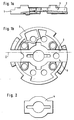
- FIGS. 1a and 1b one of the discs 1 is shown with one of the grooves 2 and the clamping elements receiving space 3 formed therewith.
- the clamping elements are not shown in FIGS. 1a and 1b.
- a washer 4 is shown, which may consist of normal paper and / or sand or sandpaper with a particular fine grain and / or of a plastic film and / or of a moss rubber-like material.
- the washer 4 is formed flat and has the shape of the grooves 2 and the clamping element receiving space.
- FIGS. 3a and 3b the disc 1 is shown with the groove 2 and the clamping element receiving space 3 formed therewith. In the clamping element receiving space 3, the washer 4 is inserted.
- the clamping elements are in the FIGS. 3a and 3b Not shown.
- FIG. 4 is also the disc 1 with the groove 2 and the clamping element receiving space 3 formed therewith.
- the washer 4 is inserted.
- FIG. 4 a movable clamping element 5 and a fixed clamping element 6 are shown.
- On the disc 1 is in the FIG. 4 the next, adjacent arranged disc 1 'attached.
- the two clamping elements 5, 6 are arranged facing each other, each having approximately the dimensions of the clamping element receiving space 3 and are flat, in particular formed like a leaf spring.
- the clamping elements 5, 6 consist for example of steel.
- the disk 1 has a central opening 7, through which an axis for the rotary cylinder can be pushed.
- a projection 8 is arranged on both sides of the opening 7, which is provided with a respective step 9.
- the movable clamping element 5 is provided with a recess 10, with which it can be pushed over the projections 8.
- the movable clamping element 5 is guided laterally by the projections 8, so that it can perform the tilting movement necessary for the clamping operation, regardless of the projections 8 unhindered.
- the disc 1 has an abutment 11 which is formed from two adjoining surfaces 12, 13 of the clamping element receiving space 3, which form an obtuse angle 14 to each other.
- the movable clamping element 5 rests either on one or on the other of the two adjoining surfaces 12, 13 and is thus pivotable about the obtuse angle 14.
- the disc 1 is provided with two openings 15 through which pressure pins 16 extend. With the help of the pressure pins 16 and the tilting bearing or bearing 18, the movable clamping element 5 can be swung back and forth between the two mentioned positions.
- the fixed clamping element 6 is placed on the steps 9 of the projections 8 of the disc 1 and has an opening 17 for the axis of rotation of the rotary cylinder. With the help of the steps 9, the disc 1 'is attached to the disc 1. The fixed clamping element 6 is applied over the entire surface of the disc 1 '.
- the disc 1 has a bearing 18 which faces the counter bearing 11. With the bearing 18, the axis of rotation for the pivoting movement of the free clamping element 5 is fixed. During a pivoting movement of the movable clamping element 5, the free end thereof rests against the free end of the fixed clamping element 6. By the pressure pins 16, the movable clamping element 5 is pressed against the fixed clamping element 6, so that a hair in between is firmly clamped.
- the washer 4 is arranged.
- the movable clamping element 5 is therefore not directly on the surfaces 12, 13 and thus on the anvil 11, but only indirectly via the washer 4th
- the washer 4 represents an intermediate layer which is associated with the movable clamping element 5.
- a game of a few tenths of a milliliter exists. This game is advantageous for the free mobility of the movable clamping element 5.
- the said game is reduced by the insertion of the washer 4.
- the number of joints between the respective components is doubled.
- the movable clamping element 5 executes vibrations in which micro-movements arise. These micro-movements are converted in the joints mentioned by friction into heat (Coulomb friction). The micro-movements are thus damped. This simultaneously represents a noise attenuation. Due to the doubling of the joints by means of the washer 4, therefore, the described effect of joint damping is increased.
- This effect of the joint damping can also be increased by the choice of the material of the washer 4.
- a particularly rough surface of the washer 4 proves to be advantageous.
- Another possibility is to arrange a washer between the fixed clamping element 6 and the disc 1 'and / or between the two clamping elements 5, 6, ie in the region of the bearing 18 and the counter bearing 11.
- the washers it is also possible to produce an intermediate layer in that the surface of the respective clamping element 5, 6 is roughened.
- the disk 1 facing surface of the movable clamping member 5 may be roughened, so that in this way an intermediate layer is formed as part of the clamping member 5, which causes in the same way as the washer 4, an increase in the effect of joint damping.
- FIG. 5a the movable clamping element 5 is shown.
- the recess 10 has an opening through which the axis of the rotary cylinder can be inserted.
- the movable clamping element 5 can be pushed over the projections 8 of the disc 1.
- the tabs 20 can be seen, with which the movable clamping element 5 bears against the bearing 18 of the disc 1 '.
- the two outer layers 21, 23 are made of a metal, in particular of steel.
- the two outer layers may but need not have a different thickness.
- the interposed intermediate layer 22 is made of a polymer, in particular an adhesive.
- movable clamping element 5 represents a zwangs slaughteriges vibration damping system, which is associated with the movable clamping element 5.
- said system resides in one of those components which form the active power flow path in the rotary cylinder.
- the movable clamping element 5 carries out vibrations which lead to shear stresses in the intermediate layer 22.
- the existing vibration energy in the intermediate layer 22 by shear stresses in heat (by internal friction) is converted. This causes a damping of the vibration and thus a reduction of the developed structure-borne sound and / or airborne sound. From the movable clamping element 5 less airborne sound is emitted and introduced less structure-borne noise in adjacent housing parts. Also, less high frequency and therefore unpleasant airborne sound is emitted from the clamping element 5.
- FIGS. 6 and 7 are components that are already related to the FIGS. 1 to 5 have been explained, provided with the same reference numerals. With regard to these components is hereby made to the description of FIGS. 1 to 5 directed.
- FIGS. 1 to 5 existing means for noise reduction, such as the washer 4 or the like, can in the FIGS. 6 and 7 also be present. These funds can also be only partially present or completely eliminated.
- a pressure plate 60 is provided on both sides of the rotary cylinder.
- the pressure plate 60 serves to support the rotary cylinder and determines its axis of rotation.
- the pressure plate 60 is therefore coaxial with the discs 1, 1 'and thus aligned coaxially with the rotary cylinder.
- one side of the rotary cylinder is shown with one of the two pressure plates 60.
- the pressure plate 60 is stationary with respect to the discs 1, 1 'and thus arranged with respect to the rotary cylinder.
- the pressure plate 60 is provided with a pressure roller 61 whose axis of rotation is aligned radially to the axis of rotation of the rotary cylinder.
- FIG. 7 only the axis 62 of the pinch roller 61, but not the pinch roller 61 itself is shown.
- the accommodated in the rotary cylinder pressure pins 16 are actuated by means of the pressure plate 60. This is achieved in that with rotating rotary cylinder, the pressure pins 16 move past the pressure roller 61. During this passing movement, the respective pressure pin 16 is pressed by the pressure roller 61 in the direction of the movable clamping element 5.
- the two pressure pins 16 thus act alternately on the two free ends of the movable clamping element 5. This has the consequence that the clamping element 5 is pivoted back and forth between its two end positions. In this case, the clamping element 5 is always moved by one of the two pressure pins 16 at its one free end in one of the two end positions, while the other pressure pin 16 is thereby pushed back simultaneously from the other free end of the clamping element 5.
- the damping disk 63 consists of a metal, in particular of a spring steel, or of a plastic, in particular of a flexible plastic., Or a plastic film.
- the damping disc 63 is coaxial with the pressure plate 60 and thus aligned coaxially with the rotary cylinder. With the aid of centering pins 64, the damping disk 63 is fixedly coupled to the pressure plate 60, so that the damping disk 63 can not rotate about the axis of rotation of the rotary cylinder.
- the damping disk 63 has a region 65, which due to the fixing pins 64 permanently associated with the pressure roller 61 and there between the pinch roller 61 and the each actuated pressure pin 16 is arranged. Also, the damping plate 63 has a portion 66 which is permanently assigned due to the fixing pins 64 that pressure pin 16, which faces the respective actuated pressure pin 16 and thus the same clamping element 5 is assigned. This region 66 of the damping disk 63 is arranged between this opposing pressure pin 16 and the pressure plate 60.
- the opposing pressure pin 16 is pushed back by the associated free end of the movable clamping element 5. Of the pressure plate 60, the pressure pin 16 is not charged in this position. This has without the damping disk 63 with the result that the pressure pin 16 and thus also the associated free end of the clamping element 5 can move uncontrollably and optionally can be set in vibration.
- the portion 66 of the damper disc 63 is formed such that said opposing pressure pin 16 is loaded by the damper disc 63.
- the pressure pin 16 is pressed continuously against the free end of the clamping element 5.
- the pressure pin 16 thus constantly abuts against the free end of the clamping element 5.
- damping disk 63 By the damping disk 63 is also the driving over the pressure roller (61) by the pressure pins 16 is particularly quiet.
Landscapes
- Braking Arrangements (AREA)
- Holding Or Fastening Of Disk On Rotational Shaft (AREA)
- Harvester Elements (AREA)
- Rolls And Other Rotary Bodies (AREA)
- Clamps And Clips (AREA)
- Shovels (AREA)
- Polishing Bodies And Polishing Tools (AREA)
- Filling Or Discharging Of Gas Storage Vessels (AREA)
- Other Liquid Machine Or Engine Such As Wave Power Use (AREA)
- Road Repair (AREA)
- Auxiliary Devices For Music (AREA)
- Vibration Prevention Devices (AREA)
- Snaps, Bayonet Connections, Set Pins, And Snap Rings (AREA)
Description
- Die Erfindung betrifft einen Drehzylinder oder eine Drehwalze für ein Epilationsgerät nach dem Oberbegriff des Anspruchs 1.
- Aus der internationalen Patentschrift
WO98/05234 - Aufgabe der Erfindung ist es, einen bezüglich der Haarentferung effizienten und leisen Drehzylinder für ein Epilationsgerät zu schaffen, der insbesondere weniger Geräusche als herkömmliche Drehzylinder entwickelt, aber trotzdem ein sicheres Erfassen und Auszupfen von Haaren ermöglicht.
- Diese Aufgabe wird bei einem Drehzylinder der eingangs genannten Art erfindungsgemäß durch die kennzeichnenden Merkmale des Anspruchs 1 gelöst.
- Durch die Zuordnung der Dämpfungsscheibe zu den Druckstiften kann eine besonders effektive und weitreichende Geräuschdämpfung erreicht werden. Insgesamt ist damit eine weitgehende Geräuschminderung erreichbar, die nur einen geringen zusätzlichen Aufwand erforderlich macht.
- Die beiden Druckstifte sind durch eine Andruckplatte betätigbar und die Dämpfungsscheibe ist zwischen den Druckstiften und der Andruckplatte angeordnet.
- Zweckmäßig ist es dabei, wenn die Dämpfungsscheibe aus einem Metall, insbesondere aus einem Federstahl, oder aus einem Kunststoff, insbesondere aus einem flexiblen Kunststoff besteht.
- Die Dämpfungsscheibe ist drehfest gegenüber dem Drehzylinder angeordnet, während die Druckstifte axial verschiebbar im rotierenden Drehzylinder gelagert sind.
- Aus der
EP 0 600 998 B1 ist bereits ein Epilationsgerät bekannt, bei welchem eine geräuschreduzierende Führungsscheibe zwischen einem Druckelement, welches die Klemmelemente trägt, und dessen Betätigungselement vorgesehen ist. Die Führungsscheibe dient jedoch lediglich dem Erzeugen eines sanften Auflaufens des Druckelementes auf den zugeordneten Steuernocken. - Weitere Merkmale, Anwendungsmöglichkeiten und Vorteile der Erfindung ergeben sich aus der nachfolgenden Beschreibung von Ausführungsbeispielen der Erfindung, die in den Figuren der Zeichnung dargestellt sind.
- Figur 1a
- zeigt eine schematische Schnittdarstellung eines Ausführungsbeispiels einer Scheibe eines erfindungsgemäßen Drehzylinders für ein Epilationsgerät entlang der Ebene I der
Figur 1b , - Figur 1b
- zeigt eine schematische Draufsicht auf die Scheibe der
Figur 1a , - Figur 2
- zeigt eine schematische Draufsicht auf eine erfindungsgemäße Unterlegscheibe für die Scheibe der
Figuren 1a und 1b , - Figur 3a
- zeigt eine schematische Schnittdarstellung der Scheibe der
Figuren 1a und 1b und der eingelegten Unterlegscheibe derFigur 2 entlang der Ebene III derFigur 3b , - Figur 3b
- zeigt eine schematische Draufsicht auf die Scheibe und die eingelegte Unterlegscheibe der
Figur 3a , - Figur 4
- zeigt eine vergrößerte Darstellung einer schematischen Schnittdarstellung der Scheibe der
Figuren 1a und 1b und der eingelegten Unterlegscheibe derFigur 2 sowie den Ansteuermechanismus, - Figur 5a
- zeigt eine schematische Draufsicht auf ein Ausführungsbeispiel eines erfindungsgemäßen Klemmelements für den Drehzylinder,
- Figur 5b
- zeigt eine schematische Seitenansicht auf das Klemmelement der
Figur 5a , - Figur 5c
- zeigt eine vergrößerte Darstellung der schematischen Seitenansicht des Klemmelements der
Figur 5a , - Figur 6
- zeigt eine schematische Schnittdarstelltung des Drehzylinders mit einer Andruckplatte, und
- Figur 7
- zeigt eine schematische Perspektivdarstellung der Andruckplatte der
Figur 6 mit einer zugeordneten Dämpfungsscheibe. - In der internationalen Patentschrift
WO98/05234 - Der Drehzylinder weist eine Mehrzahl von Scheiben 1 auf, die etwa koaxial und benachbart zueinander angeordnet sind. In den einander zugewandten Flächen der Scheiben 1 ist jeweils eine Nut 2 eingebracht, die etwa quer über die Fläche und etwa durch den Mittelpunkt der jeweiligen Scheibe 1 verläuft. Die Nuten 2 einander zugewandter, benachbarter Scheiben 1 sind derart zueinander angeordnet, daß sie einen länglichen Klemmelemente-Aufnahmeraum 3 mit einem etwa rechteckigen Querschnitt ergeben.
- In dem Klemmelemente-Aufnahmeraum 3 sind zwei Klemmelemente untergebracht, die sich über die gesamte Länge des Klemmelemente-Aufnahmeraums 3 erstrecken, und die etwa die Breite desselben besitzen. Die Klemmelemente bestehen aus Metall und sind blattfederartig ausgebildet. Die Klemmelemente sind in die Nuten 2 eingelegt und sind bezüglich ihrer Hauptausdehnungsebene etwa parallel zueinander angeordnet. Die beiden Klemmelemente sind einander zugewandt und bilden ein Paar von Klemmelementen. Teilweise liegen die beiden benachbarten Klemmelemente aneinander an.
- In den
Figuren 1a und 1b ist eine der Scheiben 1 mit einer der Nuten 2 und dem damit gebildeten Klemmelemente-Aufnahmeraum 3 dargestellt. Die Klemmelemente sind in den Figuren 1a und 1 b nicht gezeigt. - In der
Figur 2 ist eine Unterlegscheibe 4 dargestellt, die aus normalem Papier und/oder aus Sand- bzw. Schleifpapier mit einer insbesondere feinen Körnung und/oder aus einer Kunststofffolie und/oder aus einem moosgummiartigem Material bestehen kann. Die Unterlegscheibe 4 ist flach ausgebildet und besitzt die Form der Nuten 2 bzw. des Klemmelemente-Aufnahmeraums 3. - In den
Figuren 3a und 3b ist die Scheibe 1 mit der Nut 2 und dem damit gebildeten Klemmelemente-Aufnahmeraum 3 dargestellt. In den Klemmelemente-Aufnahmeraum 3 ist die Unterlegscheibe 4 eingelegt. Die Klemmelemente sind in denFiguren 3a und 3b nicht gezeigt. - In der
Figur 4 ist ebenfalls die Scheibe 1 mit der Nut 2 und dem damit gebildeten Klemmelemente-Aufnahmeraum 3 dargestellt. In den Klemmelemente-Aufnahmeraum 3 ist die Unterlegscheibe 4 eingelegt. Des weiteren sind in derFigur 4 ein bewegliches Klemmelement 5 und ein festes Klemmelement 6 gezeigt. Auf die Scheibe 1 ist in derFigur 4 die nächste, benachbart angeordnete Scheibe 1' aufgesteckt. - Die beiden Klemmelemente 5, 6 sind einander zugewandt angeordnet, besitzen jeweils etwa die Abmessungen des Klemmelemente-Aufnahmeraums 3 und sind flächig, insbesondere blattfederartig ausgebildet. Die Klemmelemente 5, 6 bestehen beispielsweise aus Stahl.
- Die Scheibe 1 weist eine zentrale Öffnung 7 auf, durch die eine Achse für den Drehzylinder hindurchsteckbar ist. In Richtung des Klemmelemente-Aufnahmeraums 3 ist auf beiden Seiten der Öffnung 7 jeweils ein Vorsprung 8 angeordnet, der mit jeweils einer Stufe 9 versehen ist.
- Das bewegliche Klemmelement 5 ist mit einer Ausnehmung 10 versehen, mit der es über die Vorsprünge 8 hinweggeschoben werden kann. Das bewegliche Klemmelement 5 wird durch die Vorsprünge 8 seitlich geführt, so daß es unabhängig von den Vorsprüngen 8 die für den Klemmvorgang notwendige Kippbewegung ungehindert ausführen kann.
- Die Scheibe 1 weist ein Gegenlager 11 auf, das aus zwei aneinander angrenzenden Flächen 12, 13 des Klemmelemente-Aufnahmeraums 3 gebildet wird, die einen stumpfen Winkel 14 zueinander bilden. Das bewegliche Klemmelement 5 liegt entweder auf der einen oder auf der anderen der beiden aneinander angrenzenden Flächen 12, 13 auf und ist damit um den stumpfen Winkel 14 schwenkbar.
- Die Scheibe 1 ist mit zwei Öffnungen 15 versehen, durch die sich Druckstifte 16 erstrecken. Mit Hilfe der Druckstifte 16 und dem Kipplager bzw. Lager 18 kann das bewegliche Klemmelement 5 zwischen den beiden genannten Postitionen hin- und hergeschwenkt werden.
- Das feste Klemmelement 6 ist auf die Stufen 9 der Vorsprünge 8 der Scheibe 1 aufgelegt und weist eine Öffnung 17 für die Drehachse des Drehzylinders auf. Mit Hilfe der Stufen 9 ist die Scheibe 1' auf die Scheibe 1 aufgesteckt. Das feste Klemmelement 6 liegt ganzflächig an der Scheibe 1' an.
- Die Scheibe 1' weist ein Lager 18 auf, das dem Gegenlager 11 zugewandt ist. Mit dem Lager 18 ist die Drehachse für die Schwenkbewegung des freien Klemmelements 5 festgelegt. Bei einer Schwenkbewegung des beweglichen Klemmelements 5 liegt das freie Ende desselben im Bereich des freien Endes des festen Klemmelements 6 an. Durch die Druckstifte 16 wird das bewegliche Klemmelement 5 gegen das feste Klemmelement 6 gedrückt, so daß ein dazwischen befindliches Haar fest eingeklemmt wird.
- Zwischen dem beweglichen Klemmelement 5 und der Scheibe 1 ist die Unterlegscheibe 4 angeordnet. Das bewegliche Klemmelement 5 liegt also nicht unmittelbar an den Flächen 12, 13 und damit an dem Gegenlager 11 an, sondern nur mittelbar über die Unterlegscheibe 4.
- Die Unterlegscheibe 4 stellt eine Zwischenschicht dar, die dem beweglichen Klemmelement 5 zugeordnet ist. An sich ist aus fertigungstechnischen Gründen zwischen dem beweglichen Klemmelement 5 und dem Gegenlager 11 ein Spiel von wenigen Zehntelmillimentern vorhanden. Diese Spiel ist für die freie Beweglichkeit des beweglichen Klemmelements 5 vorteilhaft. Das genannte Spiel wird durch das Einlegen der Unterlegscheibe 4 verringert. Durch eine entsprechende Materialwahl der Unterlegscheibe 4, insbesondere durch eine elastische Ausbildung der Unterlegscheibe 4, und durch eine entsprechende Wahl der Dicke der Unterlegscheibe 4 wird jedoch weiterhin die freie Beweglichkeit des beweglichen Klemmelements 5 aufrecht erhalten werden.
- Durch die Unterlegscheibe 4 wird die Anzahl der Fugen zwischen den betreffenden Bauteilen verdoppelt. Und zwar liegen Fugen vor zwischen dem beweglichen Klemmelement 5 und der Unterlegscheibe 4 sowie zwischen der Unterlegscheibe 4 und dem Gegenlager 11. Das bewegliche Klemmelement 5 führt Schwingungen aus, bei denen Mikrobewegungen entstehen. Diese Mikrobewegungen werden in den genannten Fugen durch Reibung in Wärme (Coulombsche Reibung) umgewandelt. Die Mikrobewegungen werden damit gedämpft. Dies stellt gleichzeitig eine Geräuschdämpfung dar. Durch die Verdoppelung der Fugen mittels der Unterlegscheibe 4 wird deshalb der beschriebene Effekt der Fugendämpfung vergrößert.
- Ebenfalls hat sich gezeigt, daß sich durch den Effekt der Fugendämpfung die hochfrequenten und damit für das menschliche Gehör unangenehmeren Frequenzen verringern.
- Dieser Effekt der Fugendämpfung kann ebenfalls vergrößert werden durch die Wahl des Materials der Unterlegscheibe 4. Insbesondere erweist sich eine besonders rauhe Oberfläche der Unterlegscheibe 4 als vorteilhaft.
- Eine weitere Möglichkeit besteht darin, eine Unterlegscheibe auch zwischen dem festen Klemmelement 6 und der Scheibe 1' und/oder zwischen den beiden Klemmelementen 5, 6, also im Bereich des Lagers 18 bzw. des Gegenlagers 11 anzuordnen.
- Anstelle der Unterlegscheiben ist es ebenfalls möglich, eine Zwischenschicht dadurch zu erzeugen, daß die Oberfläche des jeweiligen Klemmelements 5, 6 aufgerauht wird. So kann die der Scheibe 1 zugewandte Fläche des beweglichen Klemmelements 5 aufgerauht sein, so daß auf diese Weise eine Zwischenschicht als Bestandteil des Klemmelements 5 entsteht, die in gleicher Weise wie die Unterlegscheibe 4 eine Vergrößerung des Effekts der Fugendämpfung bewirkt.
- In der
Figur 5a ist das bewegliche Klemmelement 5 dargestellt. Die Ausnehmung 10 weist eine Öffnung auf, durch die die Achse des Drehzylinders hindurchgesteckt werden kann. Insbesondere mit den Ausnehmungen 19 kann das bewegliche Klemmelement 5 über die Vorsprünge 8 der Scheibe 1 hinweggeschoben werden. Ebenfalls sind aus derFigur 5 die Laschen 20 erkennbar, mit denen das bewegliche Klemmelement 5 an dem Lager 18 der Scheibe 1' anliegt. - Entsprechend den
Figuren 5b und 5c ist das bewegliche Klemmelement 5 aus drei Lagen 21, 22, 23 zusammengesetzt, die fest miteinander verbunden sind. Die beiden äußeren Lagen 21, 23 bestehen aus einem Metall, insbesondere aus Stahl. Die beiden äußeren Lagen können, müssen aber nicht eine unterschiedliche Dicke besitzen. Die dazwischen befindliche Zwischenlage 22 besteht aus einem Polymer, insbesondere einem Klebstoff. - Das in den
Figuren 5a, 5b und 5c dargestellte bewegliche Klemmelement 5 stellt ein zwangsschichtiges Schwingungsdämpfungssystem dar, das dem beweglichen Klemmelement 5 zugeordnet ist. Damit liegt das genannte System in einem derjenigen Bauteile, die den aktiven Kraftflußweg in dem Drehzylinder bilden. - Das bewegliche Klemmelement 5 führt Schwingungen aus, die zu Schubspannungen in der Zwischenlage 22 führen. Damit wird die vorhandene Schwingungsenergie in der Zwischenlage 22 durch Schubspannungen in Wärme (durch innere Reibung) umgewandelt. Dies bewirkt eine Dämpfung der Schwingung und damit auch eine Verminderung des entwickelten Körperschalls und/oder Luftschalls. Von dem beweglichen Klemmelement 5 wird weniger Luftschall abgestrahlt und weniger Körperschall in benachbarte Gehäuseteile eingeleitet. Ebenfalls wird von dem Klemmelement 5 weniger hochfrequenter und damit für das menschliche Gehör unangenehmer Luftschall abgestrahlt.
- Ein weiterer Vorteil des in den
Figuren 5a, 5b und 5c dargestellten beweglichen Klemmelements 5 besteht darin, daß auch das Prellen des Klemmelements 5 vermindert wird. Damit wird das Schließverhalten der Klemmelemente 5, 6 verbessert und ein sicheres Erfassen und Auszupfen von Haaren gewährleistet. - In den
Figuren 6 und7 sind Bauteile, die bereits im Zusammenhang mit denFiguren 1 bis 5 erläutert worden sind, mit gleichen Bezugszeichen versehen. Hinsichtlich dieser Bauteile wird hiermit auf die Beschreibung derFiguren 1 bis 5 verwiesen. - Die in den
Figuren 1 bis 5 vorhandenen Mittel zur Geräuschdämpfung, beispielsweise die Unterlegscheibe 4 oder dergleichen, können bei denFiguren 6 und7 ebenfalls vorhanden sein. Diese Mittel können aber auch nur teilweise vorhanden sein oder ganz entfallen. - Entsprechend der
Figur 4 , so sind auch in denFiguren 6 und7 die Druckstifte 16 dazu vorgesehen, auf das bewegliche Klemmelement 5 einzuwirken. Den beiden freien Enden des Klemmelements 5 ist dabei jeweils einer der Druckstifte 16 zugeordnet. - Auf beiden Seiten des Drehzylinders ist eine Andruckplatte 60 vorgesehen. Die Andruckplatte 60 dient der Lagerung des Drehzylinders und legt dessen Drehachse fest. Die Andruckplatte 60 ist deshalb koaxial zu den Scheiben 1, 1' und damit koaxial zu dem Drehzylinder ausgerichtet. In der
Figur 6 ist eine Seite des Drehzylinders mit einer der beiden Andruckplatten 60 dargestellt. - Die Andruckplatte 60 ist ortsfest in Bezug auf die Scheiben 1, 1' und damit in Bezug auf den Drehzylinder angeordnet. Die Andruckplatte 60 ist mit einer Andruckrolle 61 versehen, deren Drehachse radial zur Drehachse des Drehzylinders ausgerichtet ist. In der
Figur 7 ist nur die Achse 62 der Andruckrolle 61, jedoch nicht die Andruckrolle 61 selbst dargestellt. - Die in dem Drehzylinder untergebrachten Druckstifte 16 werden mit Hilfe der Andruckplatte 60 betätigt. Dies wird dadurch erreicht, daß bei rotierendem Drehzylinder sich die Druckstifte 16 an der Andruckrolle 61 vorbeibewegen. Bei diesem Vorbeibewegen wird der jeweilige Druckstift 16 von der Andruckrolle 61 in Richtung zu dem beweglichen Klemmelement 5 gedrückt.
- Die beiden Druckstifte 16 beaufschlagen damit abwechselnd die beiden freien Enden des beweglichen Klemmelements 5. Dies hat zur Folge, daß das Klemmelement 5 zwischen seinen beiden Endstellungen hin- und hergeschwenkt wird. Dabei wird das Klemmelement 5 immer von einem der beiden Druckstifte 16 an seinem einen freien Ende in eine der beiden Endstellungen bewegt, während der andere Druckstift 16 dabei gleichzeitig von dem anderen freien Ende des Klemmelements 5 zurückgedrückt wird.
- Zwischen der Andruckplatte 60 und den Druckstiften 16 ist eine Dämpfungsscheibe 63 angeordnet. Die Dämpfungsscheibe 63 besteht aus einem Metall, insbesondere aus einem Federstahl, oder aus einem Kunststoff, insbesondere aus einem flexiblen Kunststoff., bzw. einer Kunststofffolie.
- Die Dämpfungsscheibe 63 ist koaxial zu der Andruckplatte 60 und damit koaxial zu dem Drehzylinder ausgerichtet. Mit Hilfe von Zentrierstiften 64 ist die Dämpfungsscheibe 63 fest mit der Andruckplatte 60 gekoppelt, so daß sich die Dämpfungsscheibe 63 nicht um die Drehachse des Drehzylinders drehen kann.
- Die Dämpfungsscheibe 63 weist einen Bereich 65 auf, der aufgrund der Fixierstifte 64 andauernd der Andruckrolle 61 zugeordnet und dort zwischen der Andruckrolle 61 und dem jeweils betätigten Druckstift 16 angeordnet ist. Ebenfalls weist die Dämpfungsscheibe 63 einen Bereich 66 auf, der aufgrund der Fixierstifte 64 andauernd demjenigen Druckstift 16 zugeordnet ist, der dem jeweils betätigten Druckstift 16 gegenübersteht und damit demselben Klemmelement 5 zugeordnet ist. Dieser Bereich 66 der Dämpfungsscheibe 63 ist zwischen diesem gegenüberstehenden Druckstift 16 und der Andruckplatte 60 angeordnet.
- Der gegenüberstehende Druckstift 16 wird von dem zugeordneten freien Ende des beweglichen Klemmelements 5 zurückgedrückt. Von der Andruckplatte 60 wird der Druckstift 16 in dieser Position jedoch nicht belastet. Dies hat ohne die Dämpfungsscheibe 63 zur Folge, daß der Druckstift 16 und damit auch das zugeordnete freie Ende des Klemmelements 5 sich unkontrolliert bewegen können und gegebenenfalls in Schwingungen versetzt werden können.
- Der Bereich 66 der Dämpfungsscheibe 63 ist derart ausgebildet, daß der genannte gegenüberstehende Druckstift 16 von der Dämpfungsscheibe 63 belastet ist. Durch diesen dazwischen angeordneten Bereich 66 der Dämpfungsscheibe 63 wird der Druckstift 16 andauernd gegen das freie Ende des Klemmelements 5 gedrückt. Der Druckstift 16 liegt somit andauernd an dem freien Ende des Klemmelements 5 an. Damit kann weder der Druckstift 16, noch das zugeordnete freie Ende des Klemmelements 5 sich unkontrolliert bewegen oder gar eine Schwingung ausführen.
- Dieses Andrücken des Druckstifts 16 gegen das freie Ende des beweglichen Klemmelements 5, das durch den Bereich 66 der Dämpfungsscheibe 63 erreicht wird, geht insbesondere aus der
Figur 6 hervor und ist dort mit einem Pfeil 67 gekennzeichnet. - Durch die Dämpfungsscheibe 63 erfolgt auch das Überfahren der Andruckrolle (61) durch die Druckstifte 16 besonders geräuscharm.
Claims (4)
- Drehzylinder oder -walze für ein Epilationsgerät mit wenigstens zwei benachbart zueinander angeordneten Klemmelementen (5, 6), von denen wenigstens ein Klemmelement (5) durch zwei Druckstifte (16) wechselweise druckbeaufschlagt wird, wobei die Betätigung der Druckstifte (16) durch eine Andruckplatte (60), die mit einer Andruckrolle (61) versehen ist, bewirkt wird, dadurch gekennzeichnet, dass den Druckstiften (16) eine Dämpfungsscheibe (63) zugeordnet ist, die die Druckstifte (16) in Richtung auf das zugeordnete Klemmelement elastisch belastet, die Dämpfungsscheibe (63) zwischen den Druckstiften (16) und der Andruckplatte (60) angeordnet ist,
die Dämpfungsscheibe (63) gegenüber dem Drehzylinder drehfest angeordnet ist und die Dämpfungsscheibe (63) einen Bereich (65) aufweist, der andauernd der Andruckrolle (61) zugeordnet ist, und einen Bereich (66) aufweist, der andauernd demjenigen Druckstift (16) zugeordnet ist, der dem jeweils betätigten Druckstift (16) gegenübersteht. - Drehzylinder nach Anspruch 1, dadurch gekennzeichnet, dass die Dämpfungsscheibe (63) aus einem Metall, insbesondere aus einem Federstahl besteht.
- Drehzylinder nach Anspruch 1,
dadurch gekennzeichnet, dass die Dämpfungsscheibe (63) aus einem Kunststoff, insbesondere aus einem flexiblen Kunststoff besteht. - Drehzylinder nach einem der vorhergehenden Ansprüche, dadurch gekennzeichnet, dass die Druckstifte (16) axial verschiebbar im Drehzylinder gelagert sind.
Applications Claiming Priority (3)
| Application Number | Priority Date | Filing Date | Title |
|---|---|---|---|
| DE19823577 | 1998-05-27 | ||
| DE19823577A DE19823577A1 (de) | 1998-05-27 | 1998-05-27 | Drehzylinder für ein Epilationsgerät |
| EP99953271A EP1079709B1 (de) | 1998-05-27 | 1999-05-25 | Drehzylinder für ein epilationsgerät |
Related Parent Applications (1)
| Application Number | Title | Priority Date | Filing Date |
|---|---|---|---|
| EP99953271A Division EP1079709B1 (de) | 1998-05-27 | 1999-05-25 | Drehzylinder für ein epilationsgerät |
Publications (3)
| Publication Number | Publication Date |
|---|---|
| EP1256287A2 EP1256287A2 (de) | 2002-11-13 |
| EP1256287A3 EP1256287A3 (de) | 2007-08-01 |
| EP1256287B1 true EP1256287B1 (de) | 2015-01-14 |
Family
ID=7869008
Family Applications (2)
| Application Number | Title | Priority Date | Filing Date |
|---|---|---|---|
| EP02017888.5A Expired - Lifetime EP1256287B1 (de) | 1998-05-27 | 1999-05-25 | Drehzylinder für ein Epilationsgerät |
| EP99953271A Expired - Lifetime EP1079709B1 (de) | 1998-05-27 | 1999-05-25 | Drehzylinder für ein epilationsgerät |
Family Applications After (1)
| Application Number | Title | Priority Date | Filing Date |
|---|---|---|---|
| EP99953271A Expired - Lifetime EP1079709B1 (de) | 1998-05-27 | 1999-05-25 | Drehzylinder für ein epilationsgerät |
Country Status (10)
| Country | Link |
|---|---|
| US (1) | US6451028B1 (de) |
| EP (2) | EP1256287B1 (de) |
| JP (1) | JP4279459B2 (de) |
| AT (1) | ATE234578T1 (de) |
| AU (1) | AU4266399A (de) |
| DE (2) | DE19823577A1 (de) |
| ES (2) | ES2195625T3 (de) |
| RU (1) | RU2216263C2 (de) |
| TR (1) | TR200003490T2 (de) |
| WO (1) | WO1999060883A2 (de) |
Families Citing this family (15)
| Publication number | Priority date | Publication date | Assignee | Title |
|---|---|---|---|---|
| CA2492476A1 (en) | 2002-07-17 | 2004-01-22 | Shell Canada Limited | Method of joining expandable tubulars |
| US6676670B1 (en) * | 2002-08-20 | 2004-01-13 | Moshe Dolev | Hair depilating device with improved plucking efficiency |
| US6824461B1 (en) * | 2003-05-19 | 2004-11-30 | Moshe Dolev | Hair depilating device and method for improved depilating coverage |
| US7774917B2 (en) | 2003-07-17 | 2010-08-17 | Tubefuse Applications B.V. | Forge welding tubulars |
| DE102004047875A1 (de) * | 2004-10-01 | 2006-04-20 | Braun Gmbh | Klemmeinrichtung für ein Epilationsgerät |
| DE102004047874A1 (de) * | 2004-10-01 | 2006-04-06 | Braun Gmbh | Epilationskopf und Epilationsgerät |
| DE602006011732D1 (de) | 2005-05-02 | 2010-03-04 | Koninkl Philips Electronics Nv | Scheibe für ein epiliergerät mit scheibenanordnung |
| EP1992247A1 (de) * | 2006-03-07 | 2008-11-19 | L+P holding GmbH | Epilator |
| JP4265666B2 (ja) * | 2007-02-23 | 2009-05-20 | パナソニック電工株式会社 | 脱毛装置 |
| JP4353260B2 (ja) * | 2007-02-23 | 2009-10-28 | パナソニック電工株式会社 | 脱毛装置 |
| JP4285564B2 (ja) * | 2007-06-27 | 2009-06-24 | パナソニック電工株式会社 | 脱毛装置 |
| WO2009056923A2 (en) * | 2007-10-31 | 2009-05-07 | Epilady 2000 L.L.C. | Epilator head for trapping hair and facial epilator with such head |
| KR101533848B1 (ko) * | 2008-12-19 | 2015-07-03 | 두산인프라코어 주식회사 | 건설기계용 고분자 복합쉼 및 그 제조방법 |
| CN102485098A (zh) * | 2009-11-09 | 2012-06-06 | 杨伟青 | 可拆洗的脱毛器 |
| GB2560222B (en) * | 2017-03-01 | 2019-03-27 | Heroka Ind Ltd | Clamping head for epilator and epilator incorporating such |
Family Cites Families (12)
| Publication number | Priority date | Publication date | Assignee | Title |
|---|---|---|---|---|
| US5234472A (en) * | 1987-11-16 | 1993-08-10 | The Boc Group Plc | Separation of gas mixtures including hydrogen |
| DE3930884A1 (de) * | 1989-09-15 | 1991-03-28 | Braun Ag | Geraet zum auszupfen von haaren |
| JP2992356B2 (ja) * | 1990-05-28 | 1999-12-20 | 松下電工株式会社 | 脱毛装置 |
| FR2675671B1 (fr) * | 1991-04-25 | 1993-12-17 | Braun Ag | Appareil d'epilation. |
| US5197969A (en) * | 1991-05-13 | 1993-03-30 | U.S. Philips Corp. | Depilation apparatus with thrust cogs |
| FR2680651B1 (fr) * | 1991-08-28 | 1994-04-29 | Braun Ag | Appareil d'epilation. |
| IL103071A (en) * | 1991-09-10 | 1995-11-27 | Philips Electronics Nv | Install a disc plucking hair |
| FR2695013A1 (fr) | 1992-08-26 | 1994-03-04 | Braun Ag | Appareil d'épilation comportant des dispositifs antibruit. |
| JP3192239B2 (ja) | 1992-09-25 | 2001-07-23 | 松下電工株式会社 | 脱毛装置 |
| FR2697977B1 (fr) * | 1992-11-16 | 1995-02-03 | Braun Ag | Appareil d'épilation. |
| DE4427788C2 (de) * | 1994-08-08 | 1999-11-25 | Braun Gmbh | Epilationsgerät zum Entfernen von Haaren am menschlichen Körper |
| ATE218824T1 (de) * | 1996-08-06 | 2002-06-15 | Braun Gmbh | Drehzylinder für ein epilationsgerät |
-
1998
- 1998-05-27 DE DE19823577A patent/DE19823577A1/de not_active Ceased
-
1999
- 1999-05-25 US US09/673,523 patent/US6451028B1/en not_active Expired - Fee Related
- 1999-05-25 EP EP02017888.5A patent/EP1256287B1/de not_active Expired - Lifetime
- 1999-05-25 ES ES99953271T patent/ES2195625T3/es not_active Expired - Lifetime
- 1999-05-25 AU AU42663/99A patent/AU4266399A/en not_active Abandoned
- 1999-05-25 AT AT99953271T patent/ATE234578T1/de not_active IP Right Cessation
- 1999-05-25 ES ES02017888.5T patent/ES2535439T3/es not_active Expired - Lifetime
- 1999-05-25 EP EP99953271A patent/EP1079709B1/de not_active Expired - Lifetime
- 1999-05-25 DE DE59904634T patent/DE59904634D1/de not_active Expired - Fee Related
- 1999-05-25 RU RU2000132720/12A patent/RU2216263C2/ru not_active IP Right Cessation
- 1999-05-25 TR TR2000/03490T patent/TR200003490T2/xx unknown
- 1999-05-25 JP JP2000550357A patent/JP4279459B2/ja not_active Expired - Lifetime
- 1999-05-25 WO PCT/EP1999/003579 patent/WO1999060883A2/de not_active Ceased
Also Published As
| Publication number | Publication date |
|---|---|
| US6451028B1 (en) | 2002-09-17 |
| ATE234578T1 (de) | 2003-04-15 |
| EP1256287A3 (de) | 2007-08-01 |
| DE59904634D1 (de) | 2003-04-24 |
| TR200003490T2 (tr) | 2001-06-21 |
| DE19823577A1 (de) | 2000-03-02 |
| ES2535439T3 (es) | 2015-05-11 |
| RU2216263C2 (ru) | 2003-11-20 |
| EP1079709A2 (de) | 2001-03-07 |
| EP1256287A2 (de) | 2002-11-13 |
| JP4279459B2 (ja) | 2009-06-17 |
| AU4266399A (en) | 1999-12-13 |
| JP2002516125A (ja) | 2002-06-04 |
| WO1999060883A2 (de) | 1999-12-02 |
| EP1079709B1 (de) | 2003-03-19 |
| WO1999060883A3 (de) | 2000-02-17 |
| ES2195625T3 (es) | 2003-12-01 |
Similar Documents
| Publication | Publication Date | Title |
|---|---|---|
| EP1256287B1 (de) | Drehzylinder für ein Epilationsgerät | |
| DE19681672B4 (de) | Reibmomentscharnier mit Klemmschelle | |
| DE19544832C2 (de) | Kupplung | |
| DE3415926C2 (de) | ||
| DE4117480C2 (de) | ||
| DE3138943C2 (de) | Dämpfungsscheibe | |
| DE3701444C2 (de) | ||
| DE3508374A1 (de) | Reibungsvorrichtung einer daempfungsscheibe | |
| DE3306312C3 (de) | Bewegliche kupplungs- oder bremsscheibe fuer eine elektromagnetische kupplung oder bremse | |
| EP0863330B1 (de) | Mechanischer Torsionsschwingungsdämpfer | |
| EP0491721B1 (de) | Gerät zum auszupfen von haaren | |
| DE3910154A1 (de) | Blattfeder zum niederhalten der bremsbelagtraeger in einer scheibenbremse | |
| DE69200912T2 (de) | Scheibenepiliergerät mit spielfreier Achsenkupplung. | |
| DE3527460A1 (de) | Daempfungsscheibe | |
| DE19839059A1 (de) | Scheibenbremse | |
| DE3543544C2 (de) | ||
| DE3729154A1 (de) | Scheibenbremsenanordnung | |
| DE2913994A1 (de) | Beilagscheibe fuer einen bremskolben | |
| DE3224437A1 (de) | Kupplungsscheibe | |
| WO2003043847A1 (de) | Verstellbeschlag für einen kraftfahrzeugsitz, ins. neigungsverstellbeschlag für dessen rückenlehne | |
| EP0547386A1 (de) | Epilationsgerät | |
| WO2006037393A1 (de) | Klemmeinrichtung für ein epilationsgerät | |
| DE19756726C2 (de) | Kupplungsanordnung | |
| DE2702731C2 (de) | Türfeststeller für Kraftwagentüren | |
| DE3140918C2 (de) | Bremsbacke für Innenbacken-Trommelbremsen |
Legal Events
| Date | Code | Title | Description |
|---|---|---|---|
| PUAI | Public reference made under article 153(3) epc to a published international application that has entered the european phase |
Free format text: ORIGINAL CODE: 0009012 |
|
| AC | Divisional application: reference to earlier application |
Ref document number: 1079709 Country of ref document: EP |
|
| AK | Designated contracting states |
Kind code of ref document: A2 Designated state(s): AT BE CH DE ES FR GB IT LI NL |
|
| PUAL | Search report despatched |
Free format text: ORIGINAL CODE: 0009013 |
|
| AK | Designated contracting states |
Kind code of ref document: A3 Designated state(s): AT BE CH DE ES FR GB IT LI NL |
|
| 17P | Request for examination filed |
Effective date: 20070914 |
|
| 17Q | First examination report despatched |
Effective date: 20071122 |
|
| AKX | Designation fees paid |
Designated state(s): AT BE CH DE ES FR GB IT LI NL |
|
| GRAP | Despatch of communication of intention to grant a patent |
Free format text: ORIGINAL CODE: EPIDOSNIGR1 |
|
| INTG | Intention to grant announced |
Effective date: 20140813 |
|
| GRAS | Grant fee paid |
Free format text: ORIGINAL CODE: EPIDOSNIGR3 |
|
| GRAA | (expected) grant |
Free format text: ORIGINAL CODE: 0009210 |
|
| AC | Divisional application: reference to earlier application |
Ref document number: 1079709 Country of ref document: EP Kind code of ref document: P |
|
| AK | Designated contracting states |
Kind code of ref document: B1 Designated state(s): AT BE CH DE ES FR GB IT LI NL |
|
| REG | Reference to a national code |
Ref country code: GB Ref legal event code: FG4D Free format text: NOT ENGLISH |
|
| REG | Reference to a national code |
Ref country code: CH Ref legal event code: EP |
|
| REG | Reference to a national code |
Ref country code: AT Ref legal event code: REF Ref document number: 706538 Country of ref document: AT Kind code of ref document: T Effective date: 20150215 |
|
| REG | Reference to a national code |
Ref country code: DE Ref legal event code: R096 Ref document number: 59915420 Country of ref document: DE Effective date: 20150226 |
|
| REG | Reference to a national code |
Ref country code: FR Ref legal event code: PLFP Year of fee payment: 17 |
|
| REG | Reference to a national code |
Ref country code: ES Ref legal event code: FG2A Ref document number: 2535439 Country of ref document: ES Kind code of ref document: T3 Effective date: 20150511 |
|
| REG | Reference to a national code |
Ref country code: DE Ref legal event code: R097 Ref document number: 59915420 Country of ref document: DE |
|
| PLBE | No opposition filed within time limit |
Free format text: ORIGINAL CODE: 0009261 |
|
| STAA | Information on the status of an ep patent application or granted ep patent |
Free format text: STATUS: NO OPPOSITION FILED WITHIN TIME LIMIT |
|
| 26N | No opposition filed |
Effective date: 20151015 |
|
| PG25 | Lapsed in a contracting state [announced via postgrant information from national office to epo] |
Ref country code: IT Free format text: LAPSE BECAUSE OF FAILURE TO SUBMIT A TRANSLATION OF THE DESCRIPTION OR TO PAY THE FEE WITHIN THE PRESCRIBED TIME-LIMIT Effective date: 20150114 |
|
| REG | Reference to a national code |
Ref country code: CH Ref legal event code: PL |
|
| GBPC | Gb: european patent ceased through non-payment of renewal fee |
Effective date: 20150525 |
|
| PG25 | Lapsed in a contracting state [announced via postgrant information from national office to epo] |
Ref country code: CH Free format text: LAPSE BECAUSE OF NON-PAYMENT OF DUE FEES Effective date: 20150531 Ref country code: LI Free format text: LAPSE BECAUSE OF NON-PAYMENT OF DUE FEES Effective date: 20150531 |
|
| REG | Reference to a national code |
Ref country code: FR Ref legal event code: PLFP Year of fee payment: 18 |
|
| PG25 | Lapsed in a contracting state [announced via postgrant information from national office to epo] |
Ref country code: GB Free format text: LAPSE BECAUSE OF NON-PAYMENT OF DUE FEES Effective date: 20150525 |
|
| REG | Reference to a national code |
Ref country code: AT Ref legal event code: MM01 Ref document number: 706538 Country of ref document: AT Kind code of ref document: T Effective date: 20150525 |
|
| PG25 | Lapsed in a contracting state [announced via postgrant information from national office to epo] |
Ref country code: AT Free format text: LAPSE BECAUSE OF NON-PAYMENT OF DUE FEES Effective date: 20150525 |
|
| REG | Reference to a national code |
Ref country code: FR Ref legal event code: PLFP Year of fee payment: 19 |
|
| PG25 | Lapsed in a contracting state [announced via postgrant information from national office to epo] |
Ref country code: BE Free format text: LAPSE BECAUSE OF NON-PAYMENT OF DUE FEES Effective date: 20150531 |
|
| REG | Reference to a national code |
Ref country code: FR Ref legal event code: PLFP Year of fee payment: 20 |
|
| PGFP | Annual fee paid to national office [announced via postgrant information from national office to epo] |
Ref country code: DE Payment date: 20180515 Year of fee payment: 20 Ref country code: ES Payment date: 20180601 Year of fee payment: 20 |
|
| PGFP | Annual fee paid to national office [announced via postgrant information from national office to epo] |
Ref country code: NL Payment date: 20180514 Year of fee payment: 20 Ref country code: FR Payment date: 20180411 Year of fee payment: 20 |
|
| REG | Reference to a national code |
Ref country code: DE Ref legal event code: R071 Ref document number: 59915420 Country of ref document: DE |
|
| REG | Reference to a national code |
Ref country code: NL Ref legal event code: MK Effective date: 20190524 |
|
| REG | Reference to a national code |
Ref country code: ES Ref legal event code: FD2A Effective date: 20201204 |
|
| PG25 | Lapsed in a contracting state [announced via postgrant information from national office to epo] |
Ref country code: ES Free format text: LAPSE BECAUSE OF EXPIRATION OF PROTECTION Effective date: 20190526 |