EP1256358B1 - Infusionseinrichtung für die Verabreichung eines Therapeutikums - Google Patents
Infusionseinrichtung für die Verabreichung eines Therapeutikums Download PDFInfo
- Publication number
- EP1256358B1 EP1256358B1 EP01111331A EP01111331A EP1256358B1 EP 1256358 B1 EP1256358 B1 EP 1256358B1 EP 01111331 A EP01111331 A EP 01111331A EP 01111331 A EP01111331 A EP 01111331A EP 1256358 B1 EP1256358 B1 EP 1256358B1
- Authority
- EP
- European Patent Office
- Prior art keywords
- infusion device
- needle
- cannula
- claw
- elements
- Prior art date
- Legal status (The legal status is an assumption and is not a legal conclusion. Google has not performed a legal analysis and makes no representation as to the accuracy of the status listed.)
- Expired - Lifetime
Links
- 238000001802 infusion Methods 0.000 title claims abstract description 59
- 238000012377 drug delivery Methods 0.000 title 1
- 210000000078 claw Anatomy 0.000 claims abstract description 91
- 241001465754 Metazoa Species 0.000 claims abstract description 8
- 238000003780 insertion Methods 0.000 claims description 21
- 230000037431 insertion Effects 0.000 claims description 21
- 230000001225 therapeutic effect Effects 0.000 claims description 9
- 238000002347 injection Methods 0.000 claims description 8
- 239000007924 injection Substances 0.000 claims description 8
- 239000004033 plastic Substances 0.000 claims description 7
- 229920003023 plastic Polymers 0.000 claims description 7
- 238000000034 method Methods 0.000 claims description 5
- 230000008569 process Effects 0.000 claims description 5
- 239000000126 substance Substances 0.000 claims 5
- 229920006324 polyoxymethylene Polymers 0.000 claims 2
- 229930182556 Polyacetal Natural products 0.000 claims 1
- 239000004035 construction material Substances 0.000 claims 1
- 238000011144 upstream manufacturing Methods 0.000 claims 1
- 239000003814 drug Substances 0.000 abstract description 17
- 239000000463 material Substances 0.000 description 11
- 238000004519 manufacturing process Methods 0.000 description 10
- 229940124597 therapeutic agent Drugs 0.000 description 10
- 210000003811 finger Anatomy 0.000 description 6
- 230000001590 oxidative effect Effects 0.000 description 4
- 230000009286 beneficial effect Effects 0.000 description 3
- 230000008901 benefit Effects 0.000 description 3
- 238000013461 design Methods 0.000 description 3
- 230000005489 elastic deformation Effects 0.000 description 3
- 244000005700 microbiome Species 0.000 description 3
- 230000001954 sterilising effect Effects 0.000 description 3
- 210000003813 thumb Anatomy 0.000 description 3
- 210000003462 vein Anatomy 0.000 description 3
- 238000010276 construction Methods 0.000 description 2
- 229940079593 drug Drugs 0.000 description 2
- 230000002708 enhancing effect Effects 0.000 description 2
- NOESYZHRGYRDHS-UHFFFAOYSA-N insulin Chemical compound N1C(=O)C(NC(=O)C(CCC(N)=O)NC(=O)C(CCC(O)=O)NC(=O)C(C(C)C)NC(=O)C(NC(=O)CN)C(C)CC)CSSCC(C(NC(CO)C(=O)NC(CC(C)C)C(=O)NC(CC=2C=CC(O)=CC=2)C(=O)NC(CCC(N)=O)C(=O)NC(CC(C)C)C(=O)NC(CCC(O)=O)C(=O)NC(CC(N)=O)C(=O)NC(CC=2C=CC(O)=CC=2)C(=O)NC(CSSCC(NC(=O)C(C(C)C)NC(=O)C(CC(C)C)NC(=O)C(CC=2C=CC(O)=CC=2)NC(=O)C(CC(C)C)NC(=O)C(C)NC(=O)C(CCC(O)=O)NC(=O)C(C(C)C)NC(=O)C(CC(C)C)NC(=O)C(CC=2NC=NC=2)NC(=O)C(CO)NC(=O)CNC2=O)C(=O)NCC(=O)NC(CCC(O)=O)C(=O)NC(CCCNC(N)=N)C(=O)NCC(=O)NC(CC=3C=CC=CC=3)C(=O)NC(CC=3C=CC=CC=3)C(=O)NC(CC=3C=CC(O)=CC=3)C(=O)NC(C(C)O)C(=O)N3C(CCC3)C(=O)NC(CCCCN)C(=O)NC(C)C(O)=O)C(=O)NC(CC(N)=O)C(O)=O)=O)NC(=O)C(C(C)CC)NC(=O)C(CO)NC(=O)C(C(C)O)NC(=O)C1CSSCC2NC(=O)C(CC(C)C)NC(=O)C(NC(=O)C(CCC(N)=O)NC(=O)C(CC(N)=O)NC(=O)C(NC(=O)C(N)CC=1C=CC=CC=1)C(C)C)CC1=CN=CN1 NOESYZHRGYRDHS-UHFFFAOYSA-N 0.000 description 2
- 230000005865 ionizing radiation Effects 0.000 description 2
- 238000007391 self-medication Methods 0.000 description 2
- 239000000243 solution Substances 0.000 description 2
- 238000004659 sterilization and disinfection Methods 0.000 description 2
- VGGSQFUCUMXWEO-UHFFFAOYSA-N Ethene Chemical compound C=C VGGSQFUCUMXWEO-UHFFFAOYSA-N 0.000 description 1
- 239000005977 Ethylene Substances 0.000 description 1
- 206010018852 Haematoma Diseases 0.000 description 1
- 102000004877 Insulin Human genes 0.000 description 1
- 108090001061 Insulin Proteins 0.000 description 1
- 230000004888 barrier function Effects 0.000 description 1
- 239000003795 chemical substances by application Substances 0.000 description 1
- 238000004140 cleaning Methods 0.000 description 1
- 230000001143 conditioned effect Effects 0.000 description 1
- 239000000356 contaminant Substances 0.000 description 1
- 238000011109 contamination Methods 0.000 description 1
- 230000006735 deficit Effects 0.000 description 1
- 201000010099 disease Diseases 0.000 description 1
- 208000037265 diseases, disorders, signs and symptoms Diseases 0.000 description 1
- 238000004870 electrical engineering Methods 0.000 description 1
- 210000005224 forefinger Anatomy 0.000 description 1
- 230000006870 function Effects 0.000 description 1
- 238000001746 injection moulding Methods 0.000 description 1
- 229940125396 insulin Drugs 0.000 description 1
- 238000005304 joining Methods 0.000 description 1
- 239000007788 liquid Substances 0.000 description 1
- 230000007257 malfunction Effects 0.000 description 1
- 230000007935 neutral effect Effects 0.000 description 1
- 239000004417 polycarbonate Substances 0.000 description 1
- 229920000515 polycarbonate Polymers 0.000 description 1
- 238000007789 sealing Methods 0.000 description 1
- 230000035807 sensation Effects 0.000 description 1
- 238000003892 spreading Methods 0.000 description 1
- 230000007480 spreading Effects 0.000 description 1
- 210000002105 tongue Anatomy 0.000 description 1
- 238000012546 transfer Methods 0.000 description 1
Images


Classifications
-
- A—HUMAN NECESSITIES
- A61—MEDICAL OR VETERINARY SCIENCE; HYGIENE
- A61M—DEVICES FOR INTRODUCING MEDIA INTO, OR ONTO, THE BODY; DEVICES FOR TRANSDUCING BODY MEDIA OR FOR TAKING MEDIA FROM THE BODY; DEVICES FOR PRODUCING OR ENDING SLEEP OR STUPOR
- A61M5/00—Devices for bringing media into the body in a subcutaneous, intra-vascular or intramuscular way; Accessories therefor, e.g. filling or cleaning devices, arm-rests
- A61M5/14—Infusion devices, e.g. infusing by gravity; Blood infusion; Accessories therefor
- A61M5/158—Needles for infusions; Accessories therefor, e.g. for inserting infusion needles, or for holding them on the body
-
- A—HUMAN NECESSITIES
- A61—MEDICAL OR VETERINARY SCIENCE; HYGIENE
- A61M—DEVICES FOR INTRODUCING MEDIA INTO, OR ONTO, THE BODY; DEVICES FOR TRANSDUCING BODY MEDIA OR FOR TAKING MEDIA FROM THE BODY; DEVICES FOR PRODUCING OR ENDING SLEEP OR STUPOR
- A61M5/00—Devices for bringing media into the body in a subcutaneous, intra-vascular or intramuscular way; Accessories therefor, e.g. filling or cleaning devices, arm-rests
- A61M5/14—Infusion devices, e.g. infusing by gravity; Blood infusion; Accessories therefor
- A61M5/158—Needles for infusions; Accessories therefor, e.g. for inserting infusion needles, or for holding them on the body
- A61M2005/1587—Needles for infusions; Accessories therefor, e.g. for inserting infusion needles, or for holding them on the body suitable for being connected to an infusion line after insertion into a patient
-
- A—HUMAN NECESSITIES
- A61—MEDICAL OR VETERINARY SCIENCE; HYGIENE
- A61M—DEVICES FOR INTRODUCING MEDIA INTO, OR ONTO, THE BODY; DEVICES FOR TRANSDUCING BODY MEDIA OR FOR TAKING MEDIA FROM THE BODY; DEVICES FOR PRODUCING OR ENDING SLEEP OR STUPOR
- A61M25/00—Catheters; Hollow probes
- A61M25/01—Introducing, guiding, advancing, emplacing or holding catheters
- A61M25/06—Body-piercing guide needles or the like
- A61M25/0612—Devices for protecting the needle; Devices to help insertion of the needle, e.g. wings or holders
-
- A—HUMAN NECESSITIES
- A61—MEDICAL OR VETERINARY SCIENCE; HYGIENE
- A61M—DEVICES FOR INTRODUCING MEDIA INTO, OR ONTO, THE BODY; DEVICES FOR TRANSDUCING BODY MEDIA OR FOR TAKING MEDIA FROM THE BODY; DEVICES FOR PRODUCING OR ENDING SLEEP OR STUPOR
- A61M39/00—Tubes, tube connectors, tube couplings, valves, access sites or the like, specially adapted for medical use
- A61M39/10—Tube connectors; Tube couplings
- A61M39/1011—Locking means for securing connection; Additional tamper safeties
-
- A—HUMAN NECESSITIES
- A61—MEDICAL OR VETERINARY SCIENCE; HYGIENE
- A61M—DEVICES FOR INTRODUCING MEDIA INTO, OR ONTO, THE BODY; DEVICES FOR TRANSDUCING BODY MEDIA OR FOR TAKING MEDIA FROM THE BODY; DEVICES FOR PRODUCING OR ENDING SLEEP OR STUPOR
- A61M39/00—Tubes, tube connectors, tube couplings, valves, access sites or the like, specially adapted for medical use
- A61M39/10—Tube connectors; Tube couplings
- A61M39/14—Tube connectors; Tube couplings for connecting tubes having sealed ends
Definitions
- the invention relates to an infusion device for the Administration of a therapeutic agent into the body of a human or an animal, comprising at least a first element on which a cannula for insertion into the interior of the body and the seat inside the body arranged is, and a second element, which is a needle with a continuous cavity in the manner of an injection needle having, with a hose element for the Supply of the therapeutic agent is connected, with the first and the second element via a locking element releasably are connected to each other such that the therapeutic from the tubing over the needle into the cannula can get.
- connection attempt does not lead to each other a desired connection or Verrastungsterrorism, if the first element is opposite to the second element even slightly laterally displaced, because next the local locking elements also two in the same Level arranged guide elements in register on the Guiding openings to be aligned in the other element need to make a latching insertion of both elements to be able to cause each other at all.
- the object is achieved according to the invention in that the locking element by a substantially circular ring circumferential groove of the substantially axially symmetric to the needle formed second element and by a substantially orthogonal in the connection state led to the second element in the first element reciprocally displaceable jaw member, in the connection state engaging both elements in the groove holds both elements locked together, trained becomes.
- the advantage of the solution according to the invention consists in essential in that, as desired, a simple Insert the second element into the first element is possible without a rotationally correct or in lateral direction of the two elements to each other proper alignment must be chosen.
- the second Element needs in the literal sense only in a corresponding single opening in the first element how to put this into coaxial plugs in the field of electrical engineering or electronics knows.
- a rotationally correct orientation is not required.
- Are both elements not axially to each other properly aligned, can also be no malfunction because the second element will not be not even with any pin and locking elements, the known device has four of the second Element projecting to be introduced incorrectly can.
- the locking element itself needs when merging and locking both elements not actuated at all whereas for unlocking it is merely e.g.
- second element is a substantially circular Cross-section on, in which the circular axis or the center of the circle coincides with the axis of the needle.
- the circumferential bevel also has the function that in that the claw member by the skew with axial insertion of the second element in the Entry hole is pushed apart, the spread the claw leg takes place, i. the bevel acts as an inclined plane for the spreading process of the claw legs.
- the entrance hole of the first element may be in its outer edge area, for example be formed bevelled widening, so for example a funnel-shaped insertion opening to build.
- the jaw member is preferably separated by two Claw legs formed essentially parallel to each other out to each other or from each other are wegbewegbar. In the course of the succession movement becomes the entrance hole of the first element unlocked, leaving the second element in the entry hole pushed in to a predetermined end position can be, whereas in the course of the Vonchrowegterrorism the claw legs of the claw element the second element in the first element releasably lockable is held.
- the claw legs have a circular section area corresponding to a radius the radius of the groove of the second element, with which he intervenes locking in the groove.
- the circular section-shaped Range is preferred in this case approximately quarter-circular, both quarter-circular Areas of the two claw legs together a semicircular, circular section-shaped Make the area with which in the locked position the second element can be held securely.
- the Infusion device is the guide for the jaw element or the claw legs substantially orthogonal to the axis of the substantially circular cross-section Entry hole formed for the second element.
- the infusion device is also operational Right-handed or left-handed or right-handed operation and Left hand operation par excellence, since the Claw element forming two claw legs due their essentially identical structure and theirs Arrangement and its displaceability symmetrical to Axle, arranged axially symmetrical to the cannula is and also the same course of motion of the Claw legs when locking and unlocking the second element is achieved, regardless of whether the both claw legs with the fingers of the right hand or the fingers of the left hand.
- the Claw leg preferably a locking lug, with the They behind latching projections, which are in the field of leadership or the guide slot formed in the first element are latching in the manner of a clip connection. There are therefore no further measures required to to hold the claw legs in the guide slot, after the claw legs with the assembly once with their locking lugs behind the locking projections in the guide slot have come to rest.
- the free element of the locking element may preferably be provided with a handle, for example, in Form of a widening of the body of the first Be formed element protruding jaw member can.
- the handle makes it easier for the user Device to operate the claw element more conveniently, it may be advantageous that thereby also the Handle additionally guided in the first element is taken, whereby the overall leadership of the Claw element in the first element to be improved can.
- the handle advantageously on its operating side a handle-improving Means, for example in the form of creases, Ridges, a dull surface or the like.
- a handle-improving agent it is beneficial to the Handle opposite side of the first element at least partially with a handle-improving agent to be provided so that when, for example, between Thumb and fingers the handle or the claw element and the first element is seized, a secure fit or a secure grasp with, for example, thumb and finger is guaranteed.
- the Invention has the second element at its free end a substantially axial recess, wherein preferably the needle with its pointed area into the depression in such a way that it passes over the free end of the second element does not protrude. So is continually assuring that upon insertion of the second element in the entrance hole of the first element no contact of the needle by the user can be done so that contamination with dirt and Microorganisms are always avoided and none mechanical damage to this area of the needle can happen, which is in the axial depression, so that a continuous precise axial alignment to the opening area of the cannula in the first element is guaranteed.
- the cannula is the infusion device preferably designed so that in each other connected and locked state of both elements the element-side opening area of the cannula at least partially protruding into the depression. This ensures that even if the material of both elements in certain areas is elastically deformable or due external influences is also slightly deformed, that continually the mandatory axial alignment between the tip of the needle and the opening area the cannula is reached.
- Another advantageous embodiment of Device for ensuring the seal to the outside Area between the opening of the cannula and the opening in the needle point is achieved in that the opening area with a covering this closure element is provided when inserting the needle in the Opening area, i. when inserting the second element into the entrance hole of the first element, pierced is or is if the intended seat Both elements is reached to each other, in which the mutual locking position is taken.
- Closure element preferably made of an elastomeric and / or plastic material, whereby can be achieved, that on the one hand the needle easily penetrate such trained closure element can and on the other hand after pulling out the needle due to the elastic or plastic properties the material of the closure element by the Needle created passage opening closed again becomes.
- the essential elements of the infusion device i. at least the first and the second element and the Locking element, can be made of plastic, for which any plastics are suitable, the harmless to human and veterinary medicine or neutral are.
- these materials are sprayable Materials, so that the infusion device advantageously produced by plastic injection molding machines can be.
- a material is suitable, for example Polycarbonate good.
- the claw element made of polyacetate POM because this material with great stability very good elastic deformation properties having.
- the cannula can in principle during manufacture of the first Elements in the course of the injection process in the first element be fixed or firmly connected to this.
- the cannula lie on her in the first element surrounding cannula end with a sleeve element, over that the cannula in one at the end of the entrance hole trained like a blind hole for the second element Opening is included in the first element.
- the first element independent of the cannula be made and there is a possibility that separately manufactured cannula over the sleeve element then about insertion in the blind hole-like opening with the first element to connect. This is for example also for replacement and / or cleaning purposes of the cannula of great advantage.
- the opening has a suitably designed Seat, preferably a press fit, for the Sleeve element forms.
- closure element through the needle when inserted second element passes through or that is a dust-tight or a microorganism density or against other contaminants dense barrier forms when the second element with its needle does not pass through the closure element, to arrange in the sleeve element itself. Consequently can also be done by simply replacing the cannula at the same time also the closure element in case of damage or other impairments and in the course the use of a new cannula to be replaced.
- a connecting element be about that the cannula with the sleeve element connected is.
- the connecting element in addition to the Closing element be arranged the connecting element, and it is in the sleeve before also the cannula over added the connecting element.
- the second element is in modified Embodiment provided with such a long needle, so that these in the locked state of the first and second element from the outlet of the administered Therapeutic usually topped the cannula protrudes.
- the cannula with the needle then introduced into the body, that's how it is modified second element pulled out and the second Element in the basic design described above with the cavity-shaped needle for feeding a Therapeuticum is in the manner described above in the first element inserted and in the end position locked way described above.
- the infusion device may take the form of its individual, sterilized separate elements or but also in the assembled state, and with ionizing radiation, for example ⁇ -rays. It is also possible, a sterilization by means of a oxidizing gas, such as ethylene gas to make.
- a sterilization by means of a oxidizing gas such as ethylene gas to make.
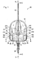
- the Infusion device 10 comprises at least a first Element 12, to which a cannula 13 for insertion into the Body interior of a user (human, animal) (not shown), and a second element 14.
- the second element 14 has a needle 15 which essentially in the longitudinal axis 20 of the second element 14 is arranged.
- the needle 15 is on itself known manner with an axially passing cavity provided, i. in the manner of a known injection needle educated.
- the needle 15 is in the second element 14 with a tube member 17 for the delivery of a therapeutic agent connected, wherein the supply in Fig. 1 by the arrow 11 is indicated.
- the locking element comprises in addition to the jaw member 22 a at substantially rotationally symmetrical and in cross section circular shaped second element 14th formed groove 19, see. in particular FIGS. 2 and 9 and indicated in Fig. 1.
- the groove 19 rotates around the second Element 14 is substantially circular.
- the groove 19 is in the region of the insertion section 23, cf. 6 and 7, formed, i. in the section of the second element 14, which in the locked state in the entry hole 33 of the first element 12 is located.
- the part of the detent element, i. the claw member 22, which is formed in the first element 12 is through a substantially orthogonal to the axis 32 of the entrance hole 33 trained guide 21 out, i. the Guide 21 can only be a simple slot-shaped Be deepening, cf. Fig. 1, in which the jaw element 22 is reciprocally displaceable, cf. Figs. 1 and 2.
- FIGS. 4a, 4b and 5a, 5b show the claw member 22, the the Part of the locking element forms, in the first element 12th is arranged.
- the jaw member 22 is replaced by two separate claw legs 26, 27 formed.
- the claw legs 26, 27 are basically identical, only those with the claw legs 26, 27 respectively connected handle 181, with the claw legs 26, 27 may be formed integrally, in the embodiment shown here with respect to the Illustration of Fig. 1 left version (claw leg 26) and form a right version (claw leg 27).
- the Claw legs 26, 27 have a circular section-shaped Range 263, 273 on. There is a circular section Area 263, 273 provided. The radius 28 this circular section-shaped region 263, 273 corresponds the radius 28, the groove 19 of the second element.
- the circular segment-shaped region 263, 273 is here formed approximately quarter-circular.
- On the claw legs 26, 27 are in the form of an inclined plane formed areas 261, 271 are provided, which are to the free ends 260, 270 taper towards or in relation fall to the inclined plane 261, 271.
- first element 12 cf. Fig. 2, are also provided as inclined plane formed areas 125, 126, namely in there as a guide slot 210th trained guide 21, see Figs. 1, 6 and 7.
- the claw legs 26, 27 are in the guide 21, 210th run parallel to each other and are in this in Direction of the arrow 35 towards each other movable and in opposite direction to the arrow 35 movable, wherein the movement against the direction of the arrows 25 due the elastic counterforce of the claw legs 26, 27 can be done automatically. So it needs for the Movement of the claw legs 26, 27 counter to the direction the arrows 35, the respective handles 181 only to be let go. As a result becomes independent the locking state of the claw legs 26, 27 and of the claw member 22 taken. Good elastic Deformation properties with great durability has, for example, polyacetate POM from which the Claw legs 26, 27 are preferably made.
- the claw legs 26, 27 also have a latching nose 262, 272, compare Figs. 4a, 5a and 2, on. With the Latches 262, 272 they engage behind locking projections 123, 124, in the region of the guide 21 in the first Element are formed, see Fig. 3.
- the locking lugs 262, 272 form together with the latching projections 123, 124 a clip connection which is entered, when the claw legs 26, 27 in the guide 21, 210th introduced during assembly with the first element 12 become.
- the locking lugs 262, 272 form next to one Attachment of the claw legs 26, 27 in the first element 12 also a movement limitation of the claw legs 26, 27 against the direction of the arrows 35, see FIG. Second
- Either the second element 14 is simply in the Entry hole 33 is inserted into it until it is free End 24 to the claw legs 26, 27, see. 2, encounters.
- the free end 24 is designed such that it has a circumferential chamfer 25.
- the bevel 25 is selected to engage the jaw legs 26 slightly grasp the leg inner sides 263, 273 can and in the course of movement of the second element 14 in the entry hole 33 in, the legs 26, 27 in Direction of the arrows 34 moves away from each other, as the Bevel 27 for the claw legs 26, 27 in this Trap forms an inclined plane. If you move on the front cylindrical part of the second element 14 when the second element 14 its constructive certain end position in the entry hole 33 of first element reaches 12, also the claw legs 26, 27 with the groove 19 curse, so that the claw legs 26, 27 latch into the groove 19 latch.
- the claw legs 26, 27 may slightly from the protrude first element 12 forming body, see. Fig. 1.
- a handle 180 is provided, wherein the handle 180, here in the form of a broadening of the Claw legs 26, 27 is formed in the first element 12 in the form of a likewise trained there leadership 210 can be performed.
- the handle 181 points at her Actuation side handle improving means 183, for example in the form of grooves or depressions, or it is there provided a non-slip element.
- the side 122 of the first element 12, cf. Fig. 2, the is to lie on the skin of a user is essentially flat and can also be ergonomic be shaped so that they are in the relevant Applizierungs Kunststoff the infusion device 10 am Body of the user can nestle, without negative Sensations on the part of the user during wearing cause the infusion device 10.
- the second element 14 has at its free end 24th a substantially axial recess 272, in the the needle 15 with its tip portion 150 in it.
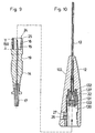
- the protruding into the recess 172 tip area 150 is sized so that the needle 15 with her immediate tip does not have the free end 24 stands out, cf. 9 it can be seen from FIG. that the opening portion 130 of the cannula 13, the free end 24 of the second element 14 is directed, into the entry hole 33 in such a way that in locked state of the first and second elements 12, 13, the needle 15 in a front of the entrance hole 33 in the there widening opening of the cannula 13th arranged closure element 131 can penetrate. The Tip of the needle 15 then comes in the widened opening area the cannula 13, cf.
- Closure element 131 the guide means 133, see. Fig. 10, at its intended location before in Direction of the entrance hole 33 widening Opening portion 130 is seated, may be made of elastomeric and / or be formed polymeric material, for example Rubber or another suitable human or veterinary medicine harmless material.
- the cannula 13 is at its in the first element 12 to are coming cannula end 134, see Fig. 8, with surrounded a sleeve member 135.
- the closure element 131 is arranged and in the direction the exit-side end of the therapeutic agent 11 from the Cannula, i. in front of the closure element 131, is a Connecting element 137 is arranged, via which the cannula 13 is connected to the sleeve member 135.
- the cannula 13 and the sleeve member 135 and the recorded therein Closure element 131 and the connecting element 137 form a mounting unit, which in the first element 12 in the trained there in the bag-trained Opening 127 can be used.
- the opening 127 is preferably a press fit for the sleeve member 135 formed so that no further stop or Safety measures between the first element 12 and the sleeve member 135 must be provided.
- an obtuse angle in the range of 183 ° may be formed be so that the cannula 13 relative to the body of the first element 12 is inclined.
- second element 140 is different from the second element shown in the other figures 14 in that the second element 140 a very much longer needle 151 than the needle 15 has.
- the second Element 140 according to FIG. 7 is not with a hose element 17 for the supply of a therapeutic agent 11 connected, but there is the needle 151 to appropriate Way in the front region of the second element 140, i. the area with which the second element 140 on otherwise same way as described above, connected and becomes the same with the first element 12 connected like the second element 14.
- the needle 151 is so long that this in their top area 150th locked state of the first and second members 12, 140 from the normally to the outlet of the administered Therapeutics 11 specific tip of the cannula slightly protruding, see Fig. 7.
- the Needle 151 can easily enter the body in a known manner of the person or animal to be treated introduced during the introduction of the Needle 151 also the cannula 13 slightly into the body can be introduced.
- the second element 141 from the first Element 12 pulled out and instead of the second Elements 140, the second element 14 used, namely such as in the end position shown in Fig. 6 is shown. It pierces the with a cavity provided needle 15, the closure member 131, so that via the hose member 17 through the needle 15 supplied Therapeutic 11 into the cannula 13 and from there into the body of the person to be treated or Animal can get.
- the in conjunction with the modified second element 140 used insertion needle 151 may be void-free, but it can also with the type of injection needle be provided an axially continuous cavity.
- the long insertion needle 151 with a continuous Cavity is provided in this one of the outer of the Needle from opening into the cavity 136 be provided, see Fig. 7.
- the opening 136 is provided such that in the merged state of first and second elements 12, 140 in the area the element-side opening 12 of the cannula 13 is provided is, i. in the embodiment of the infusion device 10 as shown in FIG. 7, the opening 136 opens into the to second element 140 widening opening or the Cavity in the connecting element 137, in the sleeve element 135 is arranged.
- This embodiment of the insertion needle 151 with continuous cavity and opening 136 is then provided when the infusion device 10 in the course of Sterilization not with ionizing radiation, for example ⁇ -rays, is sterilized but with an optionally oxidizing gas.
- the gas can then from the Tip portion 150 of the insertion needle 151 through the Cavity of the insertion needle 151 into the area of element-side 12 cannula opening 132 pass and from there from over the opening 136 in the funnel-shaped expanding interior of the connecting element 137th
- the gas between the forcibly formed annular Interior between the insertion needle 151 and the cannula 13 again to the outlet end of the cannula 13th be guided and possibly from there back into the cycle of the sterilizing gas.
Landscapes
- Health & Medical Sciences (AREA)
- Vascular Medicine (AREA)
- Engineering & Computer Science (AREA)
- Anesthesiology (AREA)
- Biomedical Technology (AREA)
- Heart & Thoracic Surgery (AREA)
- Hematology (AREA)
- Life Sciences & Earth Sciences (AREA)
- Animal Behavior & Ethology (AREA)
- General Health & Medical Sciences (AREA)
- Public Health (AREA)
- Veterinary Medicine (AREA)
- Infusion, Injection, And Reservoir Apparatuses (AREA)
Priority Applications (7)
| Application Number | Priority Date | Filing Date | Title |
|---|---|---|---|
| ES01111331T ES2230200T3 (es) | 2001-05-09 | 2001-05-09 | Dispositivo para la administracion de un agente terapeutico. |
| AT01111331T ATE277667T1 (de) | 2001-05-09 | 2001-05-09 | Infusionseinrichtung für die verabreichung eines therapeutikums |
| EP01111331A EP1256358B1 (de) | 2001-05-09 | 2001-05-09 | Infusionseinrichtung für die Verabreichung eines Therapeutikums |
| DE50103873T DE50103873D1 (de) | 2001-05-09 | 2001-05-09 | Infusionseinrichtung für die Verabreichung eines Therapeutikums |
| DK01111331T DK1256358T3 (da) | 2001-05-09 | 2001-05-09 | Infusionsindretning til indgift af et terapeutikum |
| CA002350067A CA2350067C (en) | 2001-05-09 | 2001-06-07 | Infusion apparatus for administering a medicine |
| US09/875,273 US6488663B1 (en) | 2001-05-09 | 2001-06-07 | Infusion apparatus for administering a medicine |
Applications Claiming Priority (1)
| Application Number | Priority Date | Filing Date | Title |
|---|---|---|---|
| EP01111331A EP1256358B1 (de) | 2001-05-09 | 2001-05-09 | Infusionseinrichtung für die Verabreichung eines Therapeutikums |
Publications (2)
| Publication Number | Publication Date |
|---|---|
| EP1256358A1 EP1256358A1 (de) | 2002-11-13 |
| EP1256358B1 true EP1256358B1 (de) | 2004-09-29 |
Family
ID=8177371
Family Applications (1)
| Application Number | Title | Priority Date | Filing Date |
|---|---|---|---|
| EP01111331A Expired - Lifetime EP1256358B1 (de) | 2001-05-09 | 2001-05-09 | Infusionseinrichtung für die Verabreichung eines Therapeutikums |
Country Status (7)
| Country | Link |
|---|---|
| US (1) | US6488663B1 (da) |
| EP (1) | EP1256358B1 (da) |
| AT (1) | ATE277667T1 (da) |
| CA (1) | CA2350067C (da) |
| DE (1) | DE50103873D1 (da) |
| DK (1) | DK1256358T3 (da) |
| ES (1) | ES2230200T3 (da) |
Families Citing this family (86)
| Publication number | Priority date | Publication date | Assignee | Title |
|---|---|---|---|---|
| US5954643A (en) * | 1997-06-09 | 1999-09-21 | Minimid Inc. | Insertion set for a transcutaneous sensor |
| USD526409S1 (en) | 1998-07-14 | 2006-08-08 | Unomedical A/S | Medical puncturing device |
| WO2002032287A2 (en) * | 2000-10-17 | 2002-04-25 | Schneider Patricia G | Emergency medical dispensing card |
| WO2002070037A2 (en) | 2001-03-04 | 2002-09-12 | Sterling Medivations, Inc. | Infusion hub assembly and fluid line disconnect system |
| EP1815879A3 (en) * | 2001-05-18 | 2007-11-14 | Deka Products Limited Partnership | Infusion set for a fluid pump |
| US8034026B2 (en) | 2001-05-18 | 2011-10-11 | Deka Products Limited Partnership | Infusion pump assembly |
| US6830562B2 (en) | 2001-09-27 | 2004-12-14 | Unomedical A/S | Injector device for placing a subcutaneous infusion set |
| ITTO20011228A1 (it) | 2001-12-28 | 2003-06-28 | Cane Srl | Contenitore per ago monouso. |
| AU2003208296A1 (en) | 2002-02-12 | 2003-09-04 | Unomedial A/S | Infusion device with needle shield |
| US7338465B2 (en) | 2002-07-02 | 2008-03-04 | Patton Medical Devices, Lp | Infusion device and method thereof |
| DK1556124T3 (da) | 2002-09-02 | 2008-02-18 | Unomedical As | Apparatur og fremgangsmåde til justering af en infusionsslanges længde |
| US20040051019A1 (en) | 2002-09-02 | 2004-03-18 | Mogensen Lasse Wesseltoft | Apparatus for and a method of adjusting the length of an infusion tube |
| US7115112B2 (en) | 2002-09-02 | 2006-10-03 | Unomedical A/S | Device for subcutaneous administration of a medicament to a patient and tubing for same |
| US7258680B2 (en) | 2002-09-02 | 2007-08-21 | Unomedical A/S | Device for subcutaneous administration of a medicament to a patient |
| DK200201823A (da) | 2002-11-26 | 2004-05-27 | Maersk Medical As | Forbindelsesstykke for en slangeforbindelse |
| US20040158202A1 (en) | 2003-02-12 | 2004-08-12 | Soren Jensen | Cover |
| US7070580B2 (en) | 2003-04-01 | 2006-07-04 | Unomedical A/S | Infusion device and an adhesive sheet material and a release liner |
| JP2004305466A (ja) * | 2003-04-08 | 2004-11-04 | Nipro Corp | 医療用コネクターセット及びそれを用いた留置用カテーテルセット |
| JP3864925B2 (ja) * | 2003-04-08 | 2007-01-10 | ニプロ株式会社 | 留置用カテーテルセット |
| US6926694B2 (en) * | 2003-05-09 | 2005-08-09 | Medsolve Technologies, Llc | Apparatus and method for delivery of therapeutic and/or diagnostic agents |
| USD554253S1 (en) | 2003-10-15 | 2007-10-30 | Unomedical A/S | Medical infusion device |
| USD576267S1 (en) | 2003-10-15 | 2008-09-02 | Unomedical A/S | Medical infusion device |
| USD579541S1 (en) | 2003-10-15 | 2008-10-28 | Unomedical A/S | Medical insertion device |
| US8029454B2 (en) | 2003-11-05 | 2011-10-04 | Baxter International Inc. | High convection home hemodialysis/hemofiltration and sorbent system |
| US7309326B2 (en) * | 2003-11-18 | 2007-12-18 | Icu Medical, Inc. | Infusion set |
| ATE424228T1 (de) | 2004-03-26 | 2009-03-15 | Unomedical As | Infusionsset |
| US8062250B2 (en) | 2004-08-10 | 2011-11-22 | Unomedical A/S | Cannula device |
| US7850650B2 (en) | 2005-07-11 | 2010-12-14 | Covidien Ag | Needle safety shield with reset |
| US7905857B2 (en) | 2005-07-11 | 2011-03-15 | Covidien Ag | Needle assembly including obturator with safety reset |
| US7828773B2 (en) | 2005-07-11 | 2010-11-09 | Covidien Ag | Safety reset key and needle assembly |
| US7303543B1 (en) | 2004-12-03 | 2007-12-04 | Medtronic Minimed, Inc. | Medication infusion set |
| US7867199B2 (en) | 2004-12-10 | 2011-01-11 | Unomedical A/S | Inserter |
| US7704229B2 (en) | 2005-02-03 | 2010-04-27 | Medtronic Minimed, Inc. | Insertion device |
| US7985199B2 (en) | 2005-03-17 | 2011-07-26 | Unomedical A/S | Gateway system |
| US20060276747A1 (en) | 2005-06-06 | 2006-12-07 | Sherwood Services Ag | Needle assembly with removable depth stop |
| MX2007016062A (es) | 2005-06-28 | 2008-03-10 | Unomedical As | Empaquetamiento para juego de infusion y metodo para aplicar un juego de infusion. |
| US7731692B2 (en) | 2005-07-11 | 2010-06-08 | Covidien Ag | Device for shielding a sharp tip of a cannula and method of using the same |
| US8551047B2 (en) | 2005-08-22 | 2013-10-08 | Patton Medical Devices, Lp | Fluid delivery devices, systems and methods |
| ATE480278T1 (de) | 2005-09-12 | 2010-09-15 | Unomedical As | Einfürungssystem für ein infusionsset mit einem ersten und zweiten federeinheit |
| US7654735B2 (en) | 2005-11-03 | 2010-02-02 | Covidien Ag | Electronic thermometer |
| US8226614B2 (en) | 2005-11-03 | 2012-07-24 | Patton Medical Devices, Lp | Fluid delivery devices, systems and methods |
| USD655807S1 (en) | 2005-12-09 | 2012-03-13 | Unomedical A/S | Medical device |
| DE602006006477D1 (de) | 2005-12-23 | 2009-06-04 | Unomedical As | Verabreichungsgerät |
| US7892216B2 (en) | 2006-02-07 | 2011-02-22 | Icu Medical, Inc. | Infusion set |
| RU2309668C1 (ru) | 2006-02-20 | 2007-11-10 | Александр Сергеевич Парфенов | Способ неинвазивного определения функции эндотелия и устройство для его осуществления |
| AU2007219546B8 (en) | 2006-02-28 | 2012-07-05 | Unomedical A/S | Inserter for infusion part and infusion part provided with needle protector |
| WO2007140783A2 (en) | 2006-06-07 | 2007-12-13 | Unomedical A/S | Inserter for transcutaneous sensor |
| KR20090028701A (ko) | 2006-06-09 | 2009-03-19 | 우노메디컬 에이/에스 | 장착 패드 |
| CA2659077A1 (en) * | 2006-08-02 | 2008-02-07 | Unomedical A/S | Insertion device |
| RU2443436C2 (ru) | 2006-08-02 | 2012-02-27 | Уномедикал А/С | Канюльное и доставочное устройство |
| JP4994775B2 (ja) | 2006-10-12 | 2012-08-08 | 日本コヴィディエン株式会社 | 針先保護具 |
| EP1917990A1 (en) | 2006-10-31 | 2008-05-07 | Unomedical A/S | Infusion set |
| EP2155311B1 (en) | 2007-06-20 | 2013-01-02 | Unomedical A/S | A method and an apparatus for making a catheter |
| EP2185224A1 (en) | 2007-07-03 | 2010-05-19 | Unomedical A/S | Inserter having bistable equilibrium states |
| GB2445437B (en) * | 2007-07-06 | 2008-11-26 | Applied Medical Technology Ltd | Cannula insertion device |
| RU2010104457A (ru) | 2007-07-10 | 2011-08-20 | Уномедикал А/С (Dk) | Устройство ввода с двумя пружинами |
| NZ582226A (en) | 2007-07-18 | 2011-12-22 | Unomedical As | Insertion device with a pivoting action from a first to a second position and longitudinal action to a third position in the direction of insertion. |
| WO2009045622A1 (en) * | 2007-08-10 | 2009-04-09 | Medi-Life Cards, Llc | Method and apparatus for auto injection of a therapeutic |
| US8357104B2 (en) | 2007-11-01 | 2013-01-22 | Coviden Lp | Active stylet safety shield |
| RU2010137844A (ru) | 2008-02-13 | 2012-03-20 | Уномедикал А/С (Dk) | Уплотнение между канюльной частью и путем прохождения текучей среды |
| CA2715667A1 (en) | 2008-02-20 | 2009-08-27 | Unomedical A/S | Insertion device with horizontally moving part |
| US8016789B2 (en) | 2008-10-10 | 2011-09-13 | Deka Products Limited Partnership | Pump assembly with a removable cover assembly |
| US9180245B2 (en) | 2008-10-10 | 2015-11-10 | Deka Products Limited Partnership | System and method for administering an infusible fluid |
| US8262616B2 (en) | 2008-10-10 | 2012-09-11 | Deka Products Limited Partnership | Infusion pump assembly |
| US8223028B2 (en) | 2008-10-10 | 2012-07-17 | Deka Products Limited Partnership | Occlusion detection system and method |
| US8066672B2 (en) | 2008-10-10 | 2011-11-29 | Deka Products Limited Partnership | Infusion pump assembly with a backup power supply |
| US8267892B2 (en) | 2008-10-10 | 2012-09-18 | Deka Products Limited Partnership | Multi-language / multi-processor infusion pump assembly |
| US8708376B2 (en) | 2008-10-10 | 2014-04-29 | Deka Products Limited Partnership | Medium connector |
| CN102256657A (zh) | 2008-12-22 | 2011-11-23 | 犹诺医药有限公司 | 包括粘合垫的医疗器械 |
| US8057400B2 (en) | 2009-05-12 | 2011-11-15 | Angiologix, Inc. | System and method of measuring changes in arterial volume of a limb segment |
| JP2013500099A (ja) | 2009-07-30 | 2013-01-07 | ウノメディカル・アー/エス | 水平方向の可動部材を備えた挿入デバイス |
| CN102548598B (zh) | 2009-08-07 | 2014-09-17 | 犹诺医药有限公司 | 具有传感器和一个或多个插管的传送装置 |
| CA2792138A1 (en) | 2010-03-30 | 2011-10-06 | Unomedical A/S | Medical device |
| EP2433663A1 (en) | 2010-09-27 | 2012-03-28 | Unomedical A/S | Insertion system |
| EP2436412A1 (en) | 2010-10-04 | 2012-04-04 | Unomedical A/S | A sprinkler cannula |
| US8486024B2 (en) | 2011-04-27 | 2013-07-16 | Covidien Lp | Safety IV catheter assemblies |
| EP2760520A1 (en) | 2011-09-26 | 2014-08-06 | Covidien LP | Safety catheter |
| WO2013048768A1 (en) | 2011-09-26 | 2013-04-04 | Covidien Lp | Safety iv catheter and needle assembly |
| EP2763723B1 (en) | 2011-10-05 | 2016-04-13 | Unomedical A/S | Inserter for simultaneous insertion of multiple transcutaneous parts |
| EP2766074B1 (en) | 2011-10-14 | 2020-04-08 | Kpr U.S., Llc | Safety iv catheter assembly |
| EP2583715A1 (en) | 2011-10-19 | 2013-04-24 | Unomedical A/S | Infusion tube system and method for manufacture |
| US9440051B2 (en) | 2011-10-27 | 2016-09-13 | Unomedical A/S | Inserter for a multiplicity of subcutaneous parts |
| US10413658B2 (en) | 2017-03-31 | 2019-09-17 | Capillary Biomedical, Inc. | Helical insertion infusion device |
| WO2020097552A1 (en) | 2018-11-08 | 2020-05-14 | Capillary Biomedical, Inc | Linear insertion device with rotational drive |
| US12214159B2 (en) | 2020-08-28 | 2025-02-04 | Tandem Diabetes Care, Inc | Insulin infusion set |
| CN118454018B (zh) * | 2024-07-10 | 2024-09-06 | 中国人民解放军西部战区总医院 | 一种肿瘤内科给药装置 |
Family Cites Families (8)
| Publication number | Priority date | Publication date | Assignee | Title |
|---|---|---|---|---|
| US5514117A (en) * | 1988-09-06 | 1996-05-07 | Lynn; Lawrence A. | Connector having a medical cannula |
| US5603706A (en) * | 1992-09-29 | 1997-02-18 | Wyatt; Philip | Infusion apparatus |
| DK25793A (da) * | 1993-03-09 | 1994-09-10 | Pharma Plast Int As | Infusionssæt til intermitterende eller kontinuerlig indgivelse af et terapeutisk middel |
| US5423775A (en) * | 1994-01-21 | 1995-06-13 | Winfield Industries | Locking connector assembly |
| US5728071A (en) * | 1996-09-09 | 1998-03-17 | Watson; Robert L. | Injection patch |
| US6056718A (en) * | 1998-03-04 | 2000-05-02 | Minimed Inc. | Medication infusion set |
| US6086575A (en) * | 1998-03-20 | 2000-07-11 | Maersk Medical A/S | Subcutaneous infusion device |
| US6123690A (en) * | 1998-03-20 | 2000-09-26 | Maersk Medical A/S | Subcutaneous infusion device |
-
2001
- 2001-05-09 DE DE50103873T patent/DE50103873D1/de not_active Expired - Lifetime
- 2001-05-09 AT AT01111331T patent/ATE277667T1/de not_active IP Right Cessation
- 2001-05-09 ES ES01111331T patent/ES2230200T3/es not_active Expired - Lifetime
- 2001-05-09 DK DK01111331T patent/DK1256358T3/da active
- 2001-05-09 EP EP01111331A patent/EP1256358B1/de not_active Expired - Lifetime
- 2001-06-07 CA CA002350067A patent/CA2350067C/en not_active Expired - Fee Related
- 2001-06-07 US US09/875,273 patent/US6488663B1/en not_active Expired - Lifetime
Also Published As
| Publication number | Publication date |
|---|---|
| DK1256358T3 (da) | 2005-01-10 |
| CA2350067C (en) | 2009-04-07 |
| US6488663B1 (en) | 2002-12-03 |
| US20020169419A1 (en) | 2002-11-14 |
| ES2230200T3 (es) | 2005-05-01 |
| DE50103873D1 (de) | 2004-11-04 |
| ATE277667T1 (de) | 2004-10-15 |
| EP1256358A1 (de) | 2002-11-13 |
| CA2350067A1 (en) | 2002-11-09 |
Similar Documents
| Publication | Publication Date | Title |
|---|---|---|
| EP1256358B1 (de) | Infusionseinrichtung für die Verabreichung eines Therapeutikums | |
| DE69114362T2 (de) | Nadelanordnung. | |
| DE10254443B4 (de) | Einsetzhilfe zum Einsetzen eines Katheterkopfes in ein organisches Gewebe | |
| DE69619738T2 (de) | Nadelanordnung für Subkutaninjektionen | |
| DE69812542T2 (de) | Sicherheitseinwegspritze | |
| DE69704513T2 (de) | Baueinheit aus Spritze und Nadelschutz | |
| DE69322144T2 (de) | Sichere Einwegspritze mit zurückziehbarer selbstvorgespannter Nadel | |
| DE69320889T2 (de) | Sicherheitsspritze zum Anschliessen an eine intravenöse Zugangsöffnung | |
| DE69330374T2 (de) | Injektor und dessen anwendung | |
| DE102006041809B4 (de) | Nadelschutzvorrichtung mit Blockiereinrichtung | |
| DE69009131T2 (de) | Vorgeschlitzte injektionsvorrichtung sowie konische kanüle. | |
| DE69320862T2 (de) | Injektionsspritze mit geschützter Nadel | |
| DE102006042233B3 (de) | Nadelschutzvorrichtung mit distalem und proximalem Nadelschutz | |
| DE69918242T2 (de) | Sicherheitsspritze | |
| DE69008850T2 (de) | Spritze mit auswechselbarer und zurückziehbarer kanülenplattform. | |
| DE60210735T2 (de) | Transfervorrichtung sowie System mit einer Kappenanordnung, einem Behälter und der Transfervorrichtung | |
| DE69827328T2 (de) | Vormontierte Spritze | |
| DE69926675T2 (de) | Schnittstelle zwischen einem Phiolebehälter und einer stiftförmigen Medikamentenspritze | |
| DE69918493T2 (de) | Schutzhülse für vorgefüllte Spritzen | |
| DE69429000T2 (de) | Einwegspritze mit automatischer nadelabdeckung | |
| DE69624983T2 (de) | Spitzen-Schutzvorrichtung | |
| DE69421928T2 (de) | Dosierspritze | |
| DE69319651T2 (de) | Intravenöser Katheter mit Nadelschutzvorrichtung | |
| DE602004013125T2 (de) | Sicherheits-nadelschutz für spritzen | |
| WO2007031125A1 (de) | Insertionskopf mit nadelschutz im griff |
Legal Events
| Date | Code | Title | Description |
|---|---|---|---|
| PUAI | Public reference made under article 153(3) epc to a published international application that has entered the european phase |
Free format text: ORIGINAL CODE: 0009012 |
|
| AK | Designated contracting states |
Kind code of ref document: A1 Designated state(s): AT BE CH CY DE DK ES FI FR GB GR IE IT LI LU MC NL PT SE TR |
|
| AX | Request for extension of the european patent |
Free format text: AL PAYMENT 20010531;LT PAYMENT 20010531;LV PAYMENT 20010531;MK PAYMENT 20010531;RO PAYMENT 20010531;SI PAYMENT 20010531 |
|
| AKX | Designation fees paid |
Designated state(s): AT BE CH CY DE DK ES FI FR GB GR IE IT LI LU MC NL PT SE TR |
|
| AXX | Extension fees paid |
Extension state: LT Payment date: 20010531 Extension state: AL Payment date: 20010531 Extension state: RO Payment date: 20010531 Extension state: SI Payment date: 20010531 Extension state: MK Payment date: 20010531 Extension state: LV Payment date: 20010531 |
|
| 17P | Request for examination filed |
Effective date: 20030730 |
|
| GRAP | Despatch of communication of intention to grant a patent |
Free format text: ORIGINAL CODE: EPIDOSNIGR1 |
|
| GRAS | Grant fee paid |
Free format text: ORIGINAL CODE: EPIDOSNIGR3 |
|
| GRAA | (expected) grant |
Free format text: ORIGINAL CODE: 0009210 |
|
| AK | Designated contracting states |
Kind code of ref document: B1 Designated state(s): AT BE CH CY DE DK ES FI FR GB GR IE IT LI LU MC NL PT SE TR |
|
| AX | Request for extension of the european patent |
Extension state: AL LT LV MK RO SI |
|
| PG25 | Lapsed in a contracting state [announced via postgrant information from national office to epo] |
Ref country code: IE Free format text: LAPSE BECAUSE OF FAILURE TO SUBMIT A TRANSLATION OF THE DESCRIPTION OR TO PAY THE FEE WITHIN THE PRESCRIBED TIME-LIMIT Effective date: 20040929 Ref country code: FI Free format text: LAPSE BECAUSE OF FAILURE TO SUBMIT A TRANSLATION OF THE DESCRIPTION OR TO PAY THE FEE WITHIN THE PRESCRIBED TIME-LIMIT Effective date: 20040929 |
|
| REG | Reference to a national code |
Ref country code: GB Ref legal event code: FG4D Free format text: NOT ENGLISH |
|
| REG | Reference to a national code |
Ref country code: CH Ref legal event code: EP |
|
| REG | Reference to a national code |
Ref country code: IE Ref legal event code: FG4D Free format text: GERMAN |
|
| REF | Corresponds to: |
Ref document number: 50103873 Country of ref document: DE Date of ref document: 20041104 Kind code of ref document: P |
|
| PG25 | Lapsed in a contracting state [announced via postgrant information from national office to epo] |
Ref country code: GR Free format text: LAPSE BECAUSE OF FAILURE TO SUBMIT A TRANSLATION OF THE DESCRIPTION OR TO PAY THE FEE WITHIN THE PRESCRIBED TIME-LIMIT Effective date: 20041229 |
|
| REG | Reference to a national code |
Ref country code: SE Ref legal event code: TRGR |
|
| REG | Reference to a national code |
Ref country code: CH Ref legal event code: NV Representative=s name: ISLER & PEDRAZZINI AG Ref country code: CH Ref legal event code: PUE Owner name: UNOMEDICAL A/S Free format text: ARTA PLAST AB#ANTENNVAEGEN 1A#135 48 TYRESOE (SE) -TRANSFER TO- UNOMEDICAL A/S#ENGMOSEN 1#3540 LYNGE (DK) |
|
| RAP2 | Party data changed (patent owner data changed or rights of a patent transferred) |
Owner name: UNOMEDICAL A/S |
|
| NLT2 | Nl: modifications (of names), taken from the european patent patent bulletin |
Owner name: UNOMEDICAL A/S |
|
| GBT | Gb: translation of ep patent filed (gb section 77(6)(a)/1977) |
Effective date: 20050210 |
|
| LTIE | Lt: invalidation of european patent or patent extension |
Effective date: 20040929 |
|
| REG | Reference to a national code |
Ref country code: IE Ref legal event code: FD4D |
|
| REG | Reference to a national code |
Ref country code: GB Ref legal event code: 732E |
|
| REG | Reference to a national code |
Ref country code: ES Ref legal event code: FG2A Ref document number: 2230200 Country of ref document: ES Kind code of ref document: T3 |
|
| PG25 | Lapsed in a contracting state [announced via postgrant information from national office to epo] |
Ref country code: LU Free format text: LAPSE BECAUSE OF NON-PAYMENT OF DUE FEES Effective date: 20050509 Ref country code: CY Free format text: LAPSE BECAUSE OF FAILURE TO SUBMIT A TRANSLATION OF THE DESCRIPTION OR TO PAY THE FEE WITHIN THE PRESCRIBED TIME-LIMIT Effective date: 20050509 Ref country code: AT Free format text: LAPSE BECAUSE OF NON-PAYMENT OF DUE FEES Effective date: 20050509 |
|
| PG25 | Lapsed in a contracting state [announced via postgrant information from national office to epo] |
Ref country code: MC Free format text: LAPSE BECAUSE OF NON-PAYMENT OF DUE FEES Effective date: 20050531 Ref country code: BE Free format text: LAPSE BECAUSE OF NON-PAYMENT OF DUE FEES Effective date: 20050531 |
|
| NLS | Nl: assignments of ep-patents |
Owner name: UNOMEDICAL A/S |
|
| PLBE | No opposition filed within time limit |
Free format text: ORIGINAL CODE: 0009261 |
|
| STAA | Information on the status of an ep patent application or granted ep patent |
Free format text: STATUS: NO OPPOSITION FILED WITHIN TIME LIMIT |
|
| ET | Fr: translation filed | ||
| 26N | No opposition filed |
Effective date: 20050630 |
|
| BERE | Be: lapsed |
Owner name: *ARTA PLAST A.B. Effective date: 20050531 |
|
| REG | Reference to a national code |
Ref country code: CH Ref legal event code: PCAR Free format text: ISLER & PEDRAZZINI AG;POSTFACH 1772;8027 ZUERICH (CH) |
|
| BERE | Be: lapsed |
Owner name: *ARTA PLAST A.B. Effective date: 20050531 |
|
| PG25 | Lapsed in a contracting state [announced via postgrant information from national office to epo] |
Ref country code: PT Free format text: LAPSE BECAUSE OF NON-PAYMENT OF DUE FEES Effective date: 20050228 |
|
| PGFP | Annual fee paid to national office [announced via postgrant information from national office to epo] |
Ref country code: TR Payment date: 20120413 Year of fee payment: 12 Ref country code: CH Payment date: 20120514 Year of fee payment: 12 Ref country code: NL Payment date: 20120515 Year of fee payment: 12 Ref country code: DK Payment date: 20120510 Year of fee payment: 12 |
|
| PGFP | Annual fee paid to national office [announced via postgrant information from national office to epo] |
Ref country code: SE Payment date: 20120511 Year of fee payment: 12 |
|
| PGFP | Annual fee paid to national office [announced via postgrant information from national office to epo] |
Ref country code: IT Payment date: 20120421 Year of fee payment: 12 |
|
| PGFP | Annual fee paid to national office [announced via postgrant information from national office to epo] |
Ref country code: ES Payment date: 20120607 Year of fee payment: 12 |
|
| REG | Reference to a national code |
Ref country code: NL Ref legal event code: V1 Effective date: 20131201 |
|
| REG | Reference to a national code |
Ref country code: CH Ref legal event code: PL |
|
| REG | Reference to a national code |
Ref country code: SE Ref legal event code: EUG |
|
| PG25 | Lapsed in a contracting state [announced via postgrant information from national office to epo] |
Ref country code: SE Free format text: LAPSE BECAUSE OF NON-PAYMENT OF DUE FEES Effective date: 20130510 Ref country code: LI Free format text: LAPSE BECAUSE OF NON-PAYMENT OF DUE FEES Effective date: 20130531 Ref country code: CH Free format text: LAPSE BECAUSE OF NON-PAYMENT OF DUE FEES Effective date: 20130531 |
|
| REG | Reference to a national code |
Ref country code: DK Ref legal event code: EBP Effective date: 20130531 |
|
| PG25 | Lapsed in a contracting state [announced via postgrant information from national office to epo] |
Ref country code: NL Free format text: LAPSE BECAUSE OF NON-PAYMENT OF DUE FEES Effective date: 20131201 Ref country code: IT Free format text: LAPSE BECAUSE OF NON-PAYMENT OF DUE FEES Effective date: 20130509 |
|
| PG25 | Lapsed in a contracting state [announced via postgrant information from national office to epo] |
Ref country code: DK Free format text: LAPSE BECAUSE OF NON-PAYMENT OF DUE FEES Effective date: 20130531 |
|
| REG | Reference to a national code |
Ref country code: ES Ref legal event code: FD2A Effective date: 20140911 |
|
| PG25 | Lapsed in a contracting state [announced via postgrant information from national office to epo] |
Ref country code: ES Free format text: LAPSE BECAUSE OF NON-PAYMENT OF DUE FEES Effective date: 20130510 |
|
| PG25 | Lapsed in a contracting state [announced via postgrant information from national office to epo] |
Ref country code: TR Free format text: LAPSE BECAUSE OF NON-PAYMENT OF DUE FEES Effective date: 20130509 |
|
| REG | Reference to a national code |
Ref country code: FR Ref legal event code: PLFP Year of fee payment: 16 |
|
| REG | Reference to a national code |
Ref country code: FR Ref legal event code: PLFP Year of fee payment: 17 |
|
| REG | Reference to a national code |
Ref country code: FR Ref legal event code: PLFP Year of fee payment: 18 |
|
| PGFP | Annual fee paid to national office [announced via postgrant information from national office to epo] |
Ref country code: FR Payment date: 20200414 Year of fee payment: 20 Ref country code: DE Payment date: 20200428 Year of fee payment: 20 |
|
| PGFP | Annual fee paid to national office [announced via postgrant information from national office to epo] |
Ref country code: GB Payment date: 20200429 Year of fee payment: 20 |
|
| REG | Reference to a national code |
Ref country code: DE Ref legal event code: R071 Ref document number: 50103873 Country of ref document: DE |
|
| REG | Reference to a national code |
Ref country code: GB Ref legal event code: PE20 Expiry date: 20210508 |
|
| PG25 | Lapsed in a contracting state [announced via postgrant information from national office to epo] |
Ref country code: GB Free format text: LAPSE BECAUSE OF EXPIRATION OF PROTECTION Effective date: 20210508 |