EP1256945A2 - Prisme à réflexion avec plusieurs surfaces latérales et tête de lecture optique - Google Patents
Prisme à réflexion avec plusieurs surfaces latérales et tête de lecture optique Download PDFInfo
- Publication number
- EP1256945A2 EP1256945A2 EP02253263A EP02253263A EP1256945A2 EP 1256945 A2 EP1256945 A2 EP 1256945A2 EP 02253263 A EP02253263 A EP 02253263A EP 02253263 A EP02253263 A EP 02253263A EP 1256945 A2 EP1256945 A2 EP 1256945A2
- Authority
- EP
- European Patent Office
- Prior art keywords
- light beam
- light
- reflection
- face
- optical pickup
- Prior art date
- Legal status (The legal status is an assumption and is not a legal conclusion. Google has not performed a legal analysis and makes no representation as to the accuracy of the status listed.)
- Granted
Links
Images




Classifications
-
- G—PHYSICS
- G11—INFORMATION STORAGE
- G11B—INFORMATION STORAGE BASED ON RELATIVE MOVEMENT BETWEEN RECORD CARRIER AND TRANSDUCER
- G11B7/00—Recording or reproducing by optical means, e.g. recording using a thermal beam of optical radiation by modifying optical properties or the physical structure, reproducing using an optical beam at lower power by sensing optical properties; Record carriers therefor
- G11B7/12—Heads, e.g. forming of the optical beam spot or modulation of the optical beam
- G11B7/135—Means for guiding the beam from the source to the record carrier or from the record carrier to the detector
- G11B7/1359—Single prisms
-
- G—PHYSICS
- G02—OPTICS
- G02B—OPTICAL ELEMENTS, SYSTEMS OR APPARATUS
- G02B5/00—Optical elements other than lenses
- G02B5/04—Prisms
-
- G—PHYSICS
- G11—INFORMATION STORAGE
- G11B—INFORMATION STORAGE BASED ON RELATIVE MOVEMENT BETWEEN RECORD CARRIER AND TRANSDUCER
- G11B7/00—Recording or reproducing by optical means, e.g. recording using a thermal beam of optical radiation by modifying optical properties or the physical structure, reproducing using an optical beam at lower power by sensing optical properties; Record carriers therefor
- G11B2007/0003—Recording, reproducing or erasing systems characterised by the structure or type of the carrier
- G11B2007/0006—Recording, reproducing or erasing systems characterised by the structure or type of the carrier adapted for scanning different types of carrier, e.g. CD & DVD
Definitions
- the present invention relates to a many-sided reflection prism which reduces a height of an optical system, and to a slim compatible optical pickup.
- an optical pickup depends upon the effective diameter of an objective lens, i.e., the diameter of an incident light beam, the thickness of the objective lens, and the working distance of the objective lens. Therefore, to implement a compact, slim, light-weight optical pickup, there is a need to reduce the size of an objective lens and other optical elements.
- an optical pickup for use in optical recording/reproduction apparatuses for example, DVD/CD compatible optical disc drives, which are employed to provide portable personal computers with multiple and complex functions, needs to be slimmed down.
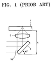
- a conventional optical pickup has an optical structure constructed such that a light beam traveling horizontally from a light source (not shown) is reflected in a height direction by a reflection mirror 5 having a sloping reflection face 5a of 45° and then focused onto an optical disc 1 by an objective lens 3.
- Recording densities are determined by the size of a light spot focused onto the recording surface of the optical disc 10 by the objective lens 3.
- the dimensions of a conventional optical pickup having the optical structure as shown in Figure 1, in particular the thickness h in its height direction, are determined by the diameter of a light beam incident on the objective lens 3, the thickness of the objective lens 3, the thickness of an actuator (not shown) in its height direction for driving the objective lens 3, the size of the reflection mirror 5, and the inclination angle of the reflection mirror 5 with respect to the horizontal direction perpendicular to the height direction.
- the conventional optical pickup having the optical structure described above needs a reflection mirror 5 having a thickness large enough in the height direction to meet the requirement. Therefore, it is difficult to implement a compact-sized slim optical pickup.
- Japanese Laid-open Patent Application No. 5-151606 discloses an optical pickup having a structure enabling slim design implementation, unlike when a reflection mirror 5 slanted at 45° is used.
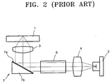
- the conventional optical pick disclosed in Japanese Laid-open Patent Application No. 5-151606 includes a light source 2, a collimating lens 4 which collimates a divergent beam emitted from the light source, a beam splitter 6 which splits an incident light beam, and a holographic reflection mirror 7 which reflects a horizontally incident light beam in a height direction toward the objective lens 3.
- the holographic reflection mirror 7 has a structure where a hologram 7a is formed on the reflection face of a prism 7b which is slanted at an acute angle no greater than 45° with respect to an incident light beam from the light source 2.
- the path of an incident light beam can be perpendicularly changed by a reflection face slanted no greater than 45°. Accordingly, the thickness of an optical pickup in its height direction can be reduced, and its light intensity profile can be made uniform, compared to the case of the reflection mirror 5 slanted at 45° of Figure 1.
- the holographic reflection mirror 7 described above causes chromatic aberration due to the diffraction characteristics of the hologram 5, so it cannot be applied for two wavelengths traveling on the same path. Therefore, the holographic reflection mirror 7 cannot be practically applied to compatible optical pickups using at least two wavelengths.
- a many-sided reflection prism formed as a single body with a plurality of reflection faces which guides a light beam incident through a transmission face in a horizontal direction perpendicular to a height direction by reducing a size of the light beam in the height direction by using a difference in angles between the reflection faces and reflects the guided light beam in the height direction by one reflection face of an angle less than 45° with respect to the horizontal direction.
- the many-sided reflection prism comprises: a first reflection face which reflects the light beam incident through the transmission face downward at an inclined angle with respect to the height and horizontal directions; a plurality of waveguide reflection faces which guide the light beam incident thereon after having been reflected from the first reflection face by reducing the size of the light beam in the height direction; and a second reflection face which has an angle less than 45° with respect to the horizontal direction and reflect the light beam guided by the plurality of waveguide reflection faces.
- the second reflection face has an angle in the range of from about 20° to about 40° with respect to the horizontal direction.
- the plurality of waveguide reflection surfaces are parallel to each other and to the horizontal direction.
- the first reflection face reflects the light beam incident through the transmission face at an angle with respect to the horizontal direction satisfying a total reflection condition. More preferably, the first reflection face reflects the light beam incident thereon through the transmission face at an angle with respect to the height direction such that the light beam reflected from the first reflection face is incident on one waveguide reflection face at an angle satisfying the total reflection condition.
- the many-sided reflection prism it is preferable that a light beam is perpendicularly incident on the transmission face.
- the distance between the plurality of waveguide reflection faces is smaller than a diameter of the light beam incident through the transmission face.
- the many-sided reflection prism is formed as the single body by molding or injection using an optically transparent material.
- an optical pickup comprising: a light generation/detection unit which generates and emits a light beam and receives and detects the light beam reflected from a recording surface of a recording medium; an objective lens which forms a light spot on the recording surface of the recording medium by focusing the light beam incident from the light generation/detection unit; an actuator which actuates the objective lens in a focusing and/or tracking direction; and a many-sided reflection prism which is formed as a single body with a plurality of reflection faces, guides the light beam incident through a transmission face from the light generation/detection unit by reducing a size of the light beam in the height direction while the light beam passes adjacent the bottom of the actuator by using a difference in angles between the reflection faces, and reflects the guided light beam by one reflection face of an angle less than 45° with respect to a horizontal direction perpendicular to the height direction to emit the reflected light beam toward the objective lens.
- the light generation/detection unit comprises: a light source which generates and emits the light beam of a predetermined wavelength; a photodetector which receives the light beam emitted from the light source and reflected from the recording surface of the recording medium; and an optical path changer which changes a traveling path of the light beam such that the light beam emitted from the light sources proceeds toward the recording medium and such that the light beam reflected from the recording surface of the recording medium proceeds toward the photodetector.
- the optical path changer is of a beam splitter type.
- the optical path changer may be a hologram optical element which selectively transmits straight or diffracts/transmits the light beam depending on the direction from which the light beam is incident, and the light source, the photodetector, and the optical path changer may be integrated into a light module.
- the light generation/detection unit comprises: a plurality of light sources, each of which emits a light beam of a different wavelength; a plurality of photodetectors, each of which receives the light beam emitted from a light source and reflected from the recording surface of a recording medium; and an optical path changing unit which changes the traveling path of the light beam such that the light beam emitted from the light source proceeds toward the recording medium and such that the light beam reflected from the recording surface of the recording medium proceeds toward the photodetector, and the optical pickup is compatible with the recording media having different formats.
- the plurality of light sources may comprise a first light source which emits a light beam of a relatively short wavelength and a second light source which emits a light beam of a relatively long wavelength
- the plurality of photodetectors may comprise a first photodetector which detects the light beam emitted from the first light source and reflected from the recording surface of a recording medium and a second photodetector which detects the light beam emitted from the second light source and reflected from the recording surface of the other recording medium
- the optical path changing unit may comprise a first optical path changer which changes the traveling path of the light beam emitted from the first light source, a second optical path changer which changes the traveling path of the light beam emitted from the second light source, and a third optical path changer which changes the traveling paths of the light beams emitted from the first and second light sources.
- the first light source emits the light beam having a wavelength of about 650 nm
- the second light source emits the light beam having a wavelength of about 780 nm
- the first and second optical path changers comprises a hologram optical element which selectively transmits straight or diffracts/transmits the light beam according to the direction from which the light beam is incident
- the first light source, the first photodetector, and the first optical path changer are integrated into a light module
- the second light source, the second photodetector, and the second optical path changer are integrated into a light module
- the third optical path changer is a wavelength selective beam splitter which selectively transmits or reflects the light beams emitted from the first and second light sources according to the wavelength of the light beams.
- an optical pickup compatible with recording media having a plurality of formats, the optical pickup comprising: a light generation/detection unit which generates and emits light beams of a plurality of wavelengths and receives and detects the light beams reflected from a recording surface of the recording media; an objective lens which forms a light spot on the recording surface of a recording medium by focusing the light beam incident from the light generation/detection unit; an actuator which actuates the objective lens in a focusing and/or tracking direction; and a compound reflection prism which comprises a plurality of prisms, guides the light beam incident from the light generation/detection unit by reducing a size of the light beam in a height direction while the light beam passes adjacent the bottom of the actuator by using a difference in angles between faces of the plurality of prisms, and reflects the guided light beam by one face of an angle less than 45° with respect to a horizontal direction perpendicular to the height direction to emit the reflected light beam
- the compound reflection prism comprises: a first prism having a first transmission face and a first face which reflects the light beam incident through the first transmission face downward at an inclined angle with respect to the height and horizontal directions; and a second prism having second and third faces which are arranged in the height direction spaced a predetermined distance that is smaller than a diameter of the light beam incident on the first transmission face and which alternately reflect the light beam incident thereon after having been reflected from the first face, and a fourth face which has an angle less than 45° with respect to the horizontal direction and reflects the light beam incident thereon after having been reflected from the third face.
- the fourth face of the second prism has an angle in the range of from about 20° to about 40° with respect to the horizontal direction.
- the second and third faces of the second prism are parallel to each other.
- the second prism is a rhomboidal prism where the second, third, and fourth faces and an opposite face to the fourth face form a rhombus structure.
- the compound reflection prism further comprises a third prism between the first and second prisms which allows the light beam reflected from the first face of the first prism to proceed straight and enter the second prism. More preferably, the third prism is a triangular prism having a right triangular structure. It is preferable that the first prism is a triangular prism having an isosceles triangular structure oriented at a predetermined angle with respect to the horizontal direction.
- first and second prisms are constructed such that total internal reflection occurs at the first, second, and third faces.
- Figure 4 schematically shows the path of a light beam in the many-sided reflection prism of Figure 3.
- the first embodiment of the optical pickup according to the present invention includes a light generation/detection unit which generates and emits a light beam of a predetermined wavelength and detects the light beam reflected from a recording surface 10a of a recording medium 10, an objective lens 30 which forms a light spot on the recording surface 10a of the recording medium 10 by focusing the light beam incident from the light generation/detection unit, an actuator 31 which drives the objective lens 30 in a focusing and/or tracking direction, and a many-sided reflection prism 20.
- the light generation/detection unit includes a light source 11 which emits light of a predetermined wavelength and a photodetector 39 which receives the light beam reflected from the recording medium 10 and detects an information signal and an error signal.
- the optical pickup may comprise an edge emitting laser or a vertical cavity surface emitting laser as the light source 11.
- the light generation/detection unit further includes an optical path changer which changes the travelling path of a light beam between the light source 11 and the many-sided reflection prism 20.
- the optical path changer can be formed of a polarizing beam splitter 15 which transmits or reflects a light beam according to the polarization of the light beam, and a wave plate 17 which changes the polarization of the incident light beam.
- the wave plate 17 is formed of, preferably a quarter-wave plate with respect to a wavelength of the light beam emitted from the light source.
- the optical pickup may comprise a beam splitter which transmits and reflects a light beam in a predetermined ratio, as the optical path changer.
- the optical pickup according to the present invention further includes a collimating lens on the optical path between the light source 11 and the many-sided reflection prism 20 for collimating the divergent beam emitted from the light source 11.
- a collimating lens 13 is arranged as shown in Figure 3
- a condensing lens 33 is further disposed on the optical path between the optical path changer and the photodetector 39 to condense the light beam reflected from the recording medium 10 and sequentially transmitted through the objective lens 30, the many-sided reflection prism 20, and the optical path changer toward the photodetector 39.
- An astigmatism lens unit including a cylindrical lens which induces astigmatism to an incident light beam, and a yoke lens 38 which slightly diverges the incident light beam to enable the photodetector 39 to receive a light beam of an appropriate size can be further disposed on the optical path between the optical path changer and the photodetector 39 such that a focus error signal can be detected using an astigmatism method.
- reference numeral 19 denotes a front photodetector for monitoring the quantity of light emitted from the light source 11.
- Figure 3 shows an example of arrangement of the optical elements described above, which can minimize the thickness of the optical pickup according to the present invention in a height direction hi .
- the height direction hi refers to the direction of the optical axis of the objective lens 30.
- the objective lens 30 has a NA of 0.6 or greater and has a working distance as short as possible, for the implementation of a slim optical pickup.
- the objective lens 30 is controlled in focusing and tracking directions by the actuator 31.
- the basic structure of the actuator 31 is well known in the technical field, and thus a detailed description and illustration will be not provided here.
- Figure 5 is a perspective view of the many-sided reflection prism 20 according to the present invention.
- Figure 6 is a plan view of Figure 5
- Figure 7 is a front view of Figure 5.
- Figures 6 and 7 show embodiments of the design of the many-sided reflection prism 20 according to the present invention.
- the many-sided reflection prism 20 is formed as a single body with many reflection faces, which proceeds an incident light beam from the light source 11 by reducing the size of the light beam in the height direction hi by using a difference in angles between the reflection faces, and then reflects the light beam by a reflection face having an angle less than 45° with respect to the horizontal direction ho perpendicular to the height direction h1 to emit the light beam in the height direction hi.
- the height direction hi and the horizontal direction ho are perpendicular to the incident direction.
- the incident direction is parallel to the z-axis of an x-y-z orthogonal coordinates system
- the horizontal direction ho and the height direction hi are parallel to the x-axis and the y-axis, respectively.
- the many-sided reflection prism 20 includes a transmission face 21 on which the light beam emitted from the light source 11 is perpendicularly incident, a first reflection face 23 which reflects the light beam incident through the transmission face 21 at a predetermined angle with respect to the height direction hi and the horizontal direction ho, first and second waveguide reflection faces 25 and 27 which guide the light beam incident thereon after being reflected from the first reflection face 23 in the horizontal direction ho by alternately reflecting the same, and a second reflection face 29 which reflects the light beam incident from the second waveguide reflection face 27 in the height direction hi .
- the transmission face 21 is formed such that it can transmit all of the light beam incident thereon.
- the first reflection face 22 is formed such that it can reflect the incident light beam at an angle with respect to the horizontal direction ho to satisfy a total internal reflection condition and such that it can reflect the incident light beam at an angle, for example, 30 ⁇ 10°, with respect to the height direction h1 so that the light beam reflected by the first reflection face 22 is incident on the first waveguide reflection face 25 to satisfy the total reflection condition.
- the first reflection face 23 when the first reflection face 23 is slanted at 45° with respect to the horizontal direction ho and is formed to reflect an incident light beam at 30° with respect to the height direction hi, the light beam is reflected from the first reflection face 23 to proceed in the horizontal direction ho, slanted at about 30° with respect to the height direction hi. Accordingly, when the first waveguide reflection face 25 is parallel to the horizontal direction ho, the light beam reflected from the first reflection face 23 is incident on the first waveguide reflection face 25 at an incident angle of 60° and totally reflected by the same.
- n1 of medium of the many-sided reflection prism 20 1.5
- n2 of the outside of the many-sided reflection prism 20 i.e, a refractive index of air
- the first reflection face 23 when the first reflection face 23 is formed such that it satisfies the condition of total reflection in the horizontal direction ho , and a light beam can be incident on the first waveguide reflection face 25 at an angle satisfying the condition of total reflection at the first waveguide reflection face 25, the light beam incident on the first reflection face 23 after perpendicularly having passed the transmission face 21 is totally reflected from the first reflection face 23, and the totally reflected light beam is incident on the first waveguide reflection face 24 at an angle satisfying the total reflection condition.
- first and second waveguide reflection faces 25 and 27 are parallel to each other and at the same time are parallel to the horizontal direction ho , and the second waveguide reflection face 27 is positioned above the first waveguide reflection face 25 in the height direction hi.
- the angle at which the light beam reflected from the first waveguide reflection face 25 is incident on the second waveguide reflection face 27 is the same as that at which the light beam from the first reflection face 23 is incident on the first waveguide reflection face 25, and thus the light beam incident on the second waveguide reflection face 27 is totally reflected, as from the first waveguide reflection face 25, and incident on the second reflection face 29.
- the first and second waveguide reflection faces 25 and 27 multiple-reflects the light beam to a height smaller than a diameter of the light beam incident on the transmission face 21 to guide the light beam along the horizontal direction ho.
- the distance in the height direction h1 between the first and second waveguide reflection faces 25 and 27 facing each other is smaller than a diameter of the light beam perpendicularly incident on the transmission face 21 from the light source 11.
- the light beam incident on the many-sided reflection prism 20 according to the present invention can be guided along the horizontal direction ho while being reduced in the size of the light beam in the height direction h1 compared to the light beam perpendicularly incident on the transmission face 21, thereby enabling a height reduction of the optical pickup.
- the light beam is illustrated in Figure 7 as being reflected once from each of the first and second waveguide reflection faces 25 and 27, this illustration is for exemplary purpose only.
- the length of the first and second waveguide reflection faces 25 and 27 can be adjusted to comply with the requirement for waveguide distance in the horizontal direction ho , so that total reflection occurs, for example, two or more times from each of the first and second waveguide reflection faces 25 and 27.
- the structure of the optical pickup can be modified to include a plurality of first waveguide reflection faces 25 and a plurality of second waveguide reflection faces 27.
- the second reflection face 29 has an angle less than 45° with respect to the horizontal direction ho .
- the second reflection face 29 has an angle of 30 ⁇ 10°, i.e., from about 20° to about 40°, with respect to the horizontal direction ho .
- the angle at which the light beam reflected from the second waveguide reflection face 27 is incident on the second reflection face 29 does not comply with the total internal reflection condition. Accordingly, it is preferable to coat the second reflection face 29 so that a light beam is totally reflected therefrom.
- the many-sided reflection prism 20 according to the present invention described above has, for example, the specification described above with reference to Figures 5 through 7, so that the light beam is incident on the first waveguide reflection face 25 from the first reflection face 23 at an incident angle of 60°, and the second reflection face 29 is slanted at 30° with respect to the horizontal direction ho , the light beam proceeded to the many-sided reflection prism 20 after having been perpendicularly incident on the first transmission face 21 parallel to the incident direction is changed to be perpendicular in direction by the second reflection face 19, perpendicularly transmits the second waveguide reflection face 29, and proceeds parallel to the height direction hi.
- a separate transmission face can be additionally provided to emit the light beam reflected from the second reflection face 19 toward the objective lens 30.
- the variation in light beam diameter in the many-sided reflection prism 20 is as follows. For example, when the original light beam incident on the first transmission face 21 from the light source 11 has a diameter of 3.8 mm, the diameter of the light beam on the first waveguide reflection face 25 becomes about 7.5 mm, which is almost twice the original. After total internal reflection from the first waveguide reflection face 25, the light beam undergoes total internal reflection from the second waveguide reflection face 29 in the same condition as from the first waveguide reflection face 25, and then is incident on the second reflection face 29. As the second reflection face 29 is slanted at 30° with respect to the horizontal direction ho , the light beam is incident on the second reflection face 19 at an incident angle of 30°.
- the diameter of the light beam is restored to the original of 3.8 mm, and the light beam is emitted in the height direction hi.
- the diameter of the light beam proceeding toward the objective lens 30 after having been reflected from the second reflection face 29 can be varied by the angle of the second reflection face 29 with respect to the horizontal direction ho .
- the many-sided reflection prism 20 according to the present invention described above has the optimal specification such that the diameter of the light beam travelling through the many-sided reflection prism 20 after having been emitted from the light generation/detection unit is maintained to be the same as when incident on the many-sided reflection prism 20 from the light generation/detection unit or is enlarged and such that the optical pickup has a minimal thickness.
- the many-sided reflection prism 20 according to the present invention is arranged in an optimal position.
- the many-sided reflection prism 20 has a structure to guide the light beam between the first and second waveguide reflection faces 25 and 27 by reducing the size of the light beam in the height direction hi. Also, the distance between the first and second waveguide reflection faces 25 and 27 is smaller than the diameter of the light beam incident on the transmission face 21 from the light generation/detection unit. Thus, the top side of the transmission face 21 protrudes further than the second waveguide reflection face 27 in the height direction hi. Therefore, to manufacture slimmer compatible optical pickups, it is preferable that the many-sided reflection prism 20 is arranged such that only a portion corresponding to the second waveguide reflection face 29 is positioned close to the bottom of the actuator 31 and such that the actuator 31 is constructed for that arrangement.
- an effective thickness of the many-sided reflection prism 20, which affects a thickness of the optical pickup is substantially the distance between the first and second waveguide reflection faces 25 and 27.
- at least one portion of the objective lens 30 is positioned to be lower than the light beam emitted from the light generation/detection unit and incident on the many-sided reflection prism 20.
- the thickness of the optimised many-sided reflection prism 20 at the first and second waveguide reflection faces 25 and 27 is dependent upon the angle of the second reflection face 29 with respect to the horizontal direction ho . Therefore, the thickness of the optical pickup in the height direction hi is reducible according to a reduction in the angle of the second reflection face 29 with respect to the horizontal direction ho .
- the angle of the second reflection face 29 with respect to the horizontal direction ho is adjustable within a range of 30 ⁇ 10°.
- the above-described complex structure of the many-sided reflection prism 20 can be manufactured as a single body by molding or injection using a transparent material such as glass or plastic. Accordingly, the many-sided reflection prism 20 according to the present invention is suited for low-cost mass production.
- the many-sided reflection prism 20 is applied to an actual optical pickup, the height of the optical pickup is reduced, for example, by 30-50% of that of general optical pickups, and thus it contributes to producing slim optical recording/reproducing apparatuses.
- Figure 7 shows that when the height of an optical system determined by the diameter of the optical beam incident on the transmission face 21 is 4.3 mm, the height of the optical system below the objective lens 30 can be reduced to 2.2 mm by using the many-sided reflection prism 20 according to the present invention having the second reflection face 29 slanted at 30° with respect to the horizontal direction ho .
- a light beam of a relatively large diameter incident on the many-sided reflection prism 20 from the light generation/detection unit passes adjacent the bottom of the actuator 31 at a distance further from a recording medium than at least a portion of the incident light beam, and is restored to the original diameter after being reflected from the second reflection face 29.
- the many-sided reflection prism 20 according to the present invention described above is applied to an optical pickup, after a light beam incident on the transmission face 21 of the many-sided reflection prism 20 passes adjacent the bottom of the actuator 31 at a distance further from a recording medium than at least a portion of the incident light beam, the light beam is restored to the original diameter after being reflected from the second reflection face 29 of the many-sided reflection prism 20 and enters the objective lens 30.
- the above-described many-sided reflection prism 20 according to the present invention can lower the light beam incident position on the transmission face 20, compared to the compound reflection prism suggested by the inventor in European Patent Application No. 02250219.9 (corresponding to Korean Patent Application No. 2001-23343) and entitled "Compound reflection Prism and Optical Pickup using the Same". Accordingly, the many-sided reflection prism 20 according to the present invention can further reduce the height of an optical system compared to using the compound reflection prism taught by European Patent Application No. 02250219.9 and can ensure a greater tolerance for the light beam path in the many-sided reflection prism 20, i.e., the surrounding of the effective diameter of the light beam, in the manufacturing process.
- the reason that the many-sided reflection prism 20 according to the present invention can achieve a greater reduction in the height of the optical system, compared to when the compound reflection prism suggested by European Patent Application No. 02250219.9 is applied, is as follows. Since the many-sided reflection prism 20 according to the present invention is formed as a single polyhedron, the transmission face 21 can be extended beyond the region of the third prism (130 in Figure 14) of the compound reflection prism suggested by European Patent Application No. 02250219.9.
- the light beam incident position on the many-sided reflection prism 20 according to the present invention can be lowered such that the base line of a light beam incident from the light source 11 almost meets the base of the many-sided reflection prism 20, i.e., the bottom side of the transmission face 21.
- a light beam emitted from the light source 11 is collimated by the collimating lens 13.
- the collimated light beam is substantially orthrogonally incident on the transmission face 21 of the many-sided reflection prism 20 according to the present invention via the optical path changer.
- the light beam incident into the many-sided reflection prism 20 through the transmission face 21 undergoes total internal reflection by the first reflection face 23, travels downward at an inclined angle with respect to the horizontal direction ho , and is incident on the first waveguide reflection face 25 at an incident angle, for example, 60° ,satisfying the total reflection condition.
- the light beam is totally reflected alternately from the first and second waveguide reflection faces 25 and 27 which are spaced a predetermined distance that is smaller than the diameter of the light beam incident on the first transmission face 21, so that the light beam is guided along the horizontal direction ho with a reduced size in the height direction hi .
- the light beam is restored to the original diameter or is enlarged to be greater than the original diameter after being reflected from the second reflection face 29 and proceeds to the objective lens 30.
- the light beam is focused as a light spot on the recording surface 10a of the recording medium 10 by the objective lens 30.
- the light beam reflected from the recording surface 10a is incident on the optical path changer via the objective lens 20 and the many-sided reflection prism 20 along the optical path opposite to the above, reflected by the optical path changer, and received by the photodetector 39.
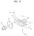
- Figure 8 is a perspective view of a second embodiment of an optical pickup using the many-sided reflection prism 20 according to the present invention.
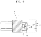
- Figure 9 is a schematic diagram of a light module of Figure 8.
- the same reference numerals as those of Figure 3 denote the same elements as in Figure 3, and thus descriptions thereof will be not repeated here.
- the light generation/detection unit includes a single light module 40, for example, a hologram laser module in which a photodetector is mounted on a semiconductor laser substrate.
- the light module 40 may includes a light source 41, a hologram optical element (HOE) 45, and a photodetector 49.
- HOE hologram optical element
- the light source 41 emits a light beam of a 650-nm wavelength.
- the HOE 45 acting as an optical path changer is formed to selectively transmit straight or diffract/transmit the light beam depending on the direction from which the light beam is incident.
- the HOE 45 directly transmits the light beam incident from the light source 40 and diffracts/transmits the light beam incident after having been reflected from the recording medium 10 so that the light beam proceeds toward the photodetector 49 mounted at one side of the light source 41, as shown in Figure 9.
- Figure 9 shows a structural example of the light module 40. It is appreciated that the structure of the light module 40 according to the present invention is not limited to Figure 9.
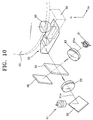
- Figure 10 is a perspective view of a third embodiment of an optical pickup using the many-sided reflection prism 20 according to a third embodiment of the present invention.
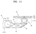
- Figure 11 is a schematic diagram showing the path of a light beam in the many-sided reflection prism of Figure 10.
- the third embodiment of the optical pickup according to the present invention has an optical structure compatible with recording media 50 having different formats, in which the light generation/detection unit includes a first light module 51, a second light module 61, and an optical path changer. It is preferable that the first light module 51 emits a first light beam 51a having a wavelength suitable for a first recording medium 51a having a relatively small thickness.
- a hologram laser module for DVDs can be used as the first light module 51. In this case, a first light beam 51a of a 650-nm wavelength is emitted from the first light module 51.
- the second light module emits a second light beam 61a having a wavelength suitable for a second recording medium 50b having a relatively large thickness.
- a hologram laser module for CDs can be used as the second light module 61.
- a second light beam 61a of a 780-nm wavelength is emitted from the second light module 61.
- DVD- and CD-hologram laser modules are used as the first and second light modules 51 and 61, respectively, as described above, the third embodiment of the optical pickup according to the present invention is compatible with CD family and DVD family recording media 50.
- the detailed structures of the first and second light modules 51 and 61, except for their wavelength characteristics, can be inferred from Figure 9, and thus descriptions thereof will be not repeated here.
- a wavelength selective beam splitter 55 which selectively transmits and reflects the first and second light beams 51a and 61a emitted from the respective first and second light modules 51 and 61 depending on the wavelength and directs the first and second light beams 51a and 61 to enter the many-sided reflection prism 20 may be comprised as the optical path changer.
- the wavelength selective beam splitter 55 can be provided such that it transmits most of the first light beam 51 of a 650-nm wavelength emitted from the first light modules 51 and totally reflects the second light beam 61a of a 650-nm wavelength emitted from the second light module 61.
- a front photodetector 56 which monitors the quantity of light emitted from the first light module 51 by receiving a portion of the first light beam 51a reflected from the wavelength selective beam splitter 55 is additionally disposed at one side of the wavelength selective beam splitter 55.
- the wavelength selective beam splitter 55 can be constructed such that it reflects and transmits a portion of each of the first and second light beams 51a and 61a.
- the front photodetector 56 can be used to monitor the quantity of light emitted from both of the first and second light modules 51 and 61.
- the light generation/detection unit is described and illustrated here as including the first and second light modules 51 and 61, it is appreciated that the light generation/detection unit is not limited to this structure and can be modified into a variety of compatible optical structures.
- the light generation/detection unit of a compatible optical pickup according to the present invention may have an optical structure including, instead of the first and second light modules 51 and 61, a pair of light sources which generate and emit the first and second light beams 51a and 61a having different wavelengths, a pair of photodetectors which receive the light emitted from the pair of light sources and reflected from the recording surface of the recording medium 50, an optical path changer which changes the traveling path of the first light beam 51a emitted from one light source, and another optical path changer which changes the traveling path of the second light beam 61a emitted from the other light source.
- the light generation/detection unit of a compatible optical pickup according to the present invention can be modified to be compatible with more than three recording media having different
- reference numeral 52 denotes a reflection mirror
- reference numeral 53 denotes a collimating lens which collimates the first light beam 51a diverging from the first light module 51
- reference numeral 63 denotes a collimating lens which collimates the second light beam 61a diverging from the second light module 61.
- Figure 10 shows an optical arrangement of the optical pickup according to the third embodiment of the present invention in which the constituent optical elements of the light generation/detection unit are arranged in such a way that the thickness of the optical pickup in the height direction h1 is minimized.
- the objective lens 60 has a NA of 0.6 or greater and that the objective lens 60 is optimized to form a light spot on the recording surface of each of the first and second recording media 50a and 50b having different thicknesses without causing aberration with respect to the first and second light beams 51a and 61a having different wavelengths.
- the objective lens 60 to have a working distance as short as possible. The objective lens 60 is controlled in the focusing and tracking directions by the actuator 65.
- an optical pickup according to the third embodiment of the present invention is constructed to be compatible with CD family and DVD family recording media, and a DVD family first recording medium 50a is loaded, the first light module 51 is driven to emit a first light beam 51a. Also, when a CD family second recording medium 50b is loaded, the second light module 61 is driven to emit a second light beam 61a.
- the first or second light beam 51a or 61a emitted from the first or second light module 51 or 61 is incident on the wavelength selective beam splitter 55.
- the first or second light beam 51a or 61a of a predetermined diameter transmitted through or reflected from the wavelength selective beam splitter 55 is substantially perpendicularly incident on the transmission face 21 of the many-sided reflection prism 20 and enters the objective lens 60 via substantially the same optical path in the many-sided reflection prism 20 as described with reference to Figure 4.
- the first or second light beam 51a or 61a incident on the objective lens 60 is focused by the objective lens 60 to form a light spot on the recording surface of the first or second recording medium 50a or 50b.
- the first or second light beam 51a or 61a reflected from the recording surface of the first or second recording medium 50a or 50b is incident on the wavelength selective beam splitter 55 through the objective lens 60 and the many-sided reflection prism 20 via the optical path opposite to the above and transmits through or is reflected from the wavelength selective beam splitter 55.
- the transmitted first light beam 51a or the reflected second light beam 61a is incident on the first or second optical recording module 51 or 61 and diffracted/transmitted at the HOE of the first or second light module 51 or 61 so that it is received by the photodetector.
- an optical pickup according to a fourth embodiment of the present invention which is compatible with recording media 50 having different formats includes a compound reflection prism 100 suggested by European Patent Application No. 02250219.9 described above, instead of the many-sided reflection prism 20 according to the present invention.
- the same reference numerals as those in Figure 10 denote the elements having substantially the same functions as those in Figure 10, and thus descriptions thereof will be not repeated here.
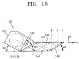
- the compound reflection prism 100 is constructed to include first and second prisms 120 and 140.
- the compound reflection prism 100 reduces the size the first and second light beam 51a and 61a in the height direction hi , which are incident from the respective first and second light modules 51 and 61 substantially parallel to the horizontal direction ho perpendicular to the height direction hi, by using a difference in angles between the first and second prisms 120 and 140.
- the compound reflection prism 100 After guiding the first and second light beams 51a and 61a along the horizontal direction ho perpendicular to the height direction hi with a reduced size in the horizontal direction ho , the compound reflection prism 100 reflects the first and second light beams 51a and 61a by a face of the second prism 140 to emit the first and second light beams 51a and 61a in the height direction h1 .
- the compound reflection prism 100 further includes a third prism 130 between the first and second prisms 120 and 140 for enabling the light beam reflected from a first face 125 of the first prism 120 to proceed straight without refraction and enter the second prism 140.
- the first prism 120 is a triangular prism with a first transmission face 121, a first face 125 for reflecting the light beam incident through the first transmission face 121 downward at an inclined angle, and an opposite face to the second prism 140 that have an isosceles triangular structure, preferably an isosceles right triangular structure.
- the first and second light beams 51a and 61a from the respective first and second light modules 51 and 61 are perpendicularly incident on the first transmission face 121.
- the first face 125 is constructed such that it totally reflects the incident first and second light beams 51a and 61a with respect to the horizontal direction ho and reflects the same at an angle of, for example, 30° with respect to the height direction h1 at which total internal reflection occurs.
- the first prism 120 is constructed to have, for example, an isosceles right triangular structure
- the light beam perpendicularly incident through the first transmission face 121 is incident on the first face 125 at an incident angle of 45° so that the light beam incident through the first transmission face 121 can be totally internally reflected by the first face 125.
- the second prism 140 includes a second face 141 which totally internally reflects the light beam incident into the second prism 140 after having been reflected by the first face 125 of the first prism 120 upward at an inclined angle, a third face 145 which is separated above from the second face 141 and totally internally reflects the light beam incident from the second face 141, wherein the distance between the second and third faces 141 and 145 permits a reduction in the size of the light beam in the height direction h1 , and a fourth face 149 which reflects the light beam incident thereon after having been reflected from the third face 145 in the height direction hi.
- the distance between the second and third faces 141 and 145 arranged in the height direction hi facing each other is smaller than a diameter of the light beam incident on the first transmission face 121 of the first prism 121, as in the case of the many-sided reflection prism 20 according to the present invention. In this manner, by reducing the distance between the second and third faces 141 and 145, the size of the light beam in the height direction hi can be reduced to guide the light beam within the compound reflection prism 100 along the horizontal direction ho . It is preferable that the second and third faces 141 and 145 are parallel to each other.
- the fourth face 149 has an angle less than 45°, preferably of 30 ⁇ 10° (i.e., in the range of from about 20° to about 40°), with respect to the horizontal direction ho . Due to the structure of the second prism 140, the angle at which the light beam reflected from the third face 145 is incident on the fourth face 149 fails to satisfy the total internal reflection condition. Therefore, it is preferable the fourth face 149 is coated to be a reflective surface, more preferably a totally reflective surface.
- the second prism 140 is a rhomboidal prism where the second, third, and fourth faces 141 and 145 and 149 and an opposite face to the fourth face 149 form a rhombus structure.
- the third prism 130 allows the light beam reflected from the first face 125 of the first prism 120 to directly travel without refraction and enter the second prism 140.
- the third prism 130 may be a triangular prism having a right triangular structure.
- the first transmission face 121 of the first prism 120 has an approximately rectangular structure, it is preferable that the first prism 120 is slanted at an angle, i.e., an angle corresponding to the vertical angle of the third prism 120 (the angle between the faces adjacent to the first and second prisms 120 and 140), with respect to the horizontal direction ho .
- the first prism 120 has a right isosceles triangular structure arranged at an inclined angle of 20° with respect to the horizontal direction ho
- the third prism 130 is a triangular prism having a right triangular structure with a 30° vertical angle
- the second prism 140 is a rhomboidal prism where the fourth face 149 has an angle of 30° with respect to the horizontal direction ho .
- the light beam incident on the first face 125 from the first transmission face 121 is totally internally reflected and travels straight to enter the second prism 140.
- the light beam incident on the second prism 140 enters the second face 141 at an inclined angle of 30° (i.e., at an incident angle of 60°). Therefore, the incident light beam is totally internally reflected by the second face 141 and travels toward the third face 145.
- the fourth face 149 reflects the incident light beam in the height direction hi .
- the compound reflection prism 100 has a structure of guiding the incident light beam between the second and third faces 141 and 145 of the second prism 140 by reducing the size of the light beam in the height direction h1 .
- the first prism 120 of the compound reflection prism 100 protrudes further than the second prism 140 in the height direction hi. Therefore, to manufacture much slimmer compatible optical pickups, it is preferable that the compound reflection prism 100 is arranged such that the second prism 140, in particular only a portion corresponding to the third face 145 of the second prism 140, is positioned close to the bottom of an actuator 65 and such that the actuator 31 is constructed for that arrangement.
- an effective thickness of the compound reflection prism 100 which affects a thickness of the optical pickup, is substantially the distance between the second and third faces 141 and 145.
- at least one portion of the objective lens 30 is positioned lower than a portion of the light beam incident on the compound reflection prism 100 from the light generation/detection unit.
- the thickness of the optimised compound reflection prism 100 at the second prism 140 is dependent upon the angle of the fourth face 149 with respect to the horizontal direction ho . Therefore, the thickness of the optical pickup in the height direction hi is reducible according to a reduction in the angle of the fourth face 149 with respect to the horizontal direction ho .
- the fourth face 149 has an angle of 30 ⁇ 10° with respect to the horizontal direction ho .
- the first and second light beams 51a and 61a each of a relatively large diameter incident on the compound reflection prism 100 from the light generation/detection unit passes adjacent the bottom of the actuator 65 at a distance further from a recording medium than at least a portion of the incident light beam, and is restored to their original diameter after being reflected from the fourth face 149 of the second prism 140.
- the compound reflection prism 100 having the structure described above, for example, including the first prism 120 having an isosceles right triangular structure with the first transmission face 121 on which a light beam is incident from the light generation/detection unit and which is approximately rectangular, the second prism 140 having a rhomboidal prism structure, and the third prism 130 positioned between the first and second prisms 120 and 140, which are rectangular prisms having a right triangular structure, the first and second light beams 51a and 61a are incident on a region of the first transmission face 121 considerably far away from the base of the compound reflection prism 100, i.e., its lower end parallel to the horizontal direction ho , compared to the many-sided reflection prism 10 according to the present invention, to prohibit the first and second light beams 51a and 61b from entering a region of the third prism 130. Therefore, when the compound reflection prism 100 as described above is used, the thickness of the optical system in the height direction is slightly larger than when using the many-sided reflection pris
- an optical pickup according to the above-described embodiments of the present invention has a thickness reduced by 30-50% by using the many-sided reflection prism 20 according to the present invention or the compound reflection prism 100 taught by the applicant in European Patent Application No. 02250219.9, and can contribute to producing slim optical recording/reproducing apparatuses.
- the many-sided reflection prism 20 according to the present invention can be formed as a single body by molding or injection using a transparent material such as glass or plastic. Accordingly, the many-sided reflection prism 20 according to the present invention is suited for low-cost mass production.
- the height of the optical system can be reduced regardless of the wavelength used without reducing light beam size, and slim-sized optical pickups can be implemented.
Landscapes
- Physics & Mathematics (AREA)
- Optics & Photonics (AREA)
- General Physics & Mathematics (AREA)
- Optical Head (AREA)
- Optical Elements Other Than Lenses (AREA)
- Diffracting Gratings Or Hologram Optical Elements (AREA)
Applications Claiming Priority (4)
| Application Number | Priority Date | Filing Date | Title |
|---|---|---|---|
| KR2001026032 | 2001-05-12 | ||
| KR20010026032 | 2001-05-12 | ||
| KR1020010061036A KR100850701B1 (ko) | 2001-05-12 | 2001-09-29 | 다면 반사프리즘 및 광픽업장치 |
| KR2001061036 | 2001-09-29 |
Publications (3)
| Publication Number | Publication Date |
|---|---|
| EP1256945A2 true EP1256945A2 (fr) | 2002-11-13 |
| EP1256945A3 EP1256945A3 (fr) | 2006-06-14 |
| EP1256945B1 EP1256945B1 (fr) | 2008-02-06 |
Family
ID=26639069
Family Applications (1)
| Application Number | Title | Priority Date | Filing Date |
|---|---|---|---|
| EP02253263A Expired - Lifetime EP1256945B1 (fr) | 2001-05-12 | 2002-05-09 | Prisme à réflexion avec plusieurs surfaces latérales et tête de lecture optique |
Country Status (5)
| Country | Link |
|---|---|
| US (1) | US7177260B2 (fr) |
| EP (1) | EP1256945B1 (fr) |
| JP (1) | JP2003035807A (fr) |
| CN (1) | CN1235068C (fr) |
| TW (1) | TW591248B (fr) |
Cited By (2)
| Publication number | Priority date | Publication date | Assignee | Title |
|---|---|---|---|---|
| EP1524654A3 (fr) * | 2003-10-16 | 2007-10-24 | Nec Corporation | Dispositif à tête optique et dispositif d'enregistrement et de reproduction optique |
| WO2009032547A1 (fr) * | 2007-09-06 | 2009-03-12 | The Boeing Company | Appareil à prisme d'inspection optique éclairé |
Families Citing this family (12)
| Publication number | Priority date | Publication date | Assignee | Title |
|---|---|---|---|---|
| JP4644471B2 (ja) * | 2004-11-10 | 2011-03-02 | 株式会社日立メディアエレクトロニクス | 光ピックアップ及び光ディスクシステム |
| JP2007220166A (ja) * | 2006-02-14 | 2007-08-30 | Sony Corp | 光ピックアップ、光ディスク装置及び立上プリズム |
| JP2008004250A (ja) * | 2006-05-24 | 2008-01-10 | Sony Corp | 光ディスク装置及び光ピックアップ |
| JP2007317284A (ja) * | 2006-05-25 | 2007-12-06 | Hitachi Ltd | 光ディスク装置 |
| JP4784410B2 (ja) * | 2006-06-22 | 2011-10-05 | ソニー株式会社 | 光ピックアップ及び光ディスク装置 |
| JP4776601B2 (ja) * | 2007-09-14 | 2011-09-21 | 三洋電機株式会社 | 光ピックアップ装置 |
| JP2011150767A (ja) * | 2010-01-25 | 2011-08-04 | Hitachi Media Electoronics Co Ltd | 光学ヘッド |
| CN106500891B (zh) * | 2016-11-29 | 2022-08-16 | 北京杰福科技有限公司 | 玻璃表面应力检测装置以及用于其的检测棱镜 |
| US20180321736A1 (en) * | 2017-05-03 | 2018-11-08 | Intel Corporation | Beam guiding device |
| EP3676631A4 (fr) * | 2017-09-05 | 2021-04-14 | Waymo LLC | Guide d'ondes partagé pour émetteur et récepteur lidar |
| FI20215647A1 (en) * | 2020-07-31 | 2022-02-01 | Kaahre Jan | Optical multimeter |
| US20220091398A1 (en) * | 2020-09-24 | 2022-03-24 | Apple Inc. | Telephoto Camera with a Stationary Optics Assembly |
Family Cites Families (11)
| Publication number | Priority date | Publication date | Assignee | Title |
|---|---|---|---|---|
| US4333173A (en) * | 1979-06-15 | 1982-06-01 | Hitachi, Ltd. | Optical information processor with prismatic correction of laser beam shape |
| US5135791A (en) * | 1985-12-06 | 1992-08-04 | Sumitomo Chemical Company, Limited | Optical device |
| US5513164A (en) * | 1992-09-11 | 1996-04-30 | Kabushiki Kaisha Toshiba | Optical recording and reproducing apparatus |
| JPH06302005A (ja) * | 1993-04-20 | 1994-10-28 | Canon Inc | 光学ヘッド装置 |
| JPH0721580A (ja) | 1993-06-30 | 1995-01-24 | Hitachi Ltd | 光ヘッド並びにこれを用いた光ディスク装置およびこれに用いる伝搬型プリズム |
| JPH1116195A (ja) * | 1997-06-24 | 1999-01-22 | Toshiba Corp | 光ディスク装置 |
| US6327238B1 (en) * | 1997-08-29 | 2001-12-04 | Matsushita Electric Industrial Co., Ltd. | Optical disk device |
| JP3542065B2 (ja) * | 1997-08-29 | 2004-07-14 | 松下電器産業株式会社 | 光ディスク装置 |
| TW432378B (en) * | 1999-04-13 | 2001-05-01 | Ind Tech Res Inst | A multiple-wavelength read/write pickup head for DVD |
| KR100813943B1 (ko) * | 2001-04-30 | 2008-03-14 | 삼성전자주식회사 | 복합 반사프리즘 및 이를 채용한 광픽업장치 |
| KR100765741B1 (ko) * | 2001-07-26 | 2007-10-15 | 삼성전자주식회사 | 일 매의 렌즈로 된 고개구수의 대물렌즈 및 이를 채용한광픽업장치 |
-
2002
- 2002-05-03 TW TW091109200A patent/TW591248B/zh not_active IP Right Cessation
- 2002-05-09 EP EP02253263A patent/EP1256945B1/fr not_active Expired - Lifetime
- 2002-05-10 JP JP2002135791A patent/JP2003035807A/ja active Pending
- 2002-05-10 US US10/141,774 patent/US7177260B2/en not_active Expired - Fee Related
- 2002-05-12 CN CNB021215111A patent/CN1235068C/zh not_active Expired - Fee Related
Cited By (3)
| Publication number | Priority date | Publication date | Assignee | Title |
|---|---|---|---|---|
| EP1524654A3 (fr) * | 2003-10-16 | 2007-10-24 | Nec Corporation | Dispositif à tête optique et dispositif d'enregistrement et de reproduction optique |
| WO2009032547A1 (fr) * | 2007-09-06 | 2009-03-12 | The Boeing Company | Appareil à prisme d'inspection optique éclairé |
| US7843641B2 (en) | 2007-09-06 | 2010-11-30 | The Boeing Company | Illuminated optical inspection prism apparatus |
Also Published As
| Publication number | Publication date |
|---|---|
| EP1256945A3 (fr) | 2006-06-14 |
| EP1256945B1 (fr) | 2008-02-06 |
| CN1385716A (zh) | 2002-12-18 |
| JP2003035807A (ja) | 2003-02-07 |
| TW591248B (en) | 2004-06-11 |
| US20020181385A1 (en) | 2002-12-05 |
| CN1235068C (zh) | 2006-01-04 |
| US7177260B2 (en) | 2007-02-13 |
Similar Documents
| Publication | Publication Date | Title |
|---|---|---|
| JP4022412B2 (ja) | 複合反射プリズム及びこれを採用した光ピックアップ装置 | |
| US6845077B2 (en) | Optical pick-up device with convergent light diffraction for recording/reading information on optical recording medium | |
| EP1256945A2 (fr) | Prisme à réflexion avec plusieurs surfaces latérales et tête de lecture optique | |
| US7558179B2 (en) | Compatible optical pickup using light sources following a common optical path | |
| KR100765741B1 (ko) | 일 매의 렌즈로 된 고개구수의 대물렌즈 및 이를 채용한광픽업장치 | |
| US7251209B2 (en) | Optical pickup and a wedge beam splitter | |
| EP0918321A2 (fr) | Tête de lecture optique compatible avec les supports d'enregistrement optique | |
| JP4218096B2 (ja) | 光学ヘッド | |
| US7321542B2 (en) | Beam shaping prism and optical pickup employing the same | |
| KR100813945B1 (ko) | 광픽업장치 및 이에 적용되는 기록매체 | |
| GB2328777A (en) | Optical pickup device | |
| US6661765B2 (en) | Optical pickup apparatus | |
| US6408116B1 (en) | Light guide path element and optical pickup | |
| US20080130471A1 (en) | Optical pickup and optical disk apparatus | |
| JPH07121899A (ja) | 光ピックアップ装置 | |
| KR100850701B1 (ko) | 다면 반사프리즘 및 광픽업장치 | |
| US20030048737A1 (en) | Optical pickup apparatus for recording and reading on information on recording media with optical-axis aligning means | |
| US7298688B2 (en) | Light emitting module and optical pickup apparatus and method employing the same | |
| EP1037206A2 (fr) | Tête de lecture optique | |
| JP2001014715A (ja) | 光ピックアップ装置 | |
| US20050116137A1 (en) | Optical pick-up device for recording/reading information on optical recording medium | |
| US20060120246A1 (en) | Optical pickup head for optical recording media | |
| JPH11232685A (ja) | ビーム整形素子およびそれを用いた光ピックアップ |
Legal Events
| Date | Code | Title | Description |
|---|---|---|---|
| PUAI | Public reference made under article 153(3) epc to a published international application that has entered the european phase |
Free format text: ORIGINAL CODE: 0009012 |
|
| 17P | Request for examination filed |
Effective date: 20020517 |
|
| AK | Designated contracting states |
Kind code of ref document: A2 Designated state(s): AT BE CH CY DE DK ES FI FR GB GR IE IT LI LU MC NL PT SE TR |
|
| AX | Request for extension of the european patent |
Free format text: AL;LT;LV;MK;RO;SI |
|
| PUAL | Search report despatched |
Free format text: ORIGINAL CODE: 0009013 |
|
| AK | Designated contracting states |
Kind code of ref document: A3 Designated state(s): AT BE CH CY DE DK ES FI FR GB GR IE IT LI LU MC NL PT SE TR |
|
| AX | Request for extension of the european patent |
Extension state: AL LT LV MK RO SI |
|
| 17Q | First examination report despatched |
Effective date: 20060928 |
|
| AKX | Designation fees paid |
Designated state(s): DE FR GB IT NL |
|
| GRAP | Despatch of communication of intention to grant a patent |
Free format text: ORIGINAL CODE: EPIDOSNIGR1 |
|
| GRAS | Grant fee paid |
Free format text: ORIGINAL CODE: EPIDOSNIGR3 |
|
| GRAA | (expected) grant |
Free format text: ORIGINAL CODE: 0009210 |
|
| AK | Designated contracting states |
Kind code of ref document: B1 Designated state(s): DE FR GB IT NL |
|
| REG | Reference to a national code |
Ref country code: GB Ref legal event code: FG4D |
|
| REF | Corresponds to: |
Ref document number: 60224897 Country of ref document: DE Date of ref document: 20080320 Kind code of ref document: P |
|
| ET | Fr: translation filed | ||
| PLBE | No opposition filed within time limit |
Free format text: ORIGINAL CODE: 0009261 |
|
| STAA | Information on the status of an ep patent application or granted ep patent |
Free format text: STATUS: NO OPPOSITION FILED WITHIN TIME LIMIT |
|
| 26N | No opposition filed |
Effective date: 20081107 |
|
| PGFP | Annual fee paid to national office [announced via postgrant information from national office to epo] |
Ref country code: FR Payment date: 20110523 Year of fee payment: 10 |
|
| PGFP | Annual fee paid to national office [announced via postgrant information from national office to epo] |
Ref country code: NL Payment date: 20110526 Year of fee payment: 10 Ref country code: GB Payment date: 20110504 Year of fee payment: 10 |
|
| PGFP | Annual fee paid to national office [announced via postgrant information from national office to epo] |
Ref country code: DE Payment date: 20110505 Year of fee payment: 10 Ref country code: IT Payment date: 20110516 Year of fee payment: 10 |
|
| REG | Reference to a national code |
Ref country code: NL Ref legal event code: V1 Effective date: 20121201 |
|
| GBPC | Gb: european patent ceased through non-payment of renewal fee |
Effective date: 20120509 |
|
| PG25 | Lapsed in a contracting state [announced via postgrant information from national office to epo] |
Ref country code: IT Free format text: LAPSE BECAUSE OF NON-PAYMENT OF DUE FEES Effective date: 20120509 |
|
| REG | Reference to a national code |
Ref country code: FR Ref legal event code: ST Effective date: 20130131 |
|
| REG | Reference to a national code |
Ref country code: DE Ref legal event code: R119 Ref document number: 60224897 Country of ref document: DE Effective date: 20121201 |
|
| PG25 | Lapsed in a contracting state [announced via postgrant information from national office to epo] |
Ref country code: NL Free format text: LAPSE BECAUSE OF NON-PAYMENT OF DUE FEES Effective date: 20121201 |
|
| PG25 | Lapsed in a contracting state [announced via postgrant information from national office to epo] |
Ref country code: GB Free format text: LAPSE BECAUSE OF NON-PAYMENT OF DUE FEES Effective date: 20120509 Ref country code: FR Free format text: LAPSE BECAUSE OF NON-PAYMENT OF DUE FEES Effective date: 20120531 |
|
| PG25 | Lapsed in a contracting state [announced via postgrant information from national office to epo] |
Ref country code: DE Free format text: LAPSE BECAUSE OF NON-PAYMENT OF DUE FEES Effective date: 20121201 |