EP1258324A2 - Dispositif de préhension magnétique asservi - Google Patents
Dispositif de préhension magnétique asservi Download PDFInfo
- Publication number
- EP1258324A2 EP1258324A2 EP02010928A EP02010928A EP1258324A2 EP 1258324 A2 EP1258324 A2 EP 1258324A2 EP 02010928 A EP02010928 A EP 02010928A EP 02010928 A EP02010928 A EP 02010928A EP 1258324 A2 EP1258324 A2 EP 1258324A2
- Authority
- EP
- European Patent Office
- Prior art keywords
- magnetic core
- gripping device
- magnetic
- torque
- operating position
- Prior art date
- Legal status (The legal status is an assumption and is not a legal conclusion. Google has not performed a legal analysis and makes no representation as to the accuracy of the status listed.)
- Withdrawn
Links
Images

Classifications
-
- B—PERFORMING OPERATIONS; TRANSPORTING
- B25—HAND TOOLS; PORTABLE POWER-DRIVEN TOOLS; MANIPULATORS
- B25J—MANIPULATORS; CHAMBERS PROVIDED WITH MANIPULATION DEVICES
- B25J15/00—Gripping heads and other end effectors
- B25J15/06—Gripping heads and other end effectors with vacuum or magnetic holding means
- B25J15/0608—Gripping heads and other end effectors with vacuum or magnetic holding means with magnetic holding means
-
- B—PERFORMING OPERATIONS; TRANSPORTING
- B65—CONVEYING; PACKING; STORING; HANDLING THIN OR FILAMENTARY MATERIAL
- B65G—TRANSPORT OR STORAGE DEVICES, e.g. CONVEYORS FOR LOADING OR TIPPING, SHOP CONVEYOR SYSTEMS OR PNEUMATIC TUBE CONVEYORS
- B65G47/00—Article or material-handling devices associated with conveyors; Methods employing such devices
- B65G47/74—Feeding, transfer, or discharging devices of particular kinds or types
- B65G47/90—Devices for picking-up and depositing articles or materials
- B65G47/92—Devices for picking-up and depositing articles or materials incorporating electrostatic or magnetic grippers
-
- B—PERFORMING OPERATIONS; TRANSPORTING
- B66—HOISTING; LIFTING; HAULING
- B66C—CRANES; LOAD-ENGAGING ELEMENTS OR DEVICES FOR CRANES, CAPSTANS, WINCHES, OR TACKLES
- B66C1/00—Load-engaging elements or devices attached to lifting or lowering gear of cranes or adapted for connection therewith for transmitting lifting forces to articles or groups of articles
- B66C1/04—Load-engaging elements or devices attached to lifting or lowering gear of cranes or adapted for connection therewith for transmitting lifting forces to articles or groups of articles by magnetic means
-
- B—PERFORMING OPERATIONS; TRANSPORTING
- B66—HOISTING; LIFTING; HAULING
- B66C—CRANES; LOAD-ENGAGING ELEMENTS OR DEVICES FOR CRANES, CAPSTANS, WINCHES, OR TACKLES
- B66C23/00—Cranes comprising essentially a beam, boom, or triangular structure acting as a cantilever and mounted for translatory of swinging movements in vertical or horizontal planes or a combination of such movements, e.g. jib-cranes, derricks, tower cranes
- B66C23/005—Cranes comprising essentially a beam, boom, or triangular structure acting as a cantilever and mounted for translatory of swinging movements in vertical or horizontal planes or a combination of such movements, e.g. jib-cranes, derricks, tower cranes with balanced jib, e.g. pantograph arrangement, the jib being moved manually
Definitions
- the present invention relates to a servocontrolled magnetic gripping device.
- the present invention relates to a magnetic gripping device particularly suitable for assembly on pneumatic manipulators, to which the following description refers purely by way of example.
- the free end of the pneumatic manipulator is normally fitted with a magnetic gripping device for selectively engaging and retaining the part using the magnetic field produced by the device itself.
- the magnetic gripping devices normally featured on medium-small-capacity pneumatic manipulators comprise an outer anchoring surface, which rests on the part to be gripped, and are normally defined by two magnetic cores mounted for rotation one inside the other, so that the inner magnetic core can be rotated manually, by a given angle about a given axis of rotation, between two distinct operating positions, in which the magnetic poles of the inner magnetic core face the magnetic poles of the outer magnetic core to eliminate or amplify the magnetic field produced by the latter at the outer anchoring surface.
- the inner and outer magnetic cores are both made of ferromagnetic material and permanent magnets, and are so shaped that the operator can only switch from the first operating position - in which the outer anchoring surface has substantially no magnetic field - to the second operating position - in which the outer anchoring surface is crossed by a strong magnetic field - when the outer anchoring surface is positioned resting on a ferromagnetic part.
- the inner and outer magnetic cores are so shaped that the force exerted by the operator on the lever controlling rotation of the inner magnetic core is particularly high when the outer anchoring surface does not rest on a ferromagnetic part, and, conversely, is relatively low when the outer anchoring surfaces does rest on a ferromagnetic part.
- the main drawback of magnetic gripping devices of the above type is that of failing to provide any guarantee of retaining the ferromagnetic part once the inner magnetic core is rotated manually by the operator from the first to the second operating position.
- the maximum load that can be lifted depends predominantly on the distance or so-called "gap" created between the surface of the part for lifting and the outer anchoring surface of the gripping device by dirt on either one of the two surfaces.
- the ferromagnetic part is suddenly released by the gripping device after it has been lifted and its weight compensated by the pneumatic manipulator. And since sudden variations in load produced by accidental release of the part cannot be compensated immediately by the pneumatic load-compensating system on the pneumatic manipulator, the arm of the manipulator rears uncontrollably and may strike the ceiling with considerable force.
- a magnetic gripping device comprising a magnetic assembly defined by an outer magnetic core, and by an inner magnetic core mounted inside the outer magnetic core so as to rotate, about a given axis of rotation, between a first operating position, in which the inner magnetic core prevents the outer magnetic core from attaching magnetically to the surface of a generic part of ferromagnetic material, and a second operating position, in which the inner magnetic core allows the outer magnetic core to attach magnetically to the surface of said part;
- the gripping device being characterized by comprising torque-control actuating means, which, on command, rotate the inner magnetic core in such a manner as to set it selectively to the first or second operating position, while controlling the value of the twisting torque employed in doing so.
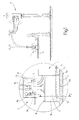
- Number 1 in Figure 1 indicates as a whole a magnetic gripping device, which is especially suitable for assembly on any type of pneumatic manipulator 2 to lift and move parts 3 of ferromagnetic material.
- gripping device 1 is designed to attach, on command and using the magnetic field produced by itself, to any part 3 of ferromagnetic material, so that part 3 is made temporarily integral with the free end of the articulated arm of pneumatic manipulator 2, and can be lifted and handled by an operator with the aid of pneumatic manipulator 2.
- gripping device 1 may obviously also be used for other purposes, such as clamping a part in position on a work surface.
- gripping device 1 comprises a magnetic assembly 4, which in turn comprises an outer anchoring surface 4a, which rests on part 3 to be engaged, an appropriately shaped outer magnetic core 5, and an inner magnetic core 6 mounted inside outer magnetic core 5 to rotate between two distinct operating positions corresponding to two distinct configurations of the magnetic circuit of magnetic assembly 4.
- outer anchoring surface 4a In the first circuit configuration, outer anchoring surface 4a is not crossed by the magnetic field lines, and is therefore prevented from attaching magnetically to the surface of part 3; whereas, in the second circuit configuration, outer anchoring surface 4a is crossed by the magnetic field lines, and can therefore attach magnetically to the surface of part 3 to lift the part.
- Gripping device 1 also comprises a torque-control actuating device 7, which, on command, rotates inner magnetic core 6 so as to set it selectively to either of said two operating positions; a position sensor 8 for determining when inner magnetic core 6 is in the operating position enabling magnetic assembly 4 to engage part 3, and possibly for determining when inner magnetic core 6 is in the operating position preventing magnetic assembly 4 from engaging part 3; and a control unit 9 for controlling actuating device 7 as commanded by the operator, for determining the coupling condition of magnetic assembly 4 and part 3 on the basis of signals from at least position sensor 8, and for possibly also supplying acoustic or visual coupling condition signals.
- a torque-control actuating device 7 which, on command, rotates inner magnetic core 6 so as to set it selectively to either of said two operating positions
- a position sensor 8 for determining when inner magnetic core 6 is in the operating position enabling magnetic assembly 4 to engage part 3, and possibly for determining when inner magnetic core 6 is in the operating position preventing magnetic assembly 4 from engaging part 3
- a control unit 9
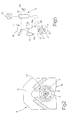
- inner magnetic core 6 is substantially cylindrical, and is mounted to rotate, about its longitudinal axis A, inside a through cavity 5a formed in and along the whole length of the body of outer magnetic core 5.
- Outer anchoring surface 4a of magnetic assembly 4 is defined by one of the outer lateral surfaces of outer magnetic core 5, and outer and inner magnetic cores 5 and 6 are made of ferromagnetic material and permanent magnets, so that inner magnetic core 6 can rotate, by a given angle and about axis A, between a first operating position - in which the magnetic poles of inner magnetic core 6 are positioned facing the opposite magnetic poles of outer magnetic core 5, so as to substantially eliminate the magnetic field produced by the latter at outer anchoring surface 4a - and a second operating position - in which the magnetic poles of inner magnetic core 6 are positioned facing the like magnetic poles of outer magnetic core 5, so as to amplify the magnetic field produced by the latter at outer anchoring surface 4a.
- magnetic assembly 4 also comprises two lateral cover plates 10 fixed to the two axial ends of outer magnetic core 5 to close the two openings of cavity 5a; and a shaft 11 for supporting inner magnetic core 6, and which extends, coaxially with axis A, along the whole length of magnetic assembly 4.
- Inner magnetic core 6 is fitted to shaft 11; and shaft 11 is mounted on the two lateral plates 10 so as to rotate about axis A, and has an end portion 11a projecting from one of lateral plates 10.
- magnetic assembly 4 will not be described further; any further information being obtainable in specialized literature, such as Patent WO-9965644.
- torque-control actuating device 7 is connected to end portion 11a of shaft 11, and, on command, rotates shaft 11 clockwise or anticlockwise by said angle to set inner magnetic core 6 to the first or second operating position, while at the same time controlling the value of the maximum twisting torque imparted to shaft 11 in doing so.
- actuating device 7 comprises a gear 12 fitted to end portion 11a of shaft 11; an open chain 13 wound partly about gear 12 to form a U in a plane perpendicular to axis A of shaft 11; and two pneumatic linear actuators 14 for drawing chain 13 back and forth to rotate gear 12 and shaft 11.
- Linear actuators 14 are fixed to the outer casing of magnetic assembly 4, on opposite sides of the center plane M containing axis A, and each has an output shaft 14a integral with a corresponding end of chain 13, so as to slide chain 13 by coordinated axial displacement of the two output shafts 14a.
- actuating device 7 comprises an electrically operated air distributor 15 for regulating pressurized air supply to pneumatic linear actuators 14 on command, so as to produce coordinated axial displacements of output shafts 14a of pneumatic linear actuators 14; and a pressure-regulating valve 16 located upstream from air distributor 15 to maintain a predetermined air supply pressure P o to air distributor 15, and therefore to pneumatic linear actuators 14.
- Pressure-regulating valve 16 may be controlled either electronically - so that supply pressure P o to air distributor 15 can be regulated directly by control unit 9 - or manually.
- position sensor 8 is defined by a microswitch located alongside output shaft 14a of one of pneumatic linear actuators 14 to indicate, by closure of an electric contact, when the relative output shaft 14a is so positioned as to set inner magnetic core 6 of magnetic assembly 4 to the second operating position.
- Position sensor 8 may obviously also comprise a second microswitch for indicating when the output shaft 14a is so positioned as to set inner magnetic core 6 of magnetic assembly 4 to the first operating position.
- control unit 9 comprises an electronic central control unit 17 for controlling air distributor 15 and, if possible, pressure-regulating valve 16; an operator control panel 18 by which to impart commands to electronic central control unit 17; and an acoustic and/or visual signaling device 19 for informing the operator when part 3 is engaged successfully by gripping device 1.
- the maximum twisting torque which must be imparted to shaft 11 to move inner magnetic core 6 from the first to the second operating position increases alongside an increase in the "gap" created between the surface of part 3 to be lifted and outer anchoring surface 4a of magnetic assembly 4; whereas the maximum load that can be lifted by magnetic assembly 4 decreases alongside an increase in the size of the "gap". Consequently, the greater the value of the twisting torque which must be imparted to shaft 11 to move inner magnetic core 6 from the first to the second operating position, i.e. for gripping device 1 to engage part 3, the smaller the maximum weight of part 3 that can be lifted with no risk of detachment.
- pressure-regulating valve 16 is electrically controlled and therefore controlled directly by electronic central control unit 17.
- electronic central control unit 17 controls pressure-regulating valve 16 so that the pressure P o of the air supply to air distributor 15 is sufficient to ensure the maximum twisting torque imparted to shaft 11 by pneumatic linear actuators 14 is no higher that that guaranteeing a part 3 of weight P max or less can be lifted safely.
- the maximum twisting torque that can be produced by actuating device 7, in fact, is a function of the pressure of the air supply to pneumatic linear actuators 14.
- gripping device 1 is ready for use by the operator, who, again working from control panel 18, switches inner magnetic core 6 from one operating position to the other so that gripping device 1 grips or releases part 3.
- electronic central control unit 17 controls air distributor 15 to feed pressurized air selectively to either one of pneumatic linear actuators 14, so as to rotate shaft 11 clockwise or anticlockwise by an angle equal to said angle , and so switch inner magnetic core 6 from the first to the second operating position or vice versa.
- torque-control actuating device 7 can only rotate inner magnetic core 6 from the first to the second operating position when the torque required to do so is less than or equal to the maximum torque it is capable of providing.
- actuating device 7 can only complete magnetic coupling of magnetic assembly 4 and part 3 if the magnetic coupling in question conforms with requirements, i.e. if the gap is small enough to ensure part 3 can be lifted in absolute safety, i.e. with no risk of accidental release.
- electronic central control unit 17 Given a maximum time for the switch to be completed, electronic central control unit 17, on the basis of signals from position sensor 8, is able to determine and inform the operator whether part 3 has been successfully engaged or released by magnetic assembly 4. In the example shown, electronic central control unit 17 indicates safe gripping of part 3, i.e. with no risk of accidental release of the part, by activating an indicator light 19 and/or buzzer on receiving from position sensor 8 a signal indicating output shaft 14a of the pneumatic linear actuator 14 has reached the required position.
- electronic central control unit 17 preferably, though not necessarily, also communicates with the electronic central control unit (not shown) controlling pneumatic manipulator 2, so as to disable operation of the manipulator until part 3 is engaged correctly and safely.
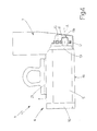
- torque-control actuating device 7 has no pressure-regulating valve 16, and comprises a load cell 20 for determining instant by instant the axial force transmitted by the two pneumatic linear actuators 14 to shaft 11 via chain 13 and gear 12, so as to work out the torque imparted to shaft 11 by actuating device 7.
- torque-control actuating device 7 is therefore always able to complete switching of the magnetic core from the first to the second operating position or vice versa, by there being no set limit to the maximum torque it can provide, other than, obviously, that imposed by the maximum pressure made available by the pneumatic circuit supplying it.
- Load cell 20 is obviously connected to electronic central control unit 17 to enable the control unit to determine, on the basis of the lifting characteristics of magnetic assembly 4, the maximum weight that can lifted each time, and to inform the operator of the relative value by means of an indicator (not shown).
- load cell 20 is interposed between chain 13 and the end of output shaft 14a of the pneumatic linear actuator 14 which pulls chain 13 to move inner magnetic core 6 from the first to the second operating position.
- position sensor 8 in addition to informing electronic central control unit 17 that rotation of inner magnetic core 6 has been completed, position sensor 8 also provides for determining which twisting torque value imparted by actuating device 7 to shaft 11 is to be used to determine the maximum load that can be lifted.
- electronic central control unit 17 takes as a reference the maximum torque immediately prior to the stop signal being received by position sensor 8.
- gripping device 1 may also comprise a second load cell 21 for determining the weight of part 3 engaged by magnetic assembly 4 when pneumatic manipulator 2 attempts to lift part 3. In which case, on determining the weight of part 3 is greater than the maximum weight permitted at that time, electronic central control unit 17 immediately disables pneumatic manipulator 2 and indicates an imminent operator hazard situation.
- load cell 21 is interposed between the outer casing of magnetic assembly 4 and the hook by which magnetic assembly 4 is suspended from the end of pneumatic manipulator 2.
- magnetic gripping device 1 the operator is no longer called upon to personally determine, with all the risks this entails, that gripping device 1 and part 3 are coupled firmly enough for part 3 to be lifted, thus greatly improving safety in the workplace.
- gripping device 1 Another advantage of gripping device 1 is that of no longer requiring strenuous effort on the part of the operator to operate the device manually.
- torque-control actuating device 7 is defined by a torque-control brushless electric motor or similar rotary electric actuating device, which is connected mechanically to shaft 11 of magnetic assembly 4 to rotate shaft 11, on command, about axis A, or keep shaft 11 stationary in a given position, while exerting a predetermined torque.
- the position of shaft 11 is determined indirectly by the "encoder" this type of motor is normally equipped with, and the twisting torque exerted by actuating device 7 can be determined or limited indirectly by controlling or respectively limiting the electric current drawn by the electric motor.
Landscapes
- Engineering & Computer Science (AREA)
- Mechanical Engineering (AREA)
- Robotics (AREA)
- Manipulator (AREA)
- Electromagnets (AREA)
Applications Claiming Priority (2)
| Application Number | Priority Date | Filing Date | Title |
|---|---|---|---|
| IT2001BO000305A ITBO20010305A1 (it) | 2001-05-17 | 2001-05-17 | Dispositivo di presa a funzionamento magnetico di tipo servocomandato |
| ITBO20010305 | 2001-05-17 |
Publications (2)
| Publication Number | Publication Date |
|---|---|
| EP1258324A2 true EP1258324A2 (fr) | 2002-11-20 |
| EP1258324A3 EP1258324A3 (fr) | 2003-04-02 |
Family
ID=11439350
Family Applications (1)
| Application Number | Title | Priority Date | Filing Date |
|---|---|---|---|
| EP02010928A Withdrawn EP1258324A3 (fr) | 2001-05-17 | 2002-05-16 | Dispositif de préhension magnétique asservi |
Country Status (3)
| Country | Link |
|---|---|
| US (1) | US6663154B2 (fr) |
| EP (1) | EP1258324A3 (fr) |
| IT (1) | ITBO20010305A1 (fr) |
Cited By (28)
| Publication number | Priority date | Publication date | Assignee | Title |
|---|---|---|---|---|
| WO2004067433A1 (fr) * | 2003-01-29 | 2004-08-12 | James Neill Holdings Limited | Elements d'ancrage magnetiques |
| FR2907440A1 (fr) * | 2006-10-19 | 2008-04-25 | Ingenitec Sarl | Manupulateur de charges a colonne telescopique |
| ITUD20090054A1 (it) * | 2009-03-09 | 2010-09-10 | Scaglia Indeva S P A | Dispositivo di manipolazione e relativo procedimento |
| WO2012149363A3 (fr) * | 2011-04-29 | 2013-04-18 | Raytheon Company | Organe effecteur magnétique à puissance variable pour systèmes de levage |
| ITBS20120085A1 (it) * | 2012-05-18 | 2013-11-19 | Ense Srl | Attuatore particolarmente per sollevatori a magneti permanenti |
| US8942846B2 (en) | 2011-04-29 | 2015-01-27 | Raytheon Company | System and method for controlling a teleoperated robotic agile lift system |
| US8977388B2 (en) | 2011-04-29 | 2015-03-10 | Sarcos Lc | Platform perturbation compensation |
| US9314921B2 (en) | 2011-03-17 | 2016-04-19 | Sarcos Lc | Robotic lift device with human interface operation |
| US9789603B2 (en) | 2011-04-29 | 2017-10-17 | Sarcos Lc | Teleoperated robotic system |
| WO2018192729A1 (fr) * | 2017-04-20 | 2018-10-25 | Wisco Lasertechnik Gmbh | Cadre à éléments de préhension magnétiques |
| US10766133B2 (en) | 2014-05-06 | 2020-09-08 | Sarcos Lc | Legged robotic device utilizing modifiable linkage mechanism |
| US10765537B2 (en) | 2016-11-11 | 2020-09-08 | Sarcos Corp. | Tunable actuator joint modules having energy recovering quasi-passive elastic actuators for use within a robotic system |
| US10780588B2 (en) | 2012-05-14 | 2020-09-22 | Sarcos Lc | End effector for a robotic arm |
| US10821614B2 (en) | 2016-11-11 | 2020-11-03 | Sarcos Corp. | Clutched joint modules having a quasi-passive elastic actuator for a robotic assembly |
| US10828767B2 (en) | 2016-11-11 | 2020-11-10 | Sarcos Corp. | Tunable actuator joint modules having energy recovering quasi-passive elastic actuators with internal valve arrangements |
| US10843330B2 (en) | 2017-12-07 | 2020-11-24 | Sarcos Corp. | Resistance-based joint constraint for a master robotic system |
| US10906191B2 (en) | 2018-12-31 | 2021-02-02 | Sarcos Corp. | Hybrid robotic end effector |
| US10919161B2 (en) | 2016-11-11 | 2021-02-16 | Sarcos Corp. | Clutched joint modules for a robotic system |
| US11241801B2 (en) | 2018-12-31 | 2022-02-08 | Sarcos Corp. | Robotic end effector with dorsally supported actuation mechanism |
| US11331809B2 (en) | 2017-12-18 | 2022-05-17 | Sarcos Corp. | Dynamically controlled robotic stiffening element |
| US11351675B2 (en) | 2018-12-31 | 2022-06-07 | Sarcos Corp. | Robotic end-effector having dynamic stiffening elements for conforming object interaction |
| US11717956B1 (en) | 2022-08-29 | 2023-08-08 | Sarcos Corp. | Robotic joint system with integrated safety |
| US11794345B2 (en) | 2020-12-31 | 2023-10-24 | Sarcos Corp. | Unified robotic vehicle systems and methods of control |
| US11826907B1 (en) | 2022-08-17 | 2023-11-28 | Sarcos Corp. | Robotic joint system with length adapter |
| US11833676B2 (en) | 2020-12-07 | 2023-12-05 | Sarcos Corp. | Combining sensor output data to prevent unsafe operation of an exoskeleton |
| US11897132B1 (en) | 2022-11-17 | 2024-02-13 | Sarcos Corp. | Systems and methods for redundant network communication in a robot |
| US11924023B1 (en) | 2022-11-17 | 2024-03-05 | Sarcos Corp. | Systems and methods for redundant network communication in a robot |
| US12172298B2 (en) | 2022-11-04 | 2024-12-24 | Sarcos Corp. | Robotic end-effector having dynamic stiffening elements with resilient spacers for conforming object interaction |
Families Citing this family (18)
| Publication number | Priority date | Publication date | Assignee | Title |
|---|---|---|---|---|
| KR20030086562A (ko) * | 2003-10-24 | 2003-11-10 | 예해금 | 자력흡착기의 흡착자력 스위치장치 |
| US8183965B2 (en) | 2010-04-09 | 2012-05-22 | Creative Engineering Solutions, Inc. | Switchable core element-based permanent magnet apparatus |
| US8985936B2 (en) | 2012-09-11 | 2015-03-24 | Nidec Minster Corporation | Method and apparatus for orienting a lamination |
| US10406676B2 (en) | 2014-05-06 | 2019-09-10 | Sarcos Lc | Energy recovering legged robotic device |
| EP3002372B1 (fr) * | 2014-10-02 | 2016-09-14 | Delmag GmbH & Co. KG | Jumelle à emboîtement |
| CN104908027B (zh) * | 2015-06-18 | 2017-03-01 | 南京理工大学 | 轮毂毛坯上下料气动平衡助力机械手 |
| GB2560000B (en) | 2017-02-24 | 2021-06-09 | Roke Manor Res Limited | A coupling mechanism for light vehicles |
| US10903030B2 (en) | 2017-04-27 | 2021-01-26 | Magswitch Technology Worldwide Pty Ltd. | Variable field magnetic couplers and methods for engaging a ferromagnetic workpiece |
| ES3025191T3 (en) | 2017-04-27 | 2025-06-06 | Magswitch Tech Worldwide Pty Ltd | Magnetic coupling device with at least one of a sensor arrangement and a degauss capability |
| US20250065460A1 (en) * | 2017-04-27 | 2025-02-27 | Magswitch Technology, Inc. | Magnetic coupling device with at least one of a sensor arrangement and a degauss capability |
| CN111093891B (zh) | 2017-04-27 | 2022-08-02 | 磁转换技术全球私人有限公司 | 具有至少一个传感器布置和消磁能力的磁耦合装置 |
| WO2018227140A1 (fr) | 2017-06-08 | 2018-12-13 | Magswitch Technology Worldwide Pty Ltd. | Dispositif à aimant permanent commutable par électro-aimant |
| CN108557470B (zh) * | 2018-01-16 | 2020-07-28 | 深圳市华星光电技术有限公司 | 显示面板取放装置 |
| IT202000011206A1 (it) * | 2020-05-15 | 2021-11-15 | Famatec S R L | Metodo di costruzione dell'attrezzatura prensile di un apparecchio di sollevamento ed apparecchio di sollevamento provvisto di tale attrezzatura prensile |
| EP3925923B1 (fr) | 2020-06-17 | 2023-04-19 | Famatec S.r.l. | Équipement de préhension pour appareils de levage et appareils de levage munis d'un tel équipement de préhension |
| KR102284603B1 (ko) * | 2021-03-29 | 2021-08-02 | 주식회사 상영마그네트 | 마그네틱 리프트 장치 |
| WO2022261520A1 (fr) | 2021-06-11 | 2022-12-15 | Magswitch Technology, Inc. | Organe effecteur ou dispositif de fixation réglable |
| EP4721419A1 (fr) * | 2023-06-02 | 2026-04-08 | Brane Audio, LLC | Haut-parleurs et leurs procédés d'utilisation |
Family Cites Families (13)
| Publication number | Priority date | Publication date | Assignee | Title |
|---|---|---|---|---|
| US2471067A (en) * | 1944-11-06 | 1949-05-24 | Tropical Plantations Ltd | Magnetic work holder |
| JPS5434013A (en) * | 1977-08-20 | 1979-03-13 | Shinano Tokki Kk | Electromagnetic rotating apparatus |
| IT7823323V0 (it) * | 1978-11-17 | 1978-11-17 | Cardone Tecnomagnetica | Sollevatore magnetico a comando manuale. |
| JPS5578505A (en) * | 1978-12-08 | 1980-06-13 | Kanetsuu Kogyo Kk | Attraction type magnetic device |
| BR8702929A (pt) * | 1987-05-22 | 1988-12-20 | Josef David Baumann | Dispositivo permanente magnetico de retencao para movimentacao fixacao ou transporte de pecas ou cargas ferromagneticas com comutacao eletronica do fluxo magnetico para desligamento da carga transportada |
| SU1570894A1 (ru) * | 1988-03-28 | 1990-06-15 | Новочеркасский Политехнический Институт Им.Серго Орджоникидзе | Схват |
| US4921292A (en) * | 1988-09-23 | 1990-05-01 | The United States Of America As Represented By The Administrator Of The National Aeronautics And Space Administration | Magnetic attachment mechanism |
| FR2675299B1 (fr) * | 1991-04-10 | 1994-09-16 | Braillon Cie | Porteur magnetique a aimants permanents. |
| KR950006689Y1 (ko) * | 1992-12-15 | 1995-08-18 | 정형 | 자력 흡착기 |
| IT1301710B1 (it) * | 1998-06-15 | 2000-07-07 | Tecnomagnete Spa | Ancoratore magnetico a comando manuale. |
| KR100288245B1 (ko) * | 1998-07-24 | 2001-05-02 | 정형 | 자력흡착기의 흡착자력 자동개폐장치 |
| AUPQ446699A0 (en) * | 1999-12-06 | 2000-01-06 | Kocijan, Franz | Switchable (variable) permanent magnet device |
| US6331810B1 (en) * | 2000-09-01 | 2001-12-18 | Hyung Jung | Magnetic lifting apparatus |
-
2001
- 2001-05-17 IT IT2001BO000305A patent/ITBO20010305A1/it unknown
-
2002
- 2002-05-16 EP EP02010928A patent/EP1258324A3/fr not_active Withdrawn
- 2002-05-17 US US10/150,651 patent/US6663154B2/en not_active Expired - Fee Related
Cited By (38)
| Publication number | Priority date | Publication date | Assignee | Title |
|---|---|---|---|---|
| WO2004067433A1 (fr) * | 2003-01-29 | 2004-08-12 | James Neill Holdings Limited | Elements d'ancrage magnetiques |
| FR2907440A1 (fr) * | 2006-10-19 | 2008-04-25 | Ingenitec Sarl | Manupulateur de charges a colonne telescopique |
| ITUD20090054A1 (it) * | 2009-03-09 | 2010-09-10 | Scaglia Indeva S P A | Dispositivo di manipolazione e relativo procedimento |
| US9314921B2 (en) | 2011-03-17 | 2016-04-19 | Sarcos Lc | Robotic lift device with human interface operation |
| US11745331B2 (en) | 2011-04-29 | 2023-09-05 | Sarcos, Lc | Teleoperated robotic system with payload stabilization |
| US11738446B2 (en) | 2011-04-29 | 2023-08-29 | Sarcos, Lc | Teleoperated robotic system with impact responsive force feedback |
| US8942846B2 (en) | 2011-04-29 | 2015-01-27 | Raytheon Company | System and method for controlling a teleoperated robotic agile lift system |
| US8977388B2 (en) | 2011-04-29 | 2015-03-10 | Sarcos Lc | Platform perturbation compensation |
| US8977398B2 (en) | 2011-04-29 | 2015-03-10 | Sarcos Lc | Multi-degree of freedom torso support for a robotic agile lift system |
| US9533411B2 (en) | 2011-04-29 | 2017-01-03 | Sarcos Lc | System and method for controlling a teleoperated robotic agile lift system |
| US9789603B2 (en) | 2011-04-29 | 2017-10-17 | Sarcos Lc | Teleoperated robotic system |
| US8892258B2 (en) | 2011-04-29 | 2014-11-18 | Raytheon Company | Variable strength magnetic end effector for lift systems |
| WO2012149363A3 (fr) * | 2011-04-29 | 2013-04-18 | Raytheon Company | Organe effecteur magnétique à puissance variable pour systèmes de levage |
| US10780588B2 (en) | 2012-05-14 | 2020-09-22 | Sarcos Lc | End effector for a robotic arm |
| ITBS20120085A1 (it) * | 2012-05-18 | 2013-11-19 | Ense Srl | Attuatore particolarmente per sollevatori a magneti permanenti |
| US10766133B2 (en) | 2014-05-06 | 2020-09-08 | Sarcos Lc | Legged robotic device utilizing modifiable linkage mechanism |
| US11772283B2 (en) | 2016-11-11 | 2023-10-03 | Sarcos Corp. | Clutched joint modules having a quasi-passive elastic actuator for a robotic assembly |
| US10821614B2 (en) | 2016-11-11 | 2020-11-03 | Sarcos Corp. | Clutched joint modules having a quasi-passive elastic actuator for a robotic assembly |
| US11981027B2 (en) | 2016-11-11 | 2024-05-14 | Sarcos Corp. | Tunable actuator joint modules having energy recovering quasi-passive elastic actuators with internal valve arrangements |
| US10919161B2 (en) | 2016-11-11 | 2021-02-16 | Sarcos Corp. | Clutched joint modules for a robotic system |
| US11926044B2 (en) | 2016-11-11 | 2024-03-12 | Sarcos Corp. | Clutched joint modules having a quasi-passive elastic actuator for a robotic assembly |
| US10828767B2 (en) | 2016-11-11 | 2020-11-10 | Sarcos Corp. | Tunable actuator joint modules having energy recovering quasi-passive elastic actuators with internal valve arrangements |
| US11759944B2 (en) | 2016-11-11 | 2023-09-19 | Sarcos Corp. | Tunable actuator joint modules having energy recovering quasi- passive elastic actuators with internal valve arrangements |
| US10765537B2 (en) | 2016-11-11 | 2020-09-08 | Sarcos Corp. | Tunable actuator joint modules having energy recovering quasi-passive elastic actuators for use within a robotic system |
| WO2018192729A1 (fr) * | 2017-04-20 | 2018-10-25 | Wisco Lasertechnik Gmbh | Cadre à éléments de préhension magnétiques |
| US10843330B2 (en) | 2017-12-07 | 2020-11-24 | Sarcos Corp. | Resistance-based joint constraint for a master robotic system |
| US11331809B2 (en) | 2017-12-18 | 2022-05-17 | Sarcos Corp. | Dynamically controlled robotic stiffening element |
| US11679511B2 (en) | 2018-12-31 | 2023-06-20 | Sarcos Corp. | Robotic end effector with dorsally supported actuation mechanism |
| US11351675B2 (en) | 2018-12-31 | 2022-06-07 | Sarcos Corp. | Robotic end-effector having dynamic stiffening elements for conforming object interaction |
| US11241801B2 (en) | 2018-12-31 | 2022-02-08 | Sarcos Corp. | Robotic end effector with dorsally supported actuation mechanism |
| US10906191B2 (en) | 2018-12-31 | 2021-02-02 | Sarcos Corp. | Hybrid robotic end effector |
| US11833676B2 (en) | 2020-12-07 | 2023-12-05 | Sarcos Corp. | Combining sensor output data to prevent unsafe operation of an exoskeleton |
| US11794345B2 (en) | 2020-12-31 | 2023-10-24 | Sarcos Corp. | Unified robotic vehicle systems and methods of control |
| US11826907B1 (en) | 2022-08-17 | 2023-11-28 | Sarcos Corp. | Robotic joint system with length adapter |
| US11717956B1 (en) | 2022-08-29 | 2023-08-08 | Sarcos Corp. | Robotic joint system with integrated safety |
| US12172298B2 (en) | 2022-11-04 | 2024-12-24 | Sarcos Corp. | Robotic end-effector having dynamic stiffening elements with resilient spacers for conforming object interaction |
| US11897132B1 (en) | 2022-11-17 | 2024-02-13 | Sarcos Corp. | Systems and methods for redundant network communication in a robot |
| US11924023B1 (en) | 2022-11-17 | 2024-03-05 | Sarcos Corp. | Systems and methods for redundant network communication in a robot |
Also Published As
| Publication number | Publication date |
|---|---|
| US6663154B2 (en) | 2003-12-16 |
| ITBO20010305A0 (it) | 2001-05-17 |
| ITBO20010305A1 (it) | 2002-11-17 |
| EP1258324A3 (fr) | 2003-04-02 |
| US20020190532A1 (en) | 2002-12-19 |
Similar Documents
| Publication | Publication Date | Title |
|---|---|---|
| US6663154B2 (en) | Servocontrolled magnetic gripping device | |
| US7222839B2 (en) | Cable slack and guide monitoring apparatus and method for a lift device | |
| JP2610117B2 (ja) | 荷物を掴む方法 | |
| US12103180B2 (en) | Robotic gripper | |
| EP1190980A2 (fr) | Procédé pour contrôler le fonctionnement d' un frein de grue | |
| US4236864A (en) | Safety control system for the boom of a crane | |
| US6370970B1 (en) | Cargo handling machine including force control | |
| EP1183206B1 (fr) | Amplificateur de force humaine pour levage de charges avec dispositif anti-mou pour l'elingue | |
| DK159874B (da) | Godshejsevaerk med et manoevreringsorgan mellem lastbaereorganet og et drivorgan | |
| CN101513981A (zh) | 应对起重机重物失控下落的制动方案 | |
| US20020144970A1 (en) | Pendant controller for overhead lifting systems | |
| US10913158B2 (en) | Robotic system | |
| EP0308163A2 (fr) | Dispositif pour dérouler | |
| CN203465087U (zh) | 输配电开关柜操动机构的寿命试验系统 | |
| GB2299383A (en) | A braking assembly | |
| WO1996022175A3 (fr) | Dispositif de securite pour outils a main a moteur electrique, notamment scies circulaires et scies alternatives | |
| KR100605667B1 (ko) | 로드셀 컨트롤식 무중력 전기모터 구동식 리프터 | |
| JP3232320U (ja) | 搬送補助装置のワーク保持手段および搬送補助装置 | |
| CN203066899U (zh) | 钢丝绳松紧限位装置 | |
| CN220563399U (zh) | 一种吨桶自动开关盖机械手 | |
| JPH0636079Y2 (ja) | プッシュプル付き荷役車両のシートグリッパ作動装置 | |
| JP2529513Y2 (ja) | クレーンの巻胴制御装置 | |
| CA2487979C (fr) | Amplificateur de force humaine pour levage de charges avec dispositif anti-mou pour l'elingue | |
| KR970007460B1 (ko) | 원격조정이 가능한 유압윈치 | |
| JP2017087341A (ja) | ロボットシステム及びロボットの教示装置 |
Legal Events
| Date | Code | Title | Description |
|---|---|---|---|
| PUAI | Public reference made under article 153(3) epc to a published international application that has entered the european phase |
Free format text: ORIGINAL CODE: 0009012 |
|
| AK | Designated contracting states |
Kind code of ref document: A2 Designated state(s): AT BE CH CY DE DK ES FI FR GB GR IE IT LI LU MC NL PT SE TR |
|
| AX | Request for extension of the european patent |
Free format text: AL;LT;LV;MK;RO;SI |
|
| PUAL | Search report despatched |
Free format text: ORIGINAL CODE: 0009013 |
|
| AK | Designated contracting states |
Kind code of ref document: A3 Designated state(s): AT BE CH CY DE DK ES FI FR GB GR IE IT LI LU MC NL PT SE TR Designated state(s): AT BE CH CY DE DK ES FI FR GB GR IE IT LI LU MC NL PT SE TR |
|
| AX | Request for extension of the european patent |
Extension state: AL LT LV MK RO SI |
|
| RIC1 | Information provided on ipc code assigned before grant |
Ipc: 7H 01F 7/02 B Ipc: 7B 66C 1/04 B Ipc: 7B 25J 15/06 A |
|
| 17P | Request for examination filed |
Effective date: 20030612 |
|
| AKX | Designation fees paid |
Designated state(s): AT BE CH CY DE DK ES FI FR GB GR IE IT LI LU MC NL PT SE TR |
|
| RAP1 | Party data changed (applicant data changed or rights of an application transferred) |
Owner name: FAMATEC S.P.A. |
|
| 17Q | First examination report despatched |
Effective date: 20101103 |
|
| STAA | Information on the status of an ep patent application or granted ep patent |
Free format text: STATUS: THE APPLICATION IS DEEMED TO BE WITHDRAWN |
|
| 18D | Application deemed to be withdrawn |
Effective date: 20151201 |