EP1258355A1 - Tete a jets d'encre, procede de production de tete a jets d'encre, et imprimante - Google Patents
Tete a jets d'encre, procede de production de tete a jets d'encre, et imprimante Download PDFInfo
- Publication number
- EP1258355A1 EP1258355A1 EP99959763A EP99959763A EP1258355A1 EP 1258355 A1 EP1258355 A1 EP 1258355A1 EP 99959763 A EP99959763 A EP 99959763A EP 99959763 A EP99959763 A EP 99959763A EP 1258355 A1 EP1258355 A1 EP 1258355A1
- Authority
- EP
- European Patent Office
- Prior art keywords
- ink
- main body
- head main
- ink jet
- jet head
- Prior art date
- Legal status (The legal status is an assumption and is not a legal conclusion. Google has not performed a legal analysis and makes no representation as to the accuracy of the status listed.)
- Granted
Links
Images










Classifications
-
- B—PERFORMING OPERATIONS; TRANSPORTING
- B41—PRINTING; LINING MACHINES; TYPEWRITERS; STAMPS
- B41J—TYPEWRITERS; SELECTIVE PRINTING MECHANISMS, i.e. MECHANISMS PRINTING OTHERWISE THAN FROM A FORME; CORRECTION OF TYPOGRAPHICAL ERRORS
- B41J2/00—Typewriters or selective printing mechanisms characterised by the printing or marking process for which they are designed
- B41J2/005—Typewriters or selective printing mechanisms characterised by the printing or marking process for which they are designed characterised by bringing liquid or particles selectively into contact with a printing material
- B41J2/01—Ink jet
- B41J2/17—Ink jet characterised by ink handling
- B41J2/175—Ink supply systems ; Circuit parts therefor
-
- B—PERFORMING OPERATIONS; TRANSPORTING
- B41—PRINTING; LINING MACHINES; TYPEWRITERS; STAMPS
- B41J—TYPEWRITERS; SELECTIVE PRINTING MECHANISMS, i.e. MECHANISMS PRINTING OTHERWISE THAN FROM A FORME; CORRECTION OF TYPOGRAPHICAL ERRORS
- B41J2/00—Typewriters or selective printing mechanisms characterised by the printing or marking process for which they are designed
- B41J2/005—Typewriters or selective printing mechanisms characterised by the printing or marking process for which they are designed characterised by bringing liquid or particles selectively into contact with a printing material
- B41J2/01—Ink jet
- B41J2/135—Nozzles
- B41J2/16—Production of nozzles
- B41J2/1621—Manufacturing processes
- B41J2/1623—Manufacturing processes bonding and adhesion
-
- B—PERFORMING OPERATIONS; TRANSPORTING
- B41—PRINTING; LINING MACHINES; TYPEWRITERS; STAMPS
- B41J—TYPEWRITERS; SELECTIVE PRINTING MECHANISMS, i.e. MECHANISMS PRINTING OTHERWISE THAN FROM A FORME; CORRECTION OF TYPOGRAPHICAL ERRORS
- B41J2/00—Typewriters or selective printing mechanisms characterised by the printing or marking process for which they are designed
- B41J2/005—Typewriters or selective printing mechanisms characterised by the printing or marking process for which they are designed characterised by bringing liquid or particles selectively into contact with a printing material
- B41J2/01—Ink jet
- B41J2/135—Nozzles
- B41J2/14—Structure thereof only for on-demand ink jet heads
- B41J2/14201—Structure of print heads with piezoelectric elements
- B41J2/14233—Structure of print heads with piezoelectric elements of film type, deformed by bending and disposed on a diaphragm
-
- B—PERFORMING OPERATIONS; TRANSPORTING
- B41—PRINTING; LINING MACHINES; TYPEWRITERS; STAMPS
- B41J—TYPEWRITERS; SELECTIVE PRINTING MECHANISMS, i.e. MECHANISMS PRINTING OTHERWISE THAN FROM A FORME; CORRECTION OF TYPOGRAPHICAL ERRORS
- B41J2/00—Typewriters or selective printing mechanisms characterised by the printing or marking process for which they are designed
- B41J2/005—Typewriters or selective printing mechanisms characterised by the printing or marking process for which they are designed characterised by bringing liquid or particles selectively into contact with a printing material
- B41J2/01—Ink jet
- B41J2/135—Nozzles
- B41J2/16—Production of nozzles
- B41J2/1607—Production of print heads with piezoelectric elements
- B41J2/161—Production of print heads with piezoelectric elements of film type, deformed by bending and disposed on a diaphragm
-
- B—PERFORMING OPERATIONS; TRANSPORTING
- B41—PRINTING; LINING MACHINES; TYPEWRITERS; STAMPS
- B41J—TYPEWRITERS; SELECTIVE PRINTING MECHANISMS, i.e. MECHANISMS PRINTING OTHERWISE THAN FROM A FORME; CORRECTION OF TYPOGRAPHICAL ERRORS
- B41J2/00—Typewriters or selective printing mechanisms characterised by the printing or marking process for which they are designed
- B41J2/005—Typewriters or selective printing mechanisms characterised by the printing or marking process for which they are designed characterised by bringing liquid or particles selectively into contact with a printing material
- B41J2/01—Ink jet
- B41J2/135—Nozzles
- B41J2/16—Production of nozzles
- B41J2/1621—Manufacturing processes
- B41J2/1626—Manufacturing processes etching
-
- B—PERFORMING OPERATIONS; TRANSPORTING
- B41—PRINTING; LINING MACHINES; TYPEWRITERS; STAMPS
- B41J—TYPEWRITERS; SELECTIVE PRINTING MECHANISMS, i.e. MECHANISMS PRINTING OTHERWISE THAN FROM A FORME; CORRECTION OF TYPOGRAPHICAL ERRORS
- B41J2/00—Typewriters or selective printing mechanisms characterised by the printing or marking process for which they are designed
- B41J2/005—Typewriters or selective printing mechanisms characterised by the printing or marking process for which they are designed characterised by bringing liquid or particles selectively into contact with a printing material
- B41J2/01—Ink jet
- B41J2/135—Nozzles
- B41J2/16—Production of nozzles
- B41J2/1621—Manufacturing processes
- B41J2/1626—Manufacturing processes etching
- B41J2/1629—Manufacturing processes etching wet etching
-
- B—PERFORMING OPERATIONS; TRANSPORTING
- B41—PRINTING; LINING MACHINES; TYPEWRITERS; STAMPS
- B41J—TYPEWRITERS; SELECTIVE PRINTING MECHANISMS, i.e. MECHANISMS PRINTING OTHERWISE THAN FROM A FORME; CORRECTION OF TYPOGRAPHICAL ERRORS
- B41J2/00—Typewriters or selective printing mechanisms characterised by the printing or marking process for which they are designed
- B41J2/005—Typewriters or selective printing mechanisms characterised by the printing or marking process for which they are designed characterised by bringing liquid or particles selectively into contact with a printing material
- B41J2/01—Ink jet
- B41J2/135—Nozzles
- B41J2/16—Production of nozzles
- B41J2/1621—Manufacturing processes
- B41J2/1631—Manufacturing processes photolithography
-
- B—PERFORMING OPERATIONS; TRANSPORTING
- B41—PRINTING; LINING MACHINES; TYPEWRITERS; STAMPS
- B41J—TYPEWRITERS; SELECTIVE PRINTING MECHANISMS, i.e. MECHANISMS PRINTING OTHERWISE THAN FROM A FORME; CORRECTION OF TYPOGRAPHICAL ERRORS
- B41J2/00—Typewriters or selective printing mechanisms characterised by the printing or marking process for which they are designed
- B41J2/005—Typewriters or selective printing mechanisms characterised by the printing or marking process for which they are designed characterised by bringing liquid or particles selectively into contact with a printing material
- B41J2/01—Ink jet
- B41J2/135—Nozzles
- B41J2/16—Production of nozzles
- B41J2/1621—Manufacturing processes
- B41J2/1632—Manufacturing processes machining
-
- B—PERFORMING OPERATIONS; TRANSPORTING
- B41—PRINTING; LINING MACHINES; TYPEWRITERS; STAMPS
- B41J—TYPEWRITERS; SELECTIVE PRINTING MECHANISMS, i.e. MECHANISMS PRINTING OTHERWISE THAN FROM A FORME; CORRECTION OF TYPOGRAPHICAL ERRORS
- B41J2/00—Typewriters or selective printing mechanisms characterised by the printing or marking process for which they are designed
- B41J2/005—Typewriters or selective printing mechanisms characterised by the printing or marking process for which they are designed characterised by bringing liquid or particles selectively into contact with a printing material
- B41J2/01—Ink jet
- B41J2/135—Nozzles
- B41J2/16—Production of nozzles
- B41J2/1621—Manufacturing processes
- B41J2/164—Manufacturing processes thin film formation
- B41J2/1643—Manufacturing processes thin film formation thin film formation by plating
-
- B—PERFORMING OPERATIONS; TRANSPORTING
- B41—PRINTING; LINING MACHINES; TYPEWRITERS; STAMPS
- B41J—TYPEWRITERS; SELECTIVE PRINTING MECHANISMS, i.e. MECHANISMS PRINTING OTHERWISE THAN FROM A FORME; CORRECTION OF TYPOGRAPHICAL ERRORS
- B41J2/00—Typewriters or selective printing mechanisms characterised by the printing or marking process for which they are designed
- B41J2/005—Typewriters or selective printing mechanisms characterised by the printing or marking process for which they are designed characterised by bringing liquid or particles selectively into contact with a printing material
- B41J2/01—Ink jet
- B41J2/135—Nozzles
- B41J2/16—Production of nozzles
- B41J2/1621—Manufacturing processes
- B41J2/164—Manufacturing processes thin film formation
- B41J2/1646—Manufacturing processes thin film formation thin film formation by sputtering
-
- B—PERFORMING OPERATIONS; TRANSPORTING
- B41—PRINTING; LINING MACHINES; TYPEWRITERS; STAMPS
- B41J—TYPEWRITERS; SELECTIVE PRINTING MECHANISMS, i.e. MECHANISMS PRINTING OTHERWISE THAN FROM A FORME; CORRECTION OF TYPOGRAPHICAL ERRORS
- B41J2/00—Typewriters or selective printing mechanisms characterised by the printing or marking process for which they are designed
- B41J2/005—Typewriters or selective printing mechanisms characterised by the printing or marking process for which they are designed characterised by bringing liquid or particles selectively into contact with a printing material
- B41J2/01—Ink jet
- B41J2/17—Ink jet characterised by ink handling
- B41J2/175—Ink supply systems ; Circuit parts therefor
- B41J2/17503—Ink cartridges
- B41J2/17513—Inner structure
-
- B—PERFORMING OPERATIONS; TRANSPORTING
- B41—PRINTING; LINING MACHINES; TYPEWRITERS; STAMPS
- B41J—TYPEWRITERS; SELECTIVE PRINTING MECHANISMS, i.e. MECHANISMS PRINTING OTHERWISE THAN FROM A FORME; CORRECTION OF TYPOGRAPHICAL ERRORS
- B41J2/00—Typewriters or selective printing mechanisms characterised by the printing or marking process for which they are designed
- B41J2/005—Typewriters or selective printing mechanisms characterised by the printing or marking process for which they are designed characterised by bringing liquid or particles selectively into contact with a printing material
- B41J2/01—Ink jet
- B41J2/135—Nozzles
- B41J2/14—Structure thereof only for on-demand ink jet heads
- B41J2/14201—Structure of print heads with piezoelectric elements
- B41J2/14233—Structure of print heads with piezoelectric elements of film type, deformed by bending and disposed on a diaphragm
- B41J2002/1425—Embedded thin film piezoelectric element
-
- B—PERFORMING OPERATIONS; TRANSPORTING
- B41—PRINTING; LINING MACHINES; TYPEWRITERS; STAMPS
- B41J—TYPEWRITERS; SELECTIVE PRINTING MECHANISMS, i.e. MECHANISMS PRINTING OTHERWISE THAN FROM A FORME; CORRECTION OF TYPOGRAPHICAL ERRORS
- B41J2/00—Typewriters or selective printing mechanisms characterised by the printing or marking process for which they are designed
- B41J2/005—Typewriters or selective printing mechanisms characterised by the printing or marking process for which they are designed characterised by bringing liquid or particles selectively into contact with a printing material
- B41J2/01—Ink jet
- B41J2/135—Nozzles
- B41J2/14—Structure thereof only for on-demand ink jet heads
- B41J2002/14403—Structure thereof only for on-demand ink jet heads including a filter
-
- B—PERFORMING OPERATIONS; TRANSPORTING
- B41—PRINTING; LINING MACHINES; TYPEWRITERS; STAMPS
- B41J—TYPEWRITERS; SELECTIVE PRINTING MECHANISMS, i.e. MECHANISMS PRINTING OTHERWISE THAN FROM A FORME; CORRECTION OF TYPOGRAPHICAL ERRORS
- B41J2/00—Typewriters or selective printing mechanisms characterised by the printing or marking process for which they are designed
- B41J2/005—Typewriters or selective printing mechanisms characterised by the printing or marking process for which they are designed characterised by bringing liquid or particles selectively into contact with a printing material
- B41J2/01—Ink jet
- B41J2/135—Nozzles
- B41J2/14—Structure thereof only for on-demand ink jet heads
- B41J2002/14419—Manifold
-
- B—PERFORMING OPERATIONS; TRANSPORTING
- B41—PRINTING; LINING MACHINES; TYPEWRITERS; STAMPS
- B41J—TYPEWRITERS; SELECTIVE PRINTING MECHANISMS, i.e. MECHANISMS PRINTING OTHERWISE THAN FROM A FORME; CORRECTION OF TYPOGRAPHICAL ERRORS
- B41J2/00—Typewriters or selective printing mechanisms characterised by the printing or marking process for which they are designed
- B41J2/005—Typewriters or selective printing mechanisms characterised by the printing or marking process for which they are designed characterised by bringing liquid or particles selectively into contact with a printing material
- B41J2/01—Ink jet
- B41J2/135—Nozzles
- B41J2/14—Structure thereof only for on-demand ink jet heads
- B41J2002/14467—Multiple feed channels per ink chamber
-
- B—PERFORMING OPERATIONS; TRANSPORTING
- B41—PRINTING; LINING MACHINES; TYPEWRITERS; STAMPS
- B41J—TYPEWRITERS; SELECTIVE PRINTING MECHANISMS, i.e. MECHANISMS PRINTING OTHERWISE THAN FROM A FORME; CORRECTION OF TYPOGRAPHICAL ERRORS
- B41J2/00—Typewriters or selective printing mechanisms characterised by the printing or marking process for which they are designed
- B41J2/005—Typewriters or selective printing mechanisms characterised by the printing or marking process for which they are designed characterised by bringing liquid or particles selectively into contact with a printing material
- B41J2/01—Ink jet
- B41J2/135—Nozzles
- B41J2/14—Structure thereof only for on-demand ink jet heads
- B41J2002/14491—Electrical connection
-
- Y—GENERAL TAGGING OF NEW TECHNOLOGICAL DEVELOPMENTS; GENERAL TAGGING OF CROSS-SECTIONAL TECHNOLOGIES SPANNING OVER SEVERAL SECTIONS OF THE IPC; TECHNICAL SUBJECTS COVERED BY FORMER USPC CROSS-REFERENCE ART COLLECTIONS [XRACs] AND DIGESTS
- Y10—TECHNICAL SUBJECTS COVERED BY FORMER USPC
- Y10T—TECHNICAL SUBJECTS COVERED BY FORMER US CLASSIFICATION
- Y10T29/00—Metal working
- Y10T29/49—Method of mechanical manufacture
- Y10T29/49002—Electrical device making
- Y10T29/49117—Conductor or circuit manufacturing
- Y10T29/49124—On flat or curved insulated base, e.g., printed circuit, etc.
- Y10T29/49126—Assembling bases
-
- Y—GENERAL TAGGING OF NEW TECHNOLOGICAL DEVELOPMENTS; GENERAL TAGGING OF CROSS-SECTIONAL TECHNOLOGIES SPANNING OVER SEVERAL SECTIONS OF THE IPC; TECHNICAL SUBJECTS COVERED BY FORMER USPC CROSS-REFERENCE ART COLLECTIONS [XRACs] AND DIGESTS
- Y10—TECHNICAL SUBJECTS COVERED BY FORMER USPC
- Y10T—TECHNICAL SUBJECTS COVERED BY FORMER US CLASSIFICATION
- Y10T29/00—Metal working
- Y10T29/49—Method of mechanical manufacture
- Y10T29/49002—Electrical device making
- Y10T29/49117—Conductor or circuit manufacturing
- Y10T29/49124—On flat or curved insulated base, e.g., printed circuit, etc.
- Y10T29/49128—Assembling formed circuit to base
-
- Y—GENERAL TAGGING OF NEW TECHNOLOGICAL DEVELOPMENTS; GENERAL TAGGING OF CROSS-SECTIONAL TECHNOLOGIES SPANNING OVER SEVERAL SECTIONS OF THE IPC; TECHNICAL SUBJECTS COVERED BY FORMER USPC CROSS-REFERENCE ART COLLECTIONS [XRACs] AND DIGESTS
- Y10—TECHNICAL SUBJECTS COVERED BY FORMER USPC
- Y10T—TECHNICAL SUBJECTS COVERED BY FORMER US CLASSIFICATION
- Y10T29/00—Metal working
- Y10T29/49—Method of mechanical manufacture
- Y10T29/49002—Electrical device making
- Y10T29/49117—Conductor or circuit manufacturing
- Y10T29/49124—On flat or curved insulated base, e.g., printed circuit, etc.
- Y10T29/4913—Assembling to base an electrical component, e.g., capacitor, etc.
-
- Y—GENERAL TAGGING OF NEW TECHNOLOGICAL DEVELOPMENTS; GENERAL TAGGING OF CROSS-SECTIONAL TECHNOLOGIES SPANNING OVER SEVERAL SECTIONS OF THE IPC; TECHNICAL SUBJECTS COVERED BY FORMER USPC CROSS-REFERENCE ART COLLECTIONS [XRACs] AND DIGESTS
- Y10—TECHNICAL SUBJECTS COVERED BY FORMER USPC
- Y10T—TECHNICAL SUBJECTS COVERED BY FORMER US CLASSIFICATION
- Y10T29/00—Metal working
- Y10T29/49—Method of mechanical manufacture
- Y10T29/49401—Fluid pattern dispersing device making, e.g., ink jet
Definitions
- the present invention relates to an ink jet head having a plurality of nozzles for discharging ink supplied from an ink supply part.
- it relates to an ink jet head suitable for use in a print head of an ink jet printer, a manufacturing method therefor and a printer including the ink jet head.
- An ink jet printer is of a type injecting ink droplets through the use of an ink jet head having a plurality of nozzles to discharge the ink droplets toward a recording medium such as printing paper for directly adhering them thereonto.
- a recording medium such as printing paper for directly adhering them thereonto.
- the printing to the printing paper is made in a manner that, in a state where the ink jet head is reciprocated in cross directions of the printing paper, the printing paper is conveyed in a direction perpendicular to the moving directions of the ink jet head.
- FIG. 34 is an exploded perspective view showing an essential construction of a conventional ink jet head.
- the conventional ink jet head is equipped with a head plate 310 having a plurality of (ten in FIG. 34) of ink discharging sections 312 made therein and is made to be connected to an ink tank 320.
- the ink tank 320 holds ink internally and supplies the ink through an ink supply port 322 to the head plate 310.
- Each of the ink discharging sections 312 made in the head plate 310 is equipped with a nozzle for discharging ink, and is provided with an ink pressure chamber to be filled up with ink for each nozzle and an ink pressurizer for pressurizing the ink within the pressure chamber, with ink droplets being discharged from each of the nozzle when each of the ink pressurizers pressurizes the ink pressure chamber.
- an ink supply port 313 is made in the head plate 310 and communicates with the common ink passage.
- the head plate 310 and the ink tank 320 are coupled to each other in a manner that an adhering portion 311 of the head plate 310 and an adhering portion 321 of the ink tank 320 are adhered to each other through an adhesive or the like, and at this time, an ink outlet 322 of the ink tank 320 and the ink supply port 313 of the head plate 310 communicate with each other.
- the ink held in the ink tank 320 is supplied through the ink outlet 322 and the ink supply port 313 to the common ink passage and further delivered from the common ink passage through each of the ink communicating passages to the pressure chamber of each of the ink discharging sections 312.
- the ink is injected from the nozzle with the pressure chamber being pressurized by the ink pressurizer, thus accomplishing the printing to printing paper.
- an adhesive or the like is applied to the adhering portion 311 of the head plate 310 and the adhering portion 321 of the ink tank 320 and they are joined to each other for the adhesion between the head plate 310 and the ink tank 320, and hence, there is a possibility that, at this adhesion, the adhesive is forced out from adhering portions 311 and 321 to interfere with the electrodes of the ink discharging section 312 to affect the operations thereof adversely.
- the head plate 310 generally has a low rigidity, in particular, in a case in which the head plate 310 is composed of a laminated substrate using a thin-filmpiezo as a piezoelectricelement, its thickness is as low as approximately 0.2 mm, and for this reason, a problem arises in that the head plate 310 is breakable, particularly, in the process of the adhesion of the ink tank 320 to the head plate 310 or other processes, so the handling thereof requires the great care.
- the present invention has been developed in consideration of these problems, and it is therefore an object of the present invention to improve the degree of integration of the head main body through the use of a worked-out construction for achieving the size reduction of an ink jet head and the size reduction of a printer as well, and further to secure a sufficient rigidity of the head main body.
- an ink jet head having a plurality of nozzles for discharging ink supplied from an ink supply part, characterized by comprising a head main body including a plurality of pressure chambers each provided for each of the nozzles and filled up with ink, a plurality of pressurizers each provided for each of the pressure chambers for pressurizing the pressure chamber to discharge the ink in the pressure chamber through the nozzle and ink supply passages for supplying the ink from the ink supply part to the plurality of pressure chambers, and a joint section formed on the head main body to protrude therefrom for joining the ink supply part to the head main body, with the head main body being formed on a substrate and the substrate is partially removed from the head main body to form, in the substrate, a communicating passage formaking a communication between the ink supply passage and an ink supply port of the ink supply part, and the joint section being formed as a residual portion of the substrate on the head main body.
- a printer equipped with an ink jet head having a plurality of nozzles for discharging ink supplied from an ink supply part characterized by comprising a head main body including a plurality of pressure chambers each provided for each of the nozzles and filled up with ink, a plurality of pressurizers each provided for each of the pressure chambers for pressurizing the pressure chamber to discharge the ink in the pressure chamber from the nozzle and an ink supply passage for supplying the ink from the ink supply part to the plurality of pressure chambers, and a joint section formed on the head main body to protrude therefrom for joining the ink supply part to the head main body, with the head main body being formed on a substrate and the substrate is partially removed from the head main body to form, in the substrate, a communicating passage for making a communication between the ink supply passage and an ink supply port of the ink supply part, and the joint section being formed as a residual portion of the substrate on the head main body.
- this enables securing a sufficient rigidity of the head main body and the ink jet head as well, and eliminates the need for the direct connection of the ink supply port of the ink supply part to the head main body, and further, even in the case of adhering the ink supply part through an adhesive or the like to the head main body, eliminates the possibility of the forced-out adhesive sticking to the pressurizers of the head main body, which results in eliminating the need for the formation of an adhesion allowance on the head main body, enhancing the degree of integration, and achieving the size reduction of the ink jet head and the printer as well.
- the pressurizer can be composed of a diaphragm constituting a portion of the pressure chamber and a piezoelectric element for pressurizing the pressure chamber by driving this diaphragm, which enables the certain construction of the pressurizers and the improvement of facilitation of manufacturing of the ink jet head.
- the substrate can be made of magnesium oxide, which permits certain and easy manufacturing of the head main body and reduces the manufacturing cost because of the improvement of facilitation of manufacturing of the ink jet head.
- An ink jet printer 1 is of a type discharging ink toward printing paper 200 for forming an image on a surface thereof, and in the interior of a housing 10 thereof, there are placed a platen 12, a carriage 18, a nozzle maintaining mechanism 36, ink jet head units 24, 26 and ink tanks 28, 30, 32, 34.
- the platen 12 is mounted on the housing 10 to be rotatable in a state perpendicular to the conveying direction of the printing paper 200 in this ink jet printer 1. Moreover, the platen 12 is made to be rotatably driven intermittently by a drive motor 14, thereby intermittently conveying the printing paper 200 at a predetermined feed pitch in a direction indicated by an arrow W in FIG. 2.
- the ink tanks 28, 30, 32 and 34 are connected to an ink jet head 100.
- the ink tank 28 is set which accommodates black ink
- the ink tanks 30, 32 and 34 are set which accommodate yellow ink, magenta ink and cyan ink, respectively.
- the nozzle maintaining mechanism 36 is composed of a movable suction cap (not shown) and a suction pump (not shown) coupled to this movable suction cap, and when the ink jet head units 24 and 26 are shifted to the home position, the suction cap is suction-attached to a nozzle plate (which will be mentioned later) in each of the ink jet head units 24 and 26, and when the suction pump is driven, the nozzles of each of the nozzle plates are sucked to prevent the clogging of the nozzles.
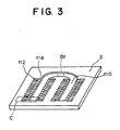
- FIG. 3 is a perspective view showing a horizontal cross section of a head main body in FIG. 1 for explaining an internal construction of the head main body of an ink jet head according to the first embodiment
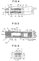
- FIG. 4 is an enlarged plan view showing a portion C of FIG. 1
- FIG. 5 is a cross-sectional view taken along A-A indicated by arrows in FIG. 4
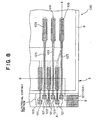
- FIG. 6 is a cross-sectional view taken along B-B indicated by arrows in FIG. 5
- FIG. 7 is a cross-sectional view showing a joint portion thereof.
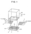
- the ink jet head 100 has a plurality of nozzles 120 (see FIG. 5) for discharging ink supplied from an ink tank (ink supply section) 50, and is made up of a head main body 3 and a joint section 8 as shown in FIG. 1.
- the head main body 3 internally includes a common ink passage 110, and each of the plurality of nozzles 120 has a pressure chamber 112, a pressurizer 140 and ink supply passages 114.
- the pressure chamber 112 is made to be filled up with ink, and communicate through a connecting passage 116 with the nozzle 120.
- the diaphragm 104 is made with an elastically deformable metal thin-film (a thickness of approximately several m), such as chromium or nickel, having an electrical conductive property and some degree of rigidity, and constitutes a surface which is in opposed relation to a portion of the pressure chamber 112, concretely, a surface of the pressure chamber 112 where the connecting passage 116 exists.
- an elastically deformable metal thin-film a thickness of approximately several m
- chromium or nickel having an electrical conductive property and some degree of rigidity
- a thin-film-like piezoelectric element 108 is formed on a surface of the diaphragm 104 which lies on the opposite side to the pressure chamber 112.
- This piezoelectric element 108 is made of a piezo ceramic or the like, and these diaphragm 104 and piezoelectric element 108 constitute a bimorph laminated member.
- the common ink passage 110 is made into a U-like space configuration in the interior of the head main body 3, and the substantially central position thereof is made to communicate with a communicating passage 81. Moreover, this common ink passage 110 is made to communicate with the ink supply passages 114 and an ink supply port 51 of the ink tank 50.
- the pressure chambers 112 are arranged in order in a direction indicated by an arrow C in FIGS. 4 and 6.
- the joint section 8 is made to surround the discrete electrodes 109 on the surface holding the discrete electrodes 109, contact portions (which will be mentioned later) and a wiring pattern (which will be mentioned later).
- a polyimide 126 is placed in an area on the diaphragm 104, where the piezoelectric element 108 and the discrete electrode 109 are absent, for the electrical insulation.
- FIG. 11 is an illustration for explaining an ink jet head manufacturing method according to the first embodiment
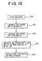
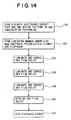
- FIGs. 12 to 14 are flow charts for explaining this manufacturing method.
- the second-layer dry film resist 103 (equivalent to the dry film resist 103d in FIG. 5) is laminated on the first-layer dry film resist 103 (103e), and the portions corresponding to the pressure chambers 112, the ink supply passages 114 and the common ink passage 110 are exposed through the use of masking (step B30 in FIG. 13).
- a dry film resist is laminated as an adhesion layer on the rear surface of the stainless plate 105b, and the portions corresponding to the connecting passages 116 and the common ink passage 110 are exposed through the use of masking (step B40 in FIG. 13).
- the illustration of this adhesion layer is omitted for convenience only.
- step B50 in FIG. 13 the dry film resists on both the surfaces of the substrate are developed, thereby forming a (B) layer shown by circled numeral 5 of FIG. 11(B) (step B50 in FIG. 13).
- a (C) layer is formed by laminating a bimorph laminated member and a dry film resist (step A30 in FIG. 12).
- the dry film resists are developed (step C60 in FIG. 14), and the piezoelectric element 108 to the dry film resist 103c in FIG. 5 are laminated on the MgO substrate 122 to form a laminated member, and as shown by circled numeral 6 of FIG. 11(C) a stainless plate 105a in which the portions corresponding to the pressure chambers 112 and the common ink passage 110 are removed in advance by etching is joined onto the dry film resist 103c (step C70 in FIG. 14).
- the dry film resists 103a to 103e are cured when pressed and heated, thereby producing an integrated construction of the MgO substrate 122 to the nozzle plate 106.
- the step of removing the MgO substrate 122 for the formation of the joint section 8 is not limited to the implementation after the (A) layer to the (C) layer are joined and cured, but, for example, it can also be conducted after the formation of the (C) layer, and all changes which do not constitute departures from the spirit and scope of the invention are acceptable.
- the joint section 8 enhances the rigidity of the head main body 3, in manufacturing the ink jet head 100, the head main body 3 becomes unbreakable, which leads to the improvement of productivity thereof.
- the discrete electrode 109 and the contact portion 121 are electrically connected to each other through a thin-film made wiring pattern 123, and this eliminates the need for the air wiring or the like using the wire bonding or the like, which enhances the nozzle packaging density, achieves the size reduction of the ink jet head, eliminates a possibility of damaging the head main body 3, and preventing short circuits among the wirings.
- the adhesion allowance therefor can be made smaller, which leads to the reduction in the size of the head main body 3, thus resulting in the size reduction of the ink jet head and the printer (ink jet printer) as well.
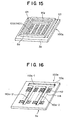
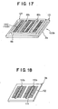
- the ink jet head 100a has a communicating passage 81a with a rectangular opening formed throughout the overall width (right-left direction of paper in FIG. 15) of the head main body 3a.
- the head main body 3a is designed to be connected through this communicating passage 81a to the ink tank.
- the head main body 3a internally includes a common ink passage 110a, and each of the plurality of nozzles has a pressure chamber 112, a pressurizer 140 and an ink supply passage 114.
- the common ink passage 110a is composed of a first common ink passage 110a-1 formed throughout the almost overall width of the head main body 3a, and two second common ink passages 110a-2 formed in parallel with each other and formed perpendicularly to the first common ink passage 110a-1.
- the joint section 8a is formed to protrude from the surface of the head main body 3a (the side where the discrete electrodes 109 exist in the head main body 3a) opposite to the nozzle formation side thereof, and is formed to surround the discrete electrodes 109 on the surface of the head main body 3a where the discrete electrodes 109 exist.
- the joint section 8a is made to surround the communicating passage 81a.
- the ink tank (ink supply part) is joined to the head main body 3a in a manner that the ink tank or an ink tank fixing member is joined through an adhesive or the like to the joint section 8a, and even at the joining of the ink tank to the joint section 8a, this prevents the ink supplied from the ink tank to the communicating passage 81a from flowing out toward the discrete electrode 109 side.
- the substrate made of magnesium oxide (MgO) is partially removed from the head main body 3a by means of photoetching, thereby forming the joint section 8a as a residual portion of the substrate on the head main body 3a.
- a plurality of contact portions 121 are formed in the vicinity of an outer edge portion of the head main body 3, concretely, outside the joint section 8a.
- the ink jet head in addition to the effects similar to those of the first embodiment mentioned above, since the ink from the ink tank is supplied through the communicating passage 81a with the rectangular cross section, formed throughout the almost overall width of the head main body 3a, and the common ink passage 110a-1 to the head main body 3a, the ink can stably be supplied even to the terminal portion of the common ink passage 110, that is, the pressure chambers 112 located in the vicinity of the common ink passage 110a-2 side opposite to the side connected to the common ink passage 110a-1.
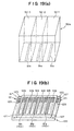
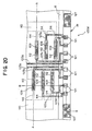
- an ink jet head 100b according to this second modification has a plurality of nozzles (not shown) for discharging ink supplied from an ink tank (ink supply section; not shown), and is made up of a head main body 3b and a joint section 8b.
- the head main body 3c is made to be connected through these communicating passages 81b to the ink tank 50a shown in FIG. 19(b).
- the wiring patterns 123a are formed by means of patterning, and hence, the wiring patterns 123a, the discrete electrodes 109 and the contact portions 121 are made integrally from the same material in the form of a thin film on the same plane.
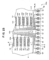
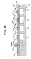
- FIGs. 23 and 24 show, in the head main body 32, on the surface where the discrete electrodes 109 and others exist, the diaphragm 104 is exposed outside the joint section 8b (8c), that is, in the vicinity of comer portions of the head main body 32, thereby forming the contact portions 127.
- FIGs. 26 to 31 are illustrations for explaining a construction of an ink jet head according to a second embodiment of the present invention.
- FIG. 26 is a perspective view showing a construction of a head main body of the ink jet head according to the second embodiment of the present invention
- FIG. 27 is an illustration of a section indicated by an arrow A in FIG. 26
- FIG. 28 is an enlarged plan view showing a portion B in FIG. 26
- FIG. 29 is a cross-sectional view taken along a line A-A of FIG. 28
- FIG. 30 is an enlarged plan view showing a portion C in FIG. 27, and
- FIG. 31 is a cross-sectional view taken along a line B-B of FIG. 28.
- this joint section 8f the substrate made of magnesium oxide (MgO) is partially removed from the head main body 3g by means of photoetching, thereby forming it as a residual portion of the substrate on the head main body 3g. Moreover, the ink tank (ink supply part) or an ink tank fixing member is adhered through an adhesive or the like to the joint section 8f for joining the ink tank 50 to the head main body 3g.
- MgO magnesium oxide
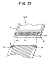
- FIG. 33 is a perspective view showing a construction of an essential part of an ink jet head according to a fourth embodiment of the present invention.
- an ink jet head 500 according to this fourth embodiment has a plurality of nozzles (not shown) each for discharging ink supplied from an ink tank (ink supply section; not shown), and is composed of a head main body 3h and a joint section 8 as shown in FIG. 33.
- a member in place of the stainless plate 105a, a member can also be provided which is made of a material except metals or ceramics, for example, a resin such as PEN or a compound resin such as FRP.
- a resin such as PEN
- FRP compound resin
- the adhesion allowance needed in joining an ink supply part is reducible, so the degree of integration of a head main body is incresable for the size reduction thereof, and the rigidity of the head main body is improvable. Therefore, the head main body is applicable to an ink jet head of an ink jet incorporated printer.
Landscapes
- Engineering & Computer Science (AREA)
- Manufacturing & Machinery (AREA)
- Particle Formation And Scattering Control In Inkjet Printers (AREA)
Applications Claiming Priority (1)
| Application Number | Priority Date | Filing Date | Title |
|---|---|---|---|
| PCT/JP1999/006958 WO2001042023A1 (fr) | 1999-12-10 | 1999-12-10 | Tete a jets d'encre, procede de production de tete a jets d'encre, et imprimante |
Publications (3)
| Publication Number | Publication Date |
|---|---|
| EP1258355A1 true EP1258355A1 (fr) | 2002-11-20 |
| EP1258355A4 EP1258355A4 (fr) | 2003-03-12 |
| EP1258355B1 EP1258355B1 (fr) | 2006-05-24 |
Family
ID=14237533
Family Applications (1)
| Application Number | Title | Priority Date | Filing Date |
|---|---|---|---|
| EP99959763A Expired - Lifetime EP1258355B1 (fr) | 1999-12-10 | 1999-12-10 | Tete a jets d'encre, procede de production de tete a jets d'encre, et imprimante |
Country Status (6)
| Country | Link |
|---|---|
| US (2) | US6637870B2 (fr) |
| EP (1) | EP1258355B1 (fr) |
| JP (1) | JP4269136B2 (fr) |
| KR (1) | KR100469879B1 (fr) |
| DE (1) | DE69931526T2 (fr) |
| WO (1) | WO2001042023A1 (fr) |
Cited By (1)
| Publication number | Priority date | Publication date | Assignee | Title |
|---|---|---|---|---|
| WO2008029650A1 (fr) * | 2006-09-08 | 2008-03-13 | Canon Kabushiki Kaisha | Tête d'éjection de liquide et son procédé de fabrication |
Families Citing this family (11)
| Publication number | Priority date | Publication date | Assignee | Title |
|---|---|---|---|---|
| US6736493B2 (en) * | 2001-05-01 | 2004-05-18 | Brother Kogyo Kabushiki Kaisha | Ink-jet print head |
| KR20030012059A (ko) * | 2001-07-30 | 2003-02-12 | 주식회사 루트스 | 노즐의 집적도를 향상시키는 잉크방을 갖는 잉크젯프린트헤드 및 그의 제조방법 |
| US7059711B2 (en) | 2003-02-07 | 2006-06-13 | Canon Kabushiki Kaisha | Dielectric film structure, piezoelectric actuator using dielectric element film structure and ink jet head |
| US7438395B2 (en) * | 2004-09-24 | 2008-10-21 | Brother Kogyo Kabushiki Kaisha | Liquid-jetting apparatus and method for producing the same |
| JP4867405B2 (ja) * | 2006-03-08 | 2012-02-01 | 富士ゼロックス株式会社 | 液滴吐出ヘッド及び液滴吐出装置 |
| US7552534B2 (en) * | 2006-05-11 | 2009-06-30 | Eastman Kodak Company | Method of manufacturing an integrated orifice plate and electroformed charge plate |
| JP4881126B2 (ja) * | 2006-10-25 | 2012-02-22 | 株式会社東芝 | ノズルプレートの製造方法、および液滴吐出ヘッドの製造方法 |
| JP4557021B2 (ja) * | 2008-02-29 | 2010-10-06 | ブラザー工業株式会社 | 液滴噴射装置 |
| JP5382905B2 (ja) * | 2008-03-10 | 2014-01-08 | 富士フイルム株式会社 | 圧電素子の製造方法及び液体吐出ヘッドの製造方法 |
| JP2009298108A (ja) * | 2008-06-17 | 2009-12-24 | Canon Inc | インクジェット記録ヘッドの製造方法およびインクジェット記録ヘッド |
| JP6950766B2 (ja) * | 2015-05-25 | 2021-10-13 | ブラザー工業株式会社 | 液体吐出装置 |
Family Cites Families (17)
| Publication number | Priority date | Publication date | Assignee | Title |
|---|---|---|---|---|
| JPS6194767A (ja) * | 1984-10-15 | 1986-05-13 | Ricoh Co Ltd | インクジエツトヘツド及びその製造方法 |
| JPH02143861A (ja) | 1988-11-25 | 1990-06-01 | Seiko Epson Corp | インクジェットヘッド |
| EP0500068B1 (fr) * | 1991-02-20 | 1996-10-16 | Canon Kabushiki Kaisha | Tête d'enregistrement à jet d'encre, appareil d'enregistrement l'utilisant et méthode pour sa fabrication |
| JP3062298B2 (ja) * | 1991-07-08 | 2000-07-10 | 東芝テック株式会社 | インクジェットプリンタヘッド |
| US5387314A (en) * | 1993-01-25 | 1995-02-07 | Hewlett-Packard Company | Fabrication of ink fill slots in thermal ink-jet printheads utilizing chemical micromachining |
| DE4336416A1 (de) * | 1993-10-19 | 1995-08-24 | Francotyp Postalia Gmbh | Face-Shooter-Tintenstrahldruckkopf und Verfahren zu seiner Herstellung |
| JPH07329293A (ja) * | 1994-06-03 | 1995-12-19 | Citizen Watch Co Ltd | インクジェットヘッドおよびその製造方法 |
| JP3196799B2 (ja) * | 1994-06-03 | 2001-08-06 | セイコーエプソン株式会社 | 積層型インクジェット記録ヘッド |
| DE69603639T2 (de) * | 1995-03-31 | 2000-04-13 | Canon K.K., Tokio/Tokyo | Verfahren zum Herstellen eines Tintenstrahlkopfes |
| JP3679863B2 (ja) * | 1995-06-12 | 2005-08-03 | セイコーエプソン株式会社 | インクジェット式記録ヘッド |
| JP3492841B2 (ja) * | 1996-02-23 | 2004-02-03 | 富士通株式会社 | インクジェットヘッド及びこれを使用するインクジェットプリンタ |
| US5907333A (en) * | 1997-03-28 | 1999-05-25 | Lexmark International, Inc. | Ink jet print head containing a radiation curable resin layer |
| JP3666177B2 (ja) * | 1997-04-14 | 2005-06-29 | 松下電器産業株式会社 | インクジェット記録装置 |
| JPH1170649A (ja) * | 1997-08-28 | 1999-03-16 | Seiko Epson Corp | インクジェットプリンタヘッド |
| JP3823567B2 (ja) | 1998-10-20 | 2006-09-20 | 富士写真フイルム株式会社 | インクジェット記録ヘッド及びその製造方法及びプリンタ装置 |
| EP1245390A4 (fr) * | 1999-12-10 | 2009-04-01 | Fujifilm Corp | Tete a jet d'encre et imprimante |
| KR100481901B1 (ko) * | 1999-12-10 | 2005-04-11 | 후지 샤신 필름 가부시기가이샤 | 잉크젯 헤드 및 인쇄 장치 |
-
1999
- 1999-12-10 DE DE69931526T patent/DE69931526T2/de not_active Expired - Lifetime
- 1999-12-10 WO PCT/JP1999/006958 patent/WO2001042023A1/fr not_active Ceased
- 1999-12-10 JP JP2001543340A patent/JP4269136B2/ja not_active Expired - Fee Related
- 1999-12-10 EP EP99959763A patent/EP1258355B1/fr not_active Expired - Lifetime
- 1999-12-10 KR KR10-2002-7007161A patent/KR100469879B1/ko not_active Expired - Fee Related
-
2002
- 2002-06-07 US US10/163,617 patent/US6637870B2/en not_active Expired - Lifetime
-
2003
- 2003-08-06 US US10/634,840 patent/US6978543B2/en not_active Expired - Fee Related
Cited By (3)
| Publication number | Priority date | Publication date | Assignee | Title |
|---|---|---|---|---|
| WO2008029650A1 (fr) * | 2006-09-08 | 2008-03-13 | Canon Kabushiki Kaisha | Tête d'éjection de liquide et son procédé de fabrication |
| US8376525B2 (en) | 2006-09-08 | 2013-02-19 | Canon Kabushiki Kaisha | Liquid discharge head and method of manufacturing the same |
| US8622523B2 (en) | 2006-09-08 | 2014-01-07 | Canon Kabushiki Kaisha | Liquid discharge head and method of manufacturing the same |
Also Published As
| Publication number | Publication date |
|---|---|
| US20020154197A1 (en) | 2002-10-24 |
| JP4269136B2 (ja) | 2009-05-27 |
| KR100469879B1 (ko) | 2005-02-02 |
| KR20020086461A (ko) | 2002-11-18 |
| EP1258355A4 (fr) | 2003-03-12 |
| US20040025343A1 (en) | 2004-02-12 |
| WO2001042023A1 (fr) | 2001-06-14 |
| US6637870B2 (en) | 2003-10-28 |
| DE69931526T2 (de) | 2007-04-26 |
| US6978543B2 (en) | 2005-12-27 |
| DE69931526D1 (de) | 2006-06-29 |
| EP1258355B1 (fr) | 2006-05-24 |
Similar Documents
| Publication | Publication Date | Title |
|---|---|---|
| JP4554135B2 (ja) | インクジェットヘッドおよび印刷装置 | |
| JP4526244B2 (ja) | インクジェットヘッド及びインクジェットプリンタ並びにインクジェットヘッドの製造方法 | |
| JPWO2001042017A1 (ja) | インクジェットヘッドおよび印刷装置 | |
| EP1258356B1 (fr) | Tete a jet d'encre et imprimante | |
| EP1258355B1 (fr) | Tete a jets d'encre, procede de production de tete a jets d'encre, et imprimante | |
| JPWO2001042023A1 (ja) | インクジェットヘッドおよびインクジェットヘッドの製造方法並びに印刷装置 | |
| EP1961571B1 (fr) | Tête d'éjection de liquide | |
| JPWO2001042024A1 (ja) | インクジェットヘッドおよび印刷装置 | |
| US11192365B1 (en) | Piezoelectric printhead and printing system | |
| JPH09226115A (ja) | インクジェットプリントヘッド | |
| CN111660671B (zh) | 用多种墨水的压电喷墨打印头及打印系统 | |
| US11345147B2 (en) | Liquid ejection head | |
| US10493760B2 (en) | Liquid jet apparatus and method for manufacturing liquid jet apparatus | |
| JPH09314831A (ja) | インクジェット記録ヘッド | |
| CN111703207B (zh) | 带单层内电极的压电喷墨打印器件 | |
| JP2009166334A (ja) | 液体噴射ヘッド及び液体噴射装置 | |
| JPH07304169A (ja) | 液滴噴射装置 | |
| JPH07156392A (ja) | インクジェット記録装置およびその製造方法 | |
| JP2001179967A (ja) | インクジェット記録ヘッド | |
| JP2002079667A (ja) | インクジェットヘッド及びインクジェット記録装置 | |
| JP2003034018A (ja) | プリントヘッド |
Legal Events
| Date | Code | Title | Description |
|---|---|---|---|
| PUAI | Public reference made under article 153(3) epc to a published international application that has entered the european phase |
Free format text: ORIGINAL CODE: 0009012 |
|
| 17P | Request for examination filed |
Effective date: 20020613 |
|
| AK | Designated contracting states |
Kind code of ref document: A1 Designated state(s): AT BE CH CY DE DK ES FI FR GB GR IE IT LI LU MC NL PT SE |
|
| AX | Request for extension of the european patent |
Free format text: AL;LT;LV;MK;RO;SI |
|
| A4 | Supplementary search report drawn up and despatched |
Effective date: 20030127 |
|
| RIC1 | Information provided on ipc code assigned before grant |
Ipc: 7B 41J 2/14 B Ipc: 7B 41J 2/16 A |
|
| RBV | Designated contracting states (corrected) |
Designated state(s): AT BE CH DE FR GB LI |
|
| RAP1 | Party data changed (applicant data changed or rights of an application transferred) |
Owner name: FUJI PHOTO FILM CO., LTD. |
|
| GRAP | Despatch of communication of intention to grant a patent |
Free format text: ORIGINAL CODE: EPIDOSNIGR1 |
|
| RBV | Designated contracting states (corrected) |
Designated state(s): DE FR GB |
|
| GRAS | Grant fee paid |
Free format text: ORIGINAL CODE: EPIDOSNIGR3 |
|
| GRAA | (expected) grant |
Free format text: ORIGINAL CODE: 0009210 |
|
| AK | Designated contracting states |
Kind code of ref document: B1 Designated state(s): DE FR GB |
|
| REG | Reference to a national code |
Ref country code: GB Ref legal event code: FG4D |
|
| REF | Corresponds to: |
Ref document number: 69931526 Country of ref document: DE Date of ref document: 20060629 Kind code of ref document: P |
|
| ET | Fr: translation filed | ||
| PLBE | No opposition filed within time limit |
Free format text: ORIGINAL CODE: 0009261 |
|
| STAA | Information on the status of an ep patent application or granted ep patent |
Free format text: STATUS: NO OPPOSITION FILED WITHIN TIME LIMIT |
|
| REG | Reference to a national code |
Ref country code: GB Ref legal event code: 732E |
|
| 26N | No opposition filed |
Effective date: 20070227 |
|
| RAP2 | Party data changed (patent owner data changed or rights of a patent transferred) |
Owner name: FUJIFILM CORPORATION |
|
| REG | Reference to a national code |
Ref country code: FR Ref legal event code: TP Ref country code: FR Ref legal event code: CD |
|
| REG | Reference to a national code |
Ref country code: FR Ref legal event code: PLFP Year of fee payment: 17 |
|
| PGFP | Annual fee paid to national office [announced via postgrant information from national office to epo] |
Ref country code: GB Payment date: 20151209 Year of fee payment: 17 Ref country code: DE Payment date: 20151201 Year of fee payment: 17 |
|
| PGFP | Annual fee paid to national office [announced via postgrant information from national office to epo] |
Ref country code: FR Payment date: 20151110 Year of fee payment: 17 |
|
| REG | Reference to a national code |
Ref country code: DE Ref legal event code: R119 Ref document number: 69931526 Country of ref document: DE |
|
| GBPC | Gb: european patent ceased through non-payment of renewal fee |
Effective date: 20161210 |
|
| REG | Reference to a national code |
Ref country code: FR Ref legal event code: ST Effective date: 20170831 |
|
| PG25 | Lapsed in a contracting state [announced via postgrant information from national office to epo] |
Ref country code: FR Free format text: LAPSE BECAUSE OF NON-PAYMENT OF DUE FEES Effective date: 20170102 |
|
| PG25 | Lapsed in a contracting state [announced via postgrant information from national office to epo] |
Ref country code: DE Free format text: LAPSE BECAUSE OF NON-PAYMENT OF DUE FEES Effective date: 20170701 Ref country code: GB Free format text: LAPSE BECAUSE OF NON-PAYMENT OF DUE FEES Effective date: 20161210 |