EP1258702A2 - Dispositif et procédé pour l' alignement des arbres de machines - Google Patents
Dispositif et procédé pour l' alignement des arbres de machines Download PDFInfo
- Publication number
- EP1258702A2 EP1258702A2 EP02008681A EP02008681A EP1258702A2 EP 1258702 A2 EP1258702 A2 EP 1258702A2 EP 02008681 A EP02008681 A EP 02008681A EP 02008681 A EP02008681 A EP 02008681A EP 1258702 A2 EP1258702 A2 EP 1258702A2
- Authority
- EP
- European Patent Office
- Prior art keywords
- machine
- shafts
- reflector
- determining
- distance
- Prior art date
- Legal status (The legal status is an assumption and is not a legal conclusion. Google has not performed a legal analysis and makes no representation as to the accuracy of the status listed.)
- Withdrawn
Links
- 238000000034 method Methods 0.000 title claims abstract description 17
- 238000005259 measurement Methods 0.000 claims abstract description 28
- 230000003287 optical effect Effects 0.000 claims description 11
- 238000011156 evaluation Methods 0.000 claims description 5
- 230000008878 coupling Effects 0.000 claims description 4
- 238000010168 coupling process Methods 0.000 claims description 3
- 238000005859 coupling reaction Methods 0.000 claims description 3
- 230000005693 optoelectronics Effects 0.000 claims 2
- 230000008569 process Effects 0.000 description 4
- 230000005540 biological transmission Effects 0.000 description 2
- 230000000694 effects Effects 0.000 description 2
- 230000008901 benefit Effects 0.000 description 1
- 238000006073 displacement reaction Methods 0.000 description 1
- 238000005516 engineering process Methods 0.000 description 1
- 230000006870 function Effects 0.000 description 1
- 230000003993 interaction Effects 0.000 description 1
- 239000003550 marker Substances 0.000 description 1
- 238000004377 microelectronic Methods 0.000 description 1
- 238000005192 partition Methods 0.000 description 1
Images




Classifications
-
- G—PHYSICS
- G01—MEASURING; TESTING
- G01B—MEASURING LENGTH, THICKNESS OR SIMILAR LINEAR DIMENSIONS; MEASURING ANGLES; MEASURING AREAS; MEASURING IRREGULARITIES OF SURFACES OR CONTOURS
- G01B11/00—Measuring arrangements characterised by the use of optical techniques
- G01B11/26—Measuring arrangements characterised by the use of optical techniques for measuring angles or tapers; for testing the alignment of axes
- G01B11/27—Measuring arrangements characterised by the use of optical techniques for measuring angles or tapers; for testing the alignment of axes for testing the alignment of axes
- G01B11/272—Measuring arrangements characterised by the use of optical techniques for measuring angles or tapers; for testing the alignment of axes for testing the alignment of axes using photoelectric detection means
Definitions
- the invention relates to a device for aligning machine shafts.
- Such a device is known from US 4,463,438, inventor Zatezalo.
- the said The device provides for the use of mechanical measuring means. Is accordingly The achievable accuracy when aligning machine shafts is limited and depends on various mechanical boundary conditions, for example the sag of the Measuring means.
- a similar device with significantly improved accuracy is described in the EP 0145745, inventor Lysen. Instead of mechanical measuring pointers, the EP sees 0145745 those based on a laser beam. This allowed the utility value of shaft alignment instruments can be increased drastically.
- the each provided microelectronics and measurement methodology a computer-aided, accurate and Aligning machine shafts much more comfortably than was previously possible.
- two separate laser light transmit and receive devices provided, namely one for determining offset dimensions on shafts, and one for the Determination of distances of the machine fastening elements among each other or relative to a plane of symmetry between the machine shafts.
- a special Embodiment of the invention is only a single laser light transmission and Receiving device provided, which alternately for the provisions of Dimensions and distances are used.
- a characteristic of the invention is the procedure that determined electronically Distances between the machine fasteners in an automatic manner To perform the calculation process for determining correction values with which the Displacement values are calculated, based on which an optimal alignment of those involved Machines and machine shafts can be run. Accordingly, it is possible said first computing unit and said evaluation and computing device for Determine the distance of machine fasteners in a single summarize electronic circuit.
- This electronic circuit can be used with a single user interface (as output device) and a single Input device are in a functional connection. This way it will now possible, also the previously manual measurement process to determine Dimensions to do with the help of computers, which inadvertently brings in Measurement errors is significantly reduced and the alignment measure is simplified overall.
- the invention is suitable for differently designed alignment devices To find use. These alignment devices can therefore use a single laser beam Provide for the determination of shaft offsets, or two separate laser beams.
- the invention provides optical measuring means with which the distances, as specified, for example, in US 4,463,438, can be detected automatically.
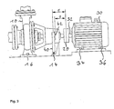
- Two Machines 10, 20 can by means of bolts and nuts 14, 34, 36 etc. on one Mounting level can be brought into a desired position. To position the Machines in the vertical direction can be used as shims this is known per se, but is not shown in the drawing.
- Waves 12, 32 of the machines 10, 20 are operatively connected by means of a coupling, their longitudinal axes should be be coaxial identical to avoid wear and machine damage.
- FIG. 1 there is a portable computer 50 provided with input device 52 and display 53, which in its main function mechanical or optical measuring means (not shown in Fig. 1) for determining the queries translational and angular misalignment of the machines 10, 30. From such Certain measured values are used to calculate the desired correction information with which the Machines can be brought into ideal positions if there is a misalignment should.
- FIG. 1 it is shown how the relevant ones are first used by means of the computer 50 Machine dimensions can be recorded.
- the distance between computer 50 and reflector 42 Either by measuring the transit time, or by Triangulation, it is possible to measure the distance between computer 50 and reflector 42 in to determine with sufficient accuracy.
- the longitudinal axis of the Computer 50 manually aligned to a central plane of the clutch 20 because of this An important reference plane is defined.
- the reflector 42 can, depending on optical measuring method used, be made in different technologies. Usually it has a diffuse reflection behavior, so that its orientation is relative to the computer 50 is not critical.
- a stand 40 is provided for positioning the reflector 42 suitable length provided.
- the stand 40 can be equipped with a magnetic base 44, but it can also be set up directly on the mounting level belonging to the machine.
- the reflector 42 can therefore be positioned manually so that the axis of symmetry of the Tripods 40 to lie parallel to the longitudinal axis of the nut 14 or the associated bolt comes after the distance measurement has taken place (for which purpose the computer 50 together with its transmit and Receiving device 54 is used), the reflector 42 can be used for a subsequent one Measurement from one measuring position to the next (c.f. Fig. 2 and 3). There are typically perform four such distance measurements and in the computer's memory for save the further alignment measures.
- the computer 50 has an input device 52 and a screen 53.
- the input device can be a conventional keyboard, or be realized by means of a one-button selection device.
- It is advantageous to use the calculator a user interface on an alphanumeric, graphic or acoustic basis equip. An operator can then easily the different Measurement tasks successively and according to specified or selectable partitions work off.
- FIG. 2 it is shown how the tripod 40 above a mounting nut 16 for the Measurement of the distance dimension d "is positioned.
- FIG. 3 shown as the tripod 40 above the fastening nut 14, which the machine base 18th is assigned, is positioned for the measurement of the distance dimension d '.
- the computer software can be designed so that the optically determined distance d automatically into the the underlying distance d 'is converted, if this is necessary and the Reflector 42 is not aligned with the fastening nut 14 anyway.
- FIG. 1 An alternative embodiment of the invention is shown in FIG.
- a light beam 56 ′ is provided, which is transmitted through a laser light source 60 is produced.
- This light source can be the same one that is primarily used to measure the radial and angular offset of the shaft pieces 12, 32 is used (associated receiver or reflector not shown).
- the laser light source interacts with an associated one Receiving device (in Fig. 4, 5 not shown) a distance measurement, so that the relevant distances between the coupling center and fastening screws 14, 16 can be registered, or equivalent measurements, which are characterized by a constant differ.
- So pulsed light is sent to the reflector 42, the reflected light is sensed with a fast photodetector, and due to the running time the distance to the reflector 42 determined electronically.
- the laser light source 60 temporarily attached to the shaft 32 with a known clamping device 70.
- the Laser light source 60 reclamped or repositioned and then used for distance measurement with respect to the fastening nuts 34, 36. This is shown, for example, in FIG associated laser light beam is identified by reference numeral 56 ".
- two laser light sources can be used.
- these can be on their associated shaft sections 12, 32 be twisted against each other and then in interaction with not just one, but can be used with associated separate reflectors 42.
- FIG. 6 shows a further embodiment of the invention, which is characterized by a characterized symmetrically arranged reflector 142, which during the individual Distance measurements do not have to be repositioned or repositioned.
- This reflector is essentially flat. It preferably has two back to back arranged reflection planes.
- the said reflector is arranged so that the two Reflection planes practically coincide with the central coupling plane, which is the axes of the machines involved cuts vertically.
- Magnet holder 144 with associated tripod rod provided.
- the tripod rod can advantageously be extended or shortened in the manner of a telescope. It can but other tripod arrangements are used, e.g. those that are based on the Hall floor. As shown in FIG.
- the computer 50 is moving in the direction of a The machine axis moves until its coordinate value in this regard coincides with that of one machine foot to be measured or an associated fastening screw or bolt matches.
- the position between the computer 50 then becomes from such a position and optically measure a first reflector side of the reflector 142, as is shown by the drawn light beam 56 '' 'is clear.
- This measurement process is for everyone coordinates of interest repeated. It can be relieved and with better precision if the computer has a transmitter for a marking beam 156 having.
- the light rays that create this marker beam span a plane which is oriented substantially perpendicular to the measuring beam 56 '".
- the computer 50 is except for small residual errors positioned correctly.
Landscapes
- Physics & Mathematics (AREA)
- General Physics & Mathematics (AREA)
- Length Measuring Devices By Optical Means (AREA)
- Laser Surgery Devices (AREA)
- Optical Measuring Cells (AREA)
- Particle Accelerators (AREA)
Applications Claiming Priority (4)
| Application Number | Priority Date | Filing Date | Title |
|---|---|---|---|
| DE2001124287 DE10124287A1 (de) | 2001-05-17 | 2001-05-17 | Vorrichtung und Verfahren zum Ausrichten von Maschinenwellen |
| DE10124287 | 2001-05-17 | ||
| DE10132142A DE10132142A1 (de) | 2001-05-17 | 2001-06-29 | Vorrichtung und Verfahren zum Ausrichten von Maschinenwellen |
| DE10132142 | 2001-06-29 |
Publications (2)
| Publication Number | Publication Date |
|---|---|
| EP1258702A2 true EP1258702A2 (fr) | 2002-11-20 |
| EP1258702A3 EP1258702A3 (fr) | 2004-05-19 |
Family
ID=26009333
Family Applications (1)
| Application Number | Title | Priority Date | Filing Date |
|---|---|---|---|
| EP02008681A Withdrawn EP1258702A3 (fr) | 2001-05-17 | 2002-04-18 | Dispositif et procédé pour l' alignement des arbres de machines |
Country Status (3)
| Country | Link |
|---|---|
| US (1) | US6784986B2 (fr) |
| EP (1) | EP1258702A3 (fr) |
| DE (1) | DE10132142A1 (fr) |
Families Citing this family (16)
| Publication number | Priority date | Publication date | Assignee | Title |
|---|---|---|---|---|
| US6792688B2 (en) * | 2000-08-09 | 2004-09-21 | Prüftechnik Dieter Busch AG | Process and device for determining the alignment of a body with regard to a reference direction |
| DE10301304A1 (de) * | 2003-01-15 | 2004-08-12 | Prüftechnik Dieter Busch AG | Verfahren und Messvorrichtung zum Ermitteln der Ausrichtung eines zylindrischen Körpers |
| DE102004011404A1 (de) * | 2004-03-05 | 2005-09-22 | Prüftechnik Dieter Busch AG | Messgerät zur Bestimmung der Geradheit von Wellen oder Wellentunneln |
| US7174649B1 (en) * | 2005-11-08 | 2007-02-13 | Danny Harris | Precision shaft alignment system |
| DE102008010916A1 (de) * | 2008-02-25 | 2009-08-27 | Prüftechnik Dieter Busch AG | Verfahren und Vorrichtung zur Ermittlung einer Ausrichtung von zwei drehbar gelagerten Maschinenteilen, einer Ausrichtung von zwei hohlzylinderförmigen Maschinenteilen oder zur Prüfung einer Komponente auf Geradheit entlang einer Längsseite |
| US8196304B1 (en) | 2008-09-09 | 2012-06-12 | Mcbride Matthew J | Method and apparatus for aligning a wind turbine generator |
| US8209875B1 (en) | 2009-10-08 | 2012-07-03 | Danny Harris | Precision shaft alignment system |
| DE102011004434A1 (de) | 2011-02-21 | 2012-08-23 | Schaeffler Technologies Gmbh & Co. Kg | Laser-Ausrichtsystem zur Messung einer Ausrichtung rotierender Maschinenteile sowie Verfahren zur Aufbereitung von Messergebnissen eines Laser-Ausrichtungssystems |
| DE102012023201A1 (de) * | 2012-11-28 | 2014-05-28 | Prüftechnik Dieter Busch AG | Kupplungsvorrichtung und Verfahren zum Bestimmen der Fehlausrichtung von zwei Wellen |
| CN104956178A (zh) * | 2013-01-25 | 2015-09-30 | 中国电力株式会社 | 距离测定系统、距离测定方法 |
| US20160190906A1 (en) * | 2014-12-25 | 2016-06-30 | Ballou De'Wana | Geomagnetic Device |
| DE102015205710A1 (de) | 2015-03-30 | 2016-10-06 | Prüftechnik Dieter Busch AG | Verfahren zum Anordnen eines Laserausrichtsystems an einer Vorrichtung mit zwei durch eine Kupplung miteinander verbundenen Wellen und Laserausrichtsystem mit einer ersten Einrichtung und einer zweiten Einrichtung |
| RU171844U1 (ru) * | 2016-09-06 | 2017-06-19 | Публичное акционерное общество "КАМАЗ" | Устройство для центровки двс на испытательном стенде |
| US10435277B1 (en) * | 2017-05-19 | 2019-10-08 | J & M Turbine Tools, LLC | Portable crane for maintaining a wind turbine generator |
| US11300404B2 (en) | 2018-10-21 | 2022-04-12 | Shoreline Alignment & Vibration, LLC | Alignment of rotational shafts |
| JP2025014449A (ja) * | 2023-07-18 | 2025-01-30 | 株式会社東芝 | ロータセンタリング計測方法、ロータアライメント調整支援方法及びロータセンタリング計測装置 |
Citations (4)
| Publication number | Priority date | Publication date | Assignee | Title |
|---|---|---|---|---|
| EP0145745A1 (fr) | 1983-06-03 | 1985-06-26 | Busch Dieter & Co Prueftech | Installation pour determiner des erreurs d'alignement pour des arbres disposes les uns derriere les autres. |
| US4637715A (en) | 1983-09-01 | 1987-01-20 | Rikagaku Kenkyusho | Optical distance measuring apparatus |
| US4709485A (en) | 1986-12-04 | 1987-12-01 | Mobil Oil Corporation | Shaft alignment method and apparatus |
| DE4335075A1 (de) | 1993-10-14 | 1995-04-20 | Rudolf Joos | Reinigungsvorrichtung, insbesondere für Tierhufe |
Family Cites Families (12)
| Publication number | Priority date | Publication date | Assignee | Title |
|---|---|---|---|---|
| US4033042A (en) | 1974-10-10 | 1977-07-05 | Bently Nevada Corporation | Shaft alignment apparatus and method |
| US4283688A (en) * | 1979-11-26 | 1981-08-11 | The United States Of America As Represented By The Secretary Of The Air Force | Laser autoalignment system |
| US4463438A (en) | 1981-12-11 | 1984-07-31 | Industrial Maintenance Systems, Inc. | Shaft alignment calculator |
| DE3531615A1 (de) * | 1985-09-04 | 1987-03-05 | Busch Dieter & Co Prueftech | Vorrichtung zum feststellen und ueberwachen von aenderungen der position von wellen |
| DE3911307C2 (de) * | 1989-04-07 | 1998-04-09 | Busch Dieter & Co Prueftech | Verfahren zum Feststellen, ob zwei hintereinander angeordnete Wellen hinsichtlich ihrer Mittelachse fluchten oder versetzt sind |
| US5077905A (en) * | 1990-06-04 | 1992-01-07 | Murray Jr Malcolm G | Laser alignment mount assembly and method |
| US5056237A (en) | 1990-07-02 | 1991-10-15 | Spm Instrument Inc. | Electronic indicating device for coaxially aligning a pair of rotary members |
| ATA205592A (de) * | 1992-10-19 | 1994-09-15 | Tabarelli Werner | Einrichtung zur erfassung der lage eines objektes |
| US5691523A (en) | 1996-12-03 | 1997-11-25 | Align-It Corporation | Machinery shaft alignment calculator |
| EP0894240B1 (fr) * | 1997-01-22 | 2003-08-27 | Prüftechnik Dieter Busch Ag | Dispositif de mesure electro-optique permettant de determiner la position relative de deux corps l'un par rapport a l'autre ou de deux surfaces de corps l'une par rapport a l'autre |
| US5896672A (en) | 1997-06-27 | 1999-04-27 | Harris; G. Danny | Precision shaft alignment system |
| US6434849B1 (en) * | 2000-01-24 | 2002-08-20 | Pruftechnik Dieter Busch Ag | Method for determining a lateral and/or angular offset between two rotatable parts |
-
2001
- 2001-06-29 DE DE10132142A patent/DE10132142A1/de not_active Ceased
-
2002
- 2002-04-18 EP EP02008681A patent/EP1258702A3/fr not_active Withdrawn
- 2002-05-17 US US10/147,305 patent/US6784986B2/en not_active Expired - Fee Related
Patent Citations (4)
| Publication number | Priority date | Publication date | Assignee | Title |
|---|---|---|---|---|
| EP0145745A1 (fr) | 1983-06-03 | 1985-06-26 | Busch Dieter & Co Prueftech | Installation pour determiner des erreurs d'alignement pour des arbres disposes les uns derriere les autres. |
| US4637715A (en) | 1983-09-01 | 1987-01-20 | Rikagaku Kenkyusho | Optical distance measuring apparatus |
| US4709485A (en) | 1986-12-04 | 1987-12-01 | Mobil Oil Corporation | Shaft alignment method and apparatus |
| DE4335075A1 (de) | 1993-10-14 | 1995-04-20 | Rudolf Joos | Reinigungsvorrichtung, insbesondere für Tierhufe |
Also Published As
| Publication number | Publication date |
|---|---|
| US20030055536A1 (en) | 2003-03-20 |
| EP1258702A3 (fr) | 2004-05-19 |
| DE10132142A1 (de) | 2003-02-13 |
| US6784986B2 (en) | 2004-08-31 |
Similar Documents
| Publication | Publication Date | Title |
|---|---|---|
| EP1258702A2 (fr) | Dispositif et procédé pour l' alignement des arbres de machines | |
| DE3911307C2 (de) | Verfahren zum Feststellen, ob zwei hintereinander angeordnete Wellen hinsichtlich ihrer Mittelachse fluchten oder versetzt sind | |
| DE3781519T2 (de) | Standortbestimmungsgeraet. | |
| DE3784047T2 (de) | Kalibrierungsverfahren für ein Koordinatenmessgerät und ähnliche Geräte. | |
| DE69516871T2 (de) | Verfahren zum lokaliseren eines trieders im raum | |
| DE69120867T2 (de) | System und Verfahren zur rechnergestützten Positionierung | |
| EP2093537B1 (fr) | Système et procédé pour déterminer l'alignement de deux pièces de machine rotatives | |
| DE69330466T2 (de) | Verfahren und vorrichtung zur bestimmung der ausrichtung von kraftfahrzeugrädern | |
| DE2934347C2 (de) | Verfahren und Prüfgerät zum Prüfen des Zahnflankenprofils von Zahnrädern großen Durchmessers | |
| EP1420264A1 (fr) | Procédé et dispositif de calibration d'un système de mesure | |
| EP0362626A2 (fr) | Bâti d'examen pour appareil de mesure de coordonnées | |
| EP1277028B1 (fr) | Instrument de mesure a coordonnees ou machine-outil | |
| DE4034302A1 (de) | Laserausrichtungs-steuersystem | |
| EP1236971B1 (fr) | Procédé et dispositif pour la détermination de l'orientation axiale de deux axes de machines | |
| DE3116235A1 (de) | Werkstatt-messgeraet zum ueberpruefen der abmessungsgenauigkeit grosser objekte | |
| EP1071924B1 (fr) | Procede de mesure laser destine a determiner l'azimut et l'elevation de deux broches d'outil par rapport a un plan de reference | |
| EP0481278A1 (fr) | Procédé et installation de mesure pour localisation de points dans l'espace | |
| DE10048096A1 (de) | Verfahren zur Kalibrierung eines messenden Sensors auf einem Koordinatenmeßgerät | |
| DE68906669T2 (de) | Messsystem fuer eine werkzeugeinstellung in einer werkzeugmaschine. | |
| DE102011055119A1 (de) | Vorrichtung und Verfahren zur Bestimmung der Orientierung zweier über zwei Kreuzgelenke und eine dritte Welle verbundener Wellen mit einem Drehgelenk | |
| EP0563058B1 (fr) | Procede et capteur de position pour la determination de la position d'un corps de positionnement par rapport a un corps de reference | |
| DE102011055118A1 (de) | Verfahren zur Bestimmung der Orientierung zweier über zwei Kreuzgelenke und eine dritte Welle verbundener Wellen in der Ebene der drei Wellen | |
| DE3781674T2 (de) | Positionsbestimmungsverfahren innerhalb des messraumes eines koordinatenmessgeraetes und dergleichen und system dafuer. | |
| DE69119975T2 (de) | Korrektureinrichtung für Koordinatensysteme bei Werkzeugmaschinen | |
| DE10021491B4 (de) | Verfahren und Vorrichtung zum Ermitteln des Schwerpunktes eines anbaubaren Werkstücks, insbesondere einer Kolbenmaschine |
Legal Events
| Date | Code | Title | Description |
|---|---|---|---|
| PUAI | Public reference made under article 153(3) epc to a published international application that has entered the european phase |
Free format text: ORIGINAL CODE: 0009012 |
|
| AK | Designated contracting states |
Kind code of ref document: A2 Designated state(s): AT BE CH CY DE DK ES FI FR GB GR IE IT LI LU MC NL PT SE TR |
|
| AX | Request for extension of the european patent |
Free format text: AL;LT;LV;MK;RO;SI |
|
| PUAL | Search report despatched |
Free format text: ORIGINAL CODE: 0009013 |
|
| AK | Designated contracting states |
Kind code of ref document: A3 Designated state(s): AT BE CH CY DE DK ES FI FR GB GR IE IT LI LU MC NL PT SE TR |
|
| AX | Request for extension of the european patent |
Extension state: AL LT LV MK RO SI |
|
| RIC1 | Information provided on ipc code assigned before grant |
Ipc: 7G 01B 21/16 B Ipc: 7G 01B 21/24 B Ipc: 7G 01B 11/14 B Ipc: 7G 01B 11/02 B Ipc: 7G 01B 11/27 A |
|
| 17P | Request for examination filed |
Effective date: 20040816 |
|
| AKX | Designation fees paid |
Designated state(s): AT BE CH CY DE DK ES FI FR GB GR IE IT LI LU MC NL PT SE TR |
|
| 17Q | First examination report despatched |
Effective date: 20090713 |
|
| STAA | Information on the status of an ep patent application or granted ep patent |
Free format text: STATUS: THE APPLICATION IS DEEMED TO BE WITHDRAWN |
|
| 18D | Application deemed to be withdrawn |
Effective date: 20140624 |