EP1259023B1 - RDS Dekoder - Google Patents
RDS Dekoder Download PDFInfo
- Publication number
- EP1259023B1 EP1259023B1 EP20010111694 EP01111694A EP1259023B1 EP 1259023 B1 EP1259023 B1 EP 1259023B1 EP 20010111694 EP20010111694 EP 20010111694 EP 01111694 A EP01111694 A EP 01111694A EP 1259023 B1 EP1259023 B1 EP 1259023B1
- Authority
- EP
- European Patent Office
- Prior art keywords
- zero crossing
- rds
- check
- found
- samples
- Prior art date
- Legal status (The legal status is an assumption and is not a legal conclusion. Google has not performed a legal analysis and makes no representation as to the accuracy of the status listed.)
- Expired - Lifetime
Links
- 238000005070 sampling Methods 0.000 claims description 15
- 230000001360 synchronised effect Effects 0.000 claims description 14
- 238000000034 method Methods 0.000 claims description 12
- 238000012795 verification Methods 0.000 claims description 10
- 238000004590 computer program Methods 0.000 claims description 4
- 230000000737 periodic effect Effects 0.000 claims description 3
- 238000011084 recovery Methods 0.000 description 18
- 239000010432 diamond Substances 0.000 description 4
- 230000005236 sound signal Effects 0.000 description 4
- 230000003247 decreasing effect Effects 0.000 description 1
- 230000001419 dependent effect Effects 0.000 description 1
- 230000001788 irregular Effects 0.000 description 1
Images

Classifications
-
- H—ELECTRICITY
- H04—ELECTRIC COMMUNICATION TECHNIQUE
- H04H—BROADCAST COMMUNICATION
- H04H40/00—Arrangements specially adapted for receiving broadcast information
- H04H40/18—Arrangements characterised by circuits or components specially adapted for receiving
-
- H—ELECTRICITY
- H03—ELECTRONIC CIRCUITRY
- H03L—AUTOMATIC CONTROL, STARTING, SYNCHRONISATION OR STABILISATION OF GENERATORS OF ELECTRONIC OSCILLATIONS OR PULSES
- H03L7/00—Automatic control of frequency or phase; Synchronisation
- H03L7/06—Automatic control of frequency or phase; Synchronisation using a reference signal applied to a frequency- or phase-locked loop
- H03L7/08—Details of the phase-locked loop
- H03L7/085—Details of the phase-locked loop concerning mainly the frequency- or phase-detection arrangement including the filtering or amplification of its output signal
- H03L7/091—Details of the phase-locked loop concerning mainly the frequency- or phase-detection arrangement including the filtering or amplification of its output signal the phase or frequency detector using a sampling device
-
- H—ELECTRICITY
- H04—ELECTRIC COMMUNICATION TECHNIQUE
- H04L—TRANSMISSION OF DIGITAL INFORMATION, e.g. TELEGRAPHIC COMMUNICATION
- H04L7/00—Arrangements for synchronising receiver with transmitter
- H04L7/02—Speed or phase control by the received code signals, the signals containing no special synchronisation information
- H04L7/033—Speed or phase control by the received code signals, the signals containing no special synchronisation information using the transitions of the received signal to control the phase of the synchronising-signal-generating means, e.g. using a phase-locked loop
- H04L7/0334—Processing of samples having at least three levels, e.g. soft decisions
-
- H—ELECTRICITY
- H03—ELECTRONIC CIRCUITRY
- H03L—AUTOMATIC CONTROL, STARTING, SYNCHRONISATION OR STABILISATION OF GENERATORS OF ELECTRONIC OSCILLATIONS OR PULSES
- H03L2207/00—Indexing scheme relating to automatic control of frequency or phase and to synchronisation
- H03L2207/14—Preventing false-lock or pseudo-lock of the PLL
-
- H—ELECTRICITY
- H04—ELECTRIC COMMUNICATION TECHNIQUE
- H04H—BROADCAST COMMUNICATION
- H04H20/00—Arrangements for broadcast or for distribution combined with broadcast
- H04H20/28—Arrangements for simultaneous broadcast of plural pieces of information
- H04H20/33—Arrangements for simultaneous broadcast of plural pieces of information by plural channels
- H04H20/34—Arrangements for simultaneous broadcast of plural pieces of information by plural channels using an out-of-band subcarrier signal
-
- H—ELECTRICITY
- H04—ELECTRIC COMMUNICATION TECHNIQUE
- H04H—BROADCAST COMMUNICATION
- H04H2201/00—Aspects of broadcast communication
- H04H2201/10—Aspects of broadcast communication characterised by the type of broadcast system
- H04H2201/13—Aspects of broadcast communication characterised by the type of broadcast system radio data system/radio broadcast data system [RDS/RBDS]
Definitions
- the present invention is directed to a method to perform a synchronization in a RDS decoder by synchronizing to zero crossings in received RDS data symbols and to a RDS decoder comprising a RDS time recovery loop working according to this principle.
- FM broadcast In FM broadcast, the same program material is usually transmitted via different frequencies. Modern mobile FM broadcast receivers therefore check the alternative frequencies to switch to the frequency with the best reception. An alternative frequency list is transmitted in the RDS (Radio Data System) data stream.
- RDS Radio Data System
- the tuner finds an alternative frequency with a better reception, e. g. a higher fieldstrength and/or less distortions, the tuner needs to know whether the alternative frequency transmits the same program or whether the alternative frequency contains a different program.
- the receiver decodes the RDS data stream of the alternative frequency and compares the content thereof with the previously decoded RDS data stream of the "currently tuned" frequency.
- the receiver mutes during the time of checking the RDS data stream or switches to the audio signal of the alternative frequency. Both of these possibilities might annoy a listener, since the muting might be audible or a different signal might be audible in case the alternative frequency contains a different program.
- the distortions in the audio signal can be minimized by minimization of the time intervals to check the RDS data stream of the alternative frequency.
- EP 0 195 989 discloses a method of demodulating an input signal phase-modulated by a binary bit sequence and a circuit arrangement therefor, wherein, to demodulate a so-called RDS signal, latter is in each case sampled four times in a continuously repeating sampling cycle, the sampling times of each sampling cycle being defined by means of a sequence of rectangular pulses synchronized to the RDS signal, in such a manner that the samples are phase-shifted with respect to one another by in each case one quarter of the signal period and the first sample is approximately located at a null of the RDS signal.
- the successive even-numbered samples of all sampling cycles are compared with one another.
- the intermediate odd- numbered sample is checked for parity with one of the two even-numbered samples.
- the results of the check are added or subtracted in accordance with their parity and from the sum a synchronizing signal is derived for the sequence of rectangular pulses.
- the bit sequence of the RDS information contained in the RDS signal is recovered from the even-numbered samples.
- the method to perform a synchronization in a RDS decoder by synchronizing to zero crossings in received RDS data symbols according to the present invention is defined in independent claim 1.
- An RDS decoder which synchronizes to zero crossings in received RDS data symbols according to the present invention is defined in independent claim 6.
- Preferred embodiments thereof are respectively defined in the respective following dependent claims.
- a computer program product according to the present invention is defined in claim 11.
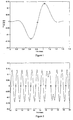
- the RDS data symbols are bi-phase symbols, wherein one symbol consists of a positive and a negative part, as it is depicted in Fig. 4.
- a time recovery loop synchronizes to the zero crossings of the RDS data symbol which is shown in Fig. 4 at approximately 0.9 msec, i.e. to the zero crossing in the middle of the data symbol. Once a zero crossing is found by the time recovery loop the next zero crossing gets searched after a time interval corresponding in length to one RDS data symbol, i.e after 0.842 msec.
- a verification is performed according to which it is determined whether a found zero crossing to which the RDS decoder synchronizes is likely to be correct or not, and the RDS decoder is synchronized to a following zero crossing which is non-linear shifted in respect to the found zero crossing in case the verification result shows that the found zero crossing is likely to be not correct.
- a non-linear shifting means that the next zero crossing is not searched after a time interval corresponding to one RDS data symbol, but around a point of time during said time interval or around a point of time which is periodic thereto in respect to the length of one RDS data symbol.
- the received RDS symbol comprising the zero crossing undergoing the verification gets sampled with at least two check samples, wherein the first check sample precedes the found zero crossing by a first predetermined distance and the second check sample succeeds the found zero crossing by a second predetermined distance, whereafter all check samples are added, the resulting sum is compared with a threshold, and in case the absolute value of the resulting sum lies above the threshold, it is determined that the found zero crossing is likely to be not correct.
- the received RDS symbol is sampled with three check samples, wherein the third check sample corresponds to the found zero crossing.
- said first determined distance equals to said second predetermined distance.
- a received RDS symbol might be sampled with at least two check samples, wherein the first check sample corresponds to the found zero crossing and the second check sample corresponds to the expected other zero crossing of the received RDS symbol, both check samples are compared, and in case the absolute value of the check sample of the found zero crossing lies above absolute value of the check sample of the other zero crossing, it is determined that said found zero crossing is likely to be not correct.
- the non-linear shift in respect to the found zero crossing according to the present invention is preferably performed by searching the next zero crossing about a time of 0.5 or n+0.5 RDS symbols after the found zero crossing, wherein n is a positive integer.
- the audible distortions during checking of the alternative frequency are minimized.
- the RDS data stream can be evaluated faster, which e. g. leads to a faster display of the station name also during the normal operation.
- An exemplary RDS data symbol is shown in Fig. 4.
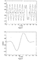
- a state of the art RDS decoder looks for the first zero crossing it finds and then synchronizes to it by looking for following zero crossings approximately after a period of time corresponding to the length of one RDS data symbol. Since the RDS data symbols are bi-phase symbols which are regularly transmitted, each of these symbols basically consists of two zero crossings. Therefore, it is possible that - depending on the transmitted data - the time recovery loop might synchronize to the wrong zero crossings.
- Fig. 6 shows such a case for a state of the art RDS decoder.
- Fig. 6 shows the same signal as depicted in Fig. 5, but the zero crossings that are used for synchronization are additionally depicted by diamonds. Since in the time interval from 10 to 16 msec the RDS signal is regular, the correct zero crossings, which are the zero crossings not indicated by diamonds, cannot be distinguished by the time recovery loop from the wrong zero crossings, which are indicated by diamonds, and to which the RDS decoder is synchronized in this example.
- the RDS decoder detects the last regular zero crossing at approximately 15.4 msec and thereafter searches the next zero crossing at 16.3 msec and obtains an amplitude value of approximately 0,1.
- One RDS data symbol later an amplitude value of approximately -0.1 is obtained, whereafter in a respective distance of one RDS data symbol an amplitude of approximately 0 is followingly obtained, since the RDS data symbols are again regularly from 17.7 msec on.
- the time recovery loop does not realize that the synchronization is wrong, since all amplitude values obtained during this periode at the found zero crossing are zero.
- the values obtained at times 16.4 msec and 17.3 msec contain high absolute values.
- the recovery loop does not realize that it is wrongly synchronized, since only two values are different from zero.
- a long time to synchronize again to the correct zero crossings is needed, since the high values of the zero crossing signal at times 16.4 msec and 17.3 msec are integrated in the loop filter of the recovery loop to an overall value of 0 which increases the problem of synchronization to the wrong zero crossing.
- the RDS decoder comprises a recovery loop which allows a non-linear operation to quickly synchronize to the correct zero crossings in case an error is detected.
- each RDS symbol is sampled with three samples, as it is shown in Fig. 1 by diamonds for the sampled values within one RDS data symbol, which RDS data symbol corresponds to that depicted in Fig. 4.
- the recovery loop in general basically operates like a state of the art recovery loop, except the fact that all three samples depicted in Fig. 1 are added and the resulting sum is compared to a threshold to verify the correctness of the found zero crossing.
- the samples depicted in Fig. 1 are a first sample approximately 1/4 RDS data symbol before the found zero crossing, the second sample approximately 1/4 RDS data symbol after the found zero crossing and the third sample at the found zero crossing.
- the sum of all these three samples is then compared with a threshold.
- the sum of all three samples is almost zero all the time due to the bi-phase structure of the RDS data symbols in case the time difference of the first to the third sample equals to that of the third to the second sample.
- the recovery loop performs a non-linear shift of the sampling time of the next expected zero crossing which is used for the synchronization, i.e. one RDS data symbol length after the found zero crossing, to the next correct zero crossing or a zero crossing succeeding the next correct zero crossing one or more RDS data symbol lengths.
- Fig. 2 depicts the zero crossings that are sampled in case the RDS decoder is synchronized correctly from the beginning of the signal, which signal is also shown in Fig. 5.
- the RDS recovery loop works similar to that of a state of the art RDS decoder.
- Fig. 3 depicts the zero crossings that are sampled by the RDS decoder according to the present invention in case the decoder is first synchronized to the wrong zero crossings for the same signal as shown in Fig. 5, i. e. shows a case comparable to that shown and described in connection with Fig. 6.
- a RDS decoder for FM broadcast which allows a fast synchronization of the RDS decoder's time recovery loop.
- the fast synchronization of the RDS time recovery loop leads to decreased distortions in the audio signal in mobile single tuner FM radios which check alternative frequencies.
- To realize the fast synchronization it is verified whether a found zero crossing to which the RDS decoder synchronizes or is synchronized is likely to be correct or not and the RDS decoder gets synchronized to a following zero crossing which is a non-linear shifted in respect to the found zero crossing in case the verification shows that the found zero crossing is likely to be not correct.
Landscapes
- Engineering & Computer Science (AREA)
- Signal Processing (AREA)
- Computer Networks & Wireless Communication (AREA)
- Circuits Of Receivers In General (AREA)
Claims (11)
- Verfahren zur Zeitsynchronisation in einem RDS Decoder durch Synchronisieren auf Nulldurchgänge von empfangenen Datensymbolen mit den Schritten:charakterisiert durch die Schritte:Überprüfen ob ein ermittelter Nulldurchgang, auf den der RDS Decoder synchronisiert oder synchronisiert wird, voraussichtlich zutreffend ist oder nicht, undSynchronisieren des RDS Decoders auf einen nachfolgenden Nulldurchgang, welcher nicht linear bezüglich des ermittelten Nulldurchgangs verschoben ist im Falle, dass die Überprüfung ergibt, dass der ermittelte Nulldurchgang voraussichtlich nicht zutreffend ist, wobei die nicht lineare Verschiebung ein Suchen nach dem nachfolgenden Nulldurchgang nicht nach einem Datensymbol entsprechenden Zeitintervall, sondern um einen Zeitpunkt während des Intervalls oder um einen hierzu um die Länge eines RDS Datensymbols periodischen Zeitpunkts einschließt, undAbtasten eines empfangenen RDS Symbols mit wenigstens zwei Prüf-Abtastwerten,Addieren aller Prüf-Abtastwerte des empfangenen RDS Symbols,Vergleichen der Ergebnissumme mit einem Schwellwert, undFestlegen, dass der ermittelte Nulldurchgang voraussichtlich nicht zutreffend ist, falls der Absolutwert der Ergebnissumme oberhalb des Schwellwerts liegt, wobeiein erster Prüf-Abtastwert der wenigstens zwei Prüf-Abtastwerte dem ermittelten Nulldurchgang um einen ersten bestimmten Abstand vorausgeht und ein zweiter Prüf-Abtastwert der wenigstens zwei Prüf-Abtastwerte dem ermittelten Nulldurchgang um einen zweiten bestimmten Abstand nachfolgt.
- Verfahren nach Anspruch 1 mit dem Schritt:Abtasten des empfangenen RDS Symbols mit drei Prüf-Abtastwerten, wobei der dritte Prüf-Abtastwert dem ermittelten Nulldurchgang entspricht.
- Verfahren nach Anspruch 1 oder 2, wobei
der erste bestimmte Abstand mit dem zweiten bestimmten Abstand übereinstimmt. - Verfahren nach Anspruch 1 mit den Schritten:Abtasten eines empfangenen RDS Symbols mit wenigstens zwei zusätzlichen Prüf-Abtastwerten, wobei ein erster zusätzlicher Prüf-Abtastwert der wenigstens zwei zusätzlichen Prüf-Abtastwerte dem ermittelten Nulldurchgang entspricht und ein zweiter zusätzlicher Prüf-Abtastwert der wenigstens zwei zusätzlichen Prüf-Abtastwerte dem erwarteten weiteren Nulldurchgang des empfangenen RDS Symbols entspricht,Vergleichen der ersten und zweiten zusätzlichen Prüf-Abtastwerte, undFestlegen, dass der ermittelte Nulldurchgang voraussichtlich nicht zutreffend ist, falls der Absolutwert des ersten zusätzlichen Prüf-Abtastwerts oberhalb des Absolutwerts des zweiten zusätzlichen Prüf-Abtastwerts liegt.
- Verfahren nach einem der Ansprüche 1 bis 4, wobei
der nachfolgende Nulldurchgang um 0,5 oder n+0.5 RDS Datensymbole nach dem ermittelten Nulldurchgang festgelegt wird, wobei n eine positive ganze Zahl ist. - RDS Decoder zum Synchronisieren auf Nulldurchgänge in RDS Datensymbolen mit:charakterisiert durcheiner Überprüfungseinrichtung, die konfiguriert und geeignet ist zum Festlegen, ob ein ermittelter Nulldurchgang, auf den der RDS Decoder synchronisiert, voraussichtlich zutreffend ist oder nicht;einer Synchronisations-Verschiebungseinrichtung, die konfiguriert und geeignet ist zum Synchronisieren des RDS Decoders auf einen nachfolgenden nicht linear bezüglich des ermittelten Nulldurchgangs verschobenen Nulldurchgang im Falle, dass die Überprüfungseinrichtung festlegt, dass der ermittelte Nulldurchgang voraussichtlich nicht zutreffend ist, wobei die nicht lineare Verschiebung ein Suchen des nachfolgenden Nulldurchgangs nicht nach einem Datensymbol entsprechenden Zeitintervall, sondern um einen Zeitpunkt während des Intervalls oder um einen hierzu um die Länge eines RDS Datensymbols periodischen Zeitpunkt einschließt, undeiner Prüf-Abtastwert-Einrichtung , die konfiguriert und geeignet ist zum Festlegen von wenigstens zwei Prüf-Abtastwerten eines empfangenen RDS Datensymbols,
einen Addierer, der konfiguriert und geeignet ist zum Addieren aller Prüf-Abtastwerte des empfangenen RDS Symbols, und
einen Komparator, der konfiguriert und geeignet ist zum Vergleichen der Ergebnissumme mit einem Schwellwert, wobei
die Überprüfungseinrichtung konfiguriert und geeignet ist zum Festlegen, dass der ermittelte Nulldurchgang voraussichtlich nicht zutreffend ist, falls der Absolutwert der Ergebnissumme oberhalb des Schwellwerts liegt, und
einen dem ermittelten Nulldurchgang um einen ersten bestimmten Abstand vorausgehenden ersten Prüf-Abtastwert der wenigstens zwei Prüf-Abtastwerte und einen dem ermittelten Nulldurchgang um einen zweiten bestimmten Abstand nachfolgenden zweiten Prüf-Abtastwert der wenigstens zwei Prüf-Abtastwerte. - RDS Decoder nach Anspruch 6, wobei
die Prüf-Abtastwert-Einrichtung konfiguriert und geeignet ist zum Festlegen von drei Prüf-Abtastwerten des empfangenen RDS Symbols, wobei der dritte Prüf-Abtastwert dem angenommenen zutreffenden Nulldurchgang entspricht. - RDS Decoder nach Anspruch 7, wobei
der erste bestimmte Abstand dem zweiten bestimmten Abstand entspricht. - RDS Decoder nach Anspruch 6, wobei
die Prüf-Abtastwert-Einrichtung konfiguriert und geeignet ist zum Festlegen von wenigstens zwei zusätzlichen Prüf-Abtastwerten, wobei ein erster Prüf-Abtastwert der wenigstens zwei zusätzlichen Prüf-Abtastwerte dem ermittelten Nulldurchgang entspricht und ein zweiter Prüf-Abtastwert der wenigstens zwei Prüf-Abtastwerte dem erwarteten weiteren Nulldurchgang des empfangenen RDS Datensymbols entspricht, und
die Überprüfungseinrichtung konfiguriert und geeignet ist zum Festlegen, dass der ermittelte Nulldurchgang voraussichtlich nicht zutreffend ist, falls der Absolutwert des ersten zusätzlichen Prüf-Abtastwerts oberhalb des Absolutwerts des zweiten zusätzlichen Prüf-Abtastwerts liegt, und der Decoder aufweist:einen Komparator, der konfiguriert und geeignet ist zum Vergleichen der ersten und zweiten zusätzlichen Prüf-Abtastwerte. - RDS Decoder nach einem der Ansprüche 6 bis 9, wobei
der nachfolgende Nulldurchgang um 0,5 oder 1,5 RDS Symbole nach dem angenommenen Nulldurchgang festgelegt wird. - Computerprogramm-Produkt mit einer Computerprogramm-Vorrichtung zum Ausführen der Verfahrensschritte nach einem der Ansprüche 1 bis 5 beim Ausführen des Computer-Programms auf einem Computer, digitalen Signalprozessor oder desgleichen.
Priority Applications (2)
| Application Number | Priority Date | Filing Date | Title |
|---|---|---|---|
| DE2001612898 DE60112898T2 (de) | 2001-05-14 | 2001-05-14 | RDS Dekoder |
| EP20010111694 EP1259023B1 (de) | 2001-05-14 | 2001-05-14 | RDS Dekoder |
Applications Claiming Priority (1)
| Application Number | Priority Date | Filing Date | Title |
|---|---|---|---|
| EP20010111694 EP1259023B1 (de) | 2001-05-14 | 2001-05-14 | RDS Dekoder |
Publications (2)
| Publication Number | Publication Date |
|---|---|
| EP1259023A1 EP1259023A1 (de) | 2002-11-20 |
| EP1259023B1 true EP1259023B1 (de) | 2005-08-24 |
Family
ID=8177424
Family Applications (1)
| Application Number | Title | Priority Date | Filing Date |
|---|---|---|---|
| EP20010111694 Expired - Lifetime EP1259023B1 (de) | 2001-05-14 | 2001-05-14 | RDS Dekoder |
Country Status (2)
| Country | Link |
|---|---|
| EP (1) | EP1259023B1 (de) |
| DE (1) | DE60112898T2 (de) |
Family Cites Families (2)
| Publication number | Priority date | Publication date | Assignee | Title |
|---|---|---|---|---|
| DE3510562A1 (de) * | 1985-03-23 | 1986-09-25 | Blaupunkt Werke Gmbh | Verfahren zur demodulation eines mit einer binaeren bitfolge phasenmodulierten eingangssignals und schaltungsanordnung zum durchfuehren des verfahrens |
| JP3244428B2 (ja) * | 1996-04-22 | 2002-01-07 | 三洋電機株式会社 | データ復調装置 |
-
2001
- 2001-05-14 EP EP20010111694 patent/EP1259023B1/de not_active Expired - Lifetime
- 2001-05-14 DE DE2001612898 patent/DE60112898T2/de not_active Expired - Fee Related
Also Published As
| Publication number | Publication date |
|---|---|
| DE60112898T2 (de) | 2007-01-04 |
| EP1259023A1 (de) | 2002-11-20 |
| DE60112898D1 (de) | 2005-09-29 |
Similar Documents
| Publication | Publication Date | Title |
|---|---|---|
| US5373536A (en) | Method of synchronizing to a signal | |
| US6731702B1 (en) | Null symbol position detecting method, null symbol position detecting apparatus, and receiver | |
| EP0939528A2 (de) | Trägersynchronisierung für DAB-Empfang | |
| JP2001524775A (ja) | 無線放送受信機 | |
| JPH01177721A (ja) | ラジオデータ受信機における受信周波数選択方法 | |
| EP1259023B1 (de) | RDS Dekoder | |
| US9531414B2 (en) | Management process of a radio service following in a receptor and corresponding receptor | |
| US6256359B1 (en) | RDS signal detection device | |
| US20090106629A1 (en) | Rds compatible receiver and rds data receiving method | |
| GB2240677A (en) | Automatic retuning in RDS receiver with means for reselecting original signal | |
| EP0701341A2 (de) | Verfahren für die Senderauswahl in einem Sendernetz und Verwendung eines solchen Verfahrens in einem Radiodatenempfänger | |
| JP2647671B2 (ja) | 受信機 | |
| EP0994586B1 (de) | Verfahren und Datenrahmenstruktur zur digitalen Nachrichtenübertragung mit quasi-nahtlosem Umschalten auf alternative Frequenzen | |
| JP2822919B2 (ja) | Rds対応受信装置及びrdsデータ受信方法 | |
| JP2558653Y2 (ja) | Rds受信機 | |
| JP2506805B2 (ja) | Rds受信機におけるデ−タ処理装置 | |
| JP3588175B2 (ja) | 波形同一識別回路 | |
| US5802067A (en) | FM multiplex broadcast receiving circuit for detecting presence or absence of multiplex information | |
| Ely et al. | Design principles for VHF/FM radio receivers using the EBU radio-data system RDS | |
| JP2596560B2 (ja) | ラジオデータシステムにおけるネットワーク局情報の選択記憶方法 | |
| JP3594323B2 (ja) | ディジタル移動通信における受信装置 | |
| JP2596559B2 (ja) | ラジオデータシステムにおける局周波数データ伝送方式の判別方法 | |
| JPH01149529A (ja) | ラジオデータシステムにおける局周波数データ伝送方式の判別方法 | |
| JPH02165717A (ja) | 車載用電子同調受信機 | |
| JP2000270035A (ja) | データ復調装置 |
Legal Events
| Date | Code | Title | Description |
|---|---|---|---|
| PUAI | Public reference made under article 153(3) epc to a published international application that has entered the european phase |
Free format text: ORIGINAL CODE: 0009012 |
|
| AK | Designated contracting states |
Kind code of ref document: A1 Designated state(s): AT BE CH CY DE DK ES FI FR GB GR IE IT LI LU MC NL PT SE TR |
|
| AX | Request for extension of the european patent |
Free format text: AL;LT;LV;MK;RO;SI |
|
| 17P | Request for examination filed |
Effective date: 20030416 |
|
| AKX | Designation fees paid |
Designated state(s): DE FR GB |
|
| 17Q | First examination report despatched |
Effective date: 20040714 |
|
| GRAP | Despatch of communication of intention to grant a patent |
Free format text: ORIGINAL CODE: EPIDOSNIGR1 |
|
| GRAS | Grant fee paid |
Free format text: ORIGINAL CODE: EPIDOSNIGR3 |
|
| GRAA | (expected) grant |
Free format text: ORIGINAL CODE: 0009210 |
|
| AK | Designated contracting states |
Kind code of ref document: B1 Designated state(s): DE FR GB |
|
| REG | Reference to a national code |
Ref country code: GB Ref legal event code: FG4D |
|
| RAP2 | Party data changed (patent owner data changed or rights of a patent transferred) |
Owner name: SONY DEUTSCHLAND GMBH |
|
| REF | Corresponds to: |
Ref document number: 60112898 Country of ref document: DE Date of ref document: 20050929 Kind code of ref document: P |
|
| ET | Fr: translation filed | ||
| PLBE | No opposition filed within time limit |
Free format text: ORIGINAL CODE: 0009261 |
|
| STAA | Information on the status of an ep patent application or granted ep patent |
Free format text: STATUS: NO OPPOSITION FILED WITHIN TIME LIMIT |
|
| 26N | No opposition filed |
Effective date: 20060526 |
|
| PGFP | Annual fee paid to national office [announced via postgrant information from national office to epo] |
Ref country code: DE Payment date: 20090511 Year of fee payment: 9 Ref country code: FR Payment date: 20090515 Year of fee payment: 9 |
|
| REG | Reference to a national code |
Ref country code: FR Ref legal event code: ST Effective date: 20110131 |
|
| PG25 | Lapsed in a contracting state [announced via postgrant information from national office to epo] |
Ref country code: DE Free format text: LAPSE BECAUSE OF NON-PAYMENT OF DUE FEES Effective date: 20101201 |
|
| PG25 | Lapsed in a contracting state [announced via postgrant information from national office to epo] |
Ref country code: FR Free format text: LAPSE BECAUSE OF NON-PAYMENT OF DUE FEES Effective date: 20100531 |
|
| PGFP | Annual fee paid to national office [announced via postgrant information from national office to epo] |
Ref country code: GB Payment date: 20110520 Year of fee payment: 11 |
|
| GBPC | Gb: european patent ceased through non-payment of renewal fee |
Effective date: 20120514 |
|
| PG25 | Lapsed in a contracting state [announced via postgrant information from national office to epo] |
Ref country code: GB Free format text: LAPSE BECAUSE OF NON-PAYMENT OF DUE FEES Effective date: 20120514 |