EP1259335B1 - Systeme intelligent de machine outil - Google Patents
Systeme intelligent de machine outil Download PDFInfo
- Publication number
- EP1259335B1 EP1259335B1 EP01914563A EP01914563A EP1259335B1 EP 1259335 B1 EP1259335 B1 EP 1259335B1 EP 01914563 A EP01914563 A EP 01914563A EP 01914563 A EP01914563 A EP 01914563A EP 1259335 B1 EP1259335 B1 EP 1259335B1
- Authority
- EP
- European Patent Office
- Prior art keywords
- tool
- electronic device
- data
- machine tool
- operating
- Prior art date
- Legal status (The legal status is an assumption and is not a legal conclusion. Google has not performed a legal analysis and makes no representation as to the accuracy of the status listed.)
- Expired - Lifetime
Links
Images




Classifications
-
- G—PHYSICS
- G05—CONTROLLING; REGULATING
- G05B—CONTROL OR REGULATING SYSTEMS IN GENERAL; FUNCTIONAL ELEMENTS OF SUCH SYSTEMS; MONITORING OR TESTING ARRANGEMENTS FOR SUCH SYSTEMS OR ELEMENTS
- G05B19/00—Program-control systems
- G05B19/02—Program-control systems electric
- G05B19/18—Numerical control [NC], i.e. automatically operating machines, in particular machine tools, e.g. in a manufacturing environment, so as to execute positioning, movement or co-ordinated operations by means of program data in numerical form
- G05B19/406—Numerical control [NC], i.e. automatically operating machines, in particular machine tools, e.g. in a manufacturing environment, so as to execute positioning, movement or co-ordinated operations by means of program data in numerical form characterised by monitoring or safety
- G05B19/4065—Monitoring tool breakage, life or condition
-
- B—PERFORMING OPERATIONS; TRANSPORTING
- B21—MECHANICAL METAL-WORKING WITHOUT ESSENTIALLY REMOVING MATERIAL; PUNCHING METAL
- B21C—MANUFACTURE OF METAL SHEETS, WIRE, RODS, TUBES, PROFILES OR LIKE SEMI-MANUFACTURED PRODUCTS OTHERWISE THAN BY ROLLING; AUXILIARY OPERATIONS USED IN CONNECTION WITH METAL-WORKING WITHOUT ESSENTIALLY REMOVING MATERIAL
- B21C51/00—Measuring, gauging, indicating, counting, or marking devices specially adapted for use in the production or manipulation of material in accordance with subclasses B21B - B21F
-
- B—PERFORMING OPERATIONS; TRANSPORTING
- B21—MECHANICAL METAL-WORKING WITHOUT ESSENTIALLY REMOVING MATERIAL; PUNCHING METAL
- B21J—FORGING; HAMMERING; PRESSING METAL; RIVETING; FORGE FURNACES
- B21J13/00—Details of machines for forging, pressing, or hammering
- B21J13/08—Accessories for handling work or tools
- B21J13/085—Accessories for handling work or tools handling of tools
-
- B—PERFORMING OPERATIONS; TRANSPORTING
- B23—MACHINE TOOLS; METAL-WORKING NOT OTHERWISE PROVIDED FOR
- B23B—TURNING; BORING
- B23B41/00—Boring or drilling machines or devices specially adapted for particular work; Accessories specially adapted therefor
- B23B41/02—Boring or drilling machines or devices specially adapted for particular work; Accessories specially adapted therefor for boring deep holes; Trepanning, e.g. of gun or rifle barrels
-
- B—PERFORMING OPERATIONS; TRANSPORTING
- B23—MACHINE TOOLS; METAL-WORKING NOT OTHERWISE PROVIDED FOR
- B23Q—DETAILS, COMPONENTS, OR ACCESSORIES FOR MACHINE TOOLS, e.g. ARRANGEMENTS FOR COPYING OR CONTROLLING; MACHINE TOOLS IN GENERAL CHARACTERISED BY THE CONSTRUCTION OF PARTICULAR DETAILS OR COMPONENTS; COMBINATIONS OR ASSOCIATIONS OF METAL-WORKING MACHINES, NOT DIRECTED TO A PARTICULAR RESULT
- B23Q17/00—Arrangements for observing, indicating or measuring on machine tools
- B23Q17/09—Arrangements for observing, indicating or measuring on machine tools for indicating or measuring cutting pressure or for determining cutting-tool condition, e.g. cutting ability, load on tool
-
- B—PERFORMING OPERATIONS; TRANSPORTING
- B23—MACHINE TOOLS; METAL-WORKING NOT OTHERWISE PROVIDED FOR
- B23Q—DETAILS, COMPONENTS, OR ACCESSORIES FOR MACHINE TOOLS, e.g. ARRANGEMENTS FOR COPYING OR CONTROLLING; MACHINE TOOLS IN GENERAL CHARACTERISED BY THE CONSTRUCTION OF PARTICULAR DETAILS OR COMPONENTS; COMBINATIONS OR ASSOCIATIONS OF METAL-WORKING MACHINES, NOT DIRECTED TO A PARTICULAR RESULT
- B23Q3/00—Devices holding, supporting, or positioning work or tools, of a kind normally removable from the machine
- B23Q3/155—Arrangements for automatic insertion or removal of tools, e.g. combined with manual handling
- B23Q3/1552—Arrangements for automatic insertion or removal of tools, e.g. combined with manual handling parts of devices for automatically inserting or removing tools
- B23Q3/15546—Devices for recognizing tools in a storage device, e.g. coding devices
-
- B—PERFORMING OPERATIONS; TRANSPORTING
- B30—PRESSES
- B30B—PRESSES IN GENERAL
- B30B15/00—Details of, or accessories for, presses; Auxiliary measures in connection with pressing
- B30B15/26—Program-control arrangements
-
- G—PHYSICS
- G05—CONTROLLING; REGULATING
- G05B—CONTROL OR REGULATING SYSTEMS IN GENERAL; FUNCTIONAL ELEMENTS OF SUCH SYSTEMS; MONITORING OR TESTING ARRANGEMENTS FOR SUCH SYSTEMS OR ELEMENTS
- G05B2219/00—Program-control systems
- G05B2219/30—Nc systems
- G05B2219/37—Measurements
- G05B2219/37249—Correction coefficient of life time as function of kind of machining
-
- G—PHYSICS
- G05—CONTROLLING; REGULATING
- G05B—CONTROL OR REGULATING SYSTEMS IN GENERAL; FUNCTIONAL ELEMENTS OF SUCH SYSTEMS; MONITORING OR TESTING ARRANGEMENTS FOR SUCH SYSTEMS OR ELEMENTS
- G05B2219/00—Program-control systems
- G05B2219/30—Nc systems
- G05B2219/37—Measurements
- G05B2219/37252—Life of tool, service life, decay, wear estimation
-
- G—PHYSICS
- G05—CONTROLLING; REGULATING
- G05B—CONTROL OR REGULATING SYSTEMS IN GENERAL; FUNCTIONAL ELEMENTS OF SUCH SYSTEMS; MONITORING OR TESTING ARRANGEMENTS FOR SUCH SYSTEMS OR ELEMENTS
- G05B2219/00—Program-control systems
- G05B2219/30—Nc systems
- G05B2219/45—Nc applications
- G05B2219/45204—Die, mould making
-
- G—PHYSICS
- G05—CONTROLLING; REGULATING
- G05B—CONTROL OR REGULATING SYSTEMS IN GENERAL; FUNCTIONAL ELEMENTS OF SUCH SYSTEMS; MONITORING OR TESTING ARRANGEMENTS FOR SUCH SYSTEMS OR ELEMENTS
- G05B2219/00—Program-control systems
- G05B2219/30—Nc systems
- G05B2219/45—Nc applications
- G05B2219/45215—Thread cutting
-
- G—PHYSICS
- G05—CONTROLLING; REGULATING
- G05B—CONTROL OR REGULATING SYSTEMS IN GENERAL; FUNCTIONAL ELEMENTS OF SUCH SYSTEMS; MONITORING OR TESTING ARRANGEMENTS FOR SUCH SYSTEMS OR ELEMENTS
- G05B2219/00—Program-control systems
- G05B2219/30—Nc systems
- G05B2219/49—Nc machine tool, till multiple
- G05B2219/49305—Store, memory on tool with control and maintenance data
-
- Y—GENERAL TAGGING OF NEW TECHNOLOGICAL DEVELOPMENTS; GENERAL TAGGING OF CROSS-SECTIONAL TECHNOLOGIES SPANNING OVER SEVERAL SECTIONS OF THE IPC; TECHNICAL SUBJECTS COVERED BY FORMER USPC CROSS-REFERENCE ART COLLECTIONS [XRACs] AND DIGESTS
- Y02—TECHNOLOGIES OR APPLICATIONS FOR MITIGATION OR ADAPTATION AGAINST CLIMATE CHANGE
- Y02P—CLIMATE CHANGE MITIGATION TECHNOLOGIES IN THE PRODUCTION OR PROCESSING OF GOODS
- Y02P90/00—Enabling technologies with a potential contribution to greenhouse gas [GHG] emissions mitigation
- Y02P90/02—Total factory control, e.g. smart factories, flexible manufacturing systems [FMS] or integrated manufacturing systems [IMS]
Definitions
- This invention relates firstly to a machine tool system comprising a tool for cold forming a workpiece over an operating cycle, the tool having an electronic device fixedly mounted thereto, the electronic device having means for storing data including identification data for the tool and operating data for the tool, the operating data for the tool including tool life remaining for the tool, a sensor device which senses each operating cycle of the tool, and at least one interface device in communication with the electronic device and the sensor device.
- This invention further relates to a method of monitoring the life cycle of a cold forming tool in a cold forming system, the tool having an electronic device fixedly mounted thereto.
- thread rolling dies to which the invention relates, workpieces are transformed into finished screws by a rolling process as the workpieces pass between a pair of elongated generally planar dies.
- One of the dies is stationary, and the other die is displaced relative to the other to produce a surface material flow on the workpiece to thereby form a continuous helical thread path on the screw.
- a shorter die of a pair of dies is held in stationary relationship while the longer die is moved in a direction generally parallel to a longitudinal reference plane.
- the axis of rotation of the body of the workpiece travels longitudinally as the workpiece rolls between the pair of dies.
- the diameter of the finished thread is controlled by the diameter of the workpiece and the distance between the dies at the finished end of the stroke.
- the dies are configured so that as the workpiece rolls across the dies, the desired threading is formed on the workpiece. Thread rolling is also accomplished using cylindrical or planetary dies and machines and this invention is applicable to all known configurations.
- manufacturers must maintain a cost effective manufacturing environment and must be responsive to customer requests. These two goals can often be in conflict. For example, costs may be reduced by maintaining low inventories of raw materials, finished products, and tooling. However, if such inventories are too low, the manufacturer may be unable to promptly respond to a customer order. Manufacturers typically strike a balance where they maintain some minimum inventory of raw materials and/or finished product such that a hypothetical order may be filled within an acceptable time period. Such manufacturers also monitor their tooling to ensure that new tooling is received just as the old tooling reaches the end of its effective lifetime.
- Each set of tools has an effective lifetime which is defined by a maximum number of operating cycles which may be performed before the accumulated wear precludes further use.
- the rate of tool wear is proportional to the material hardness of the workpieces, where the rate of die wear increases as the material hardness increases. Consequently, the effective lifetime of a die set which is used to form threads on workpieces composed of relatively hard stainless steel is lower than the effective lifetime of an identical die set which is used to form threads on workpieces composed of relatively soft carbon steel.
- a machine tool system comprising a tool for cold forming a workpiece over an operating cycle, the tool having an electronic device fixedly mounted thereto, the electronic device having means for storing data including identification data for the tool and operating data for the tool, the operating data for the tool including tool life remaining for the tool, a sensor device which senses each operating cycle of the tool, and at least one interface device in communication with the electronic device and the sensor device is, according to the invention, characterized in that a microprocessor device is provided and is in communication with the interface device, the microprocessor device being configured to a) receive operating cycle data from the sensor device; b) determine the expected number of operating cycles over the lifetime of the tool; c) access the identification data and the operating cycle data stored in the electronic device; d) calculate the number of operating cycles that the tool has been used from the operating cycle data; e) subtract the number of operating cycles that the tool has been used from the expected number of operating cycles over the lifetime of the tool to determine the remaining lifetime of the tool; and f) store the remaining lifetime of the tool in the
- the electronic device such as a microchip is encased in sealant material within a recess in an exterior surface of the tool.
- the electronic device may have an antenna extending within the sealant material or an electrical or fiber optic lead extending through the sealant material to the surface of the tool.
- the machine tool system interface device generally includes a process monitoring system having a key pad, a monitor, and a microprocessor.
- the process monitoring system may include a temperature sensor for measuring the temperature of the tool and/or a flow detector for monitoring the flow of coolant to the tool.
- the interface device also generally includes a portable electronic reader.
- the portable electronic reader includes a first data transmission interface for sending and receiving signals to the electronic device, memory for storing the signals received from the electronic device, and a second data transmission interface for transmitting the stored signals to the process monitoring system.
- the portable electronic reader may also include a display for viewing the signals received from the electronic device.
- the machine tool system provides a means for monitoring the life cycle of the tool.
- Each cold forming tool has a lifetime which can be expressed as the number of operating cycles which can be expected from the tool before such tool no longer operates properly or efficiently.
- the sensor device senses each operating cycle of the tool and transmits operating cycle data to the electronic device, where such operating cycle data is stored and processed.
- the identification data and the operating cycle data stored in the electronic device is accessed by the monitoring system or the portable electronic reader and is used to calculate the number of operating cycles that the tool has been used. Subtracting the number of operating cycles that the tool has been used from the expected number of operating cycles over the lifetime of the tool provides a measure of the remaining lifetime of the tool.
- a stationary die 10 and a moveable die 12 are employed to roll a thread on a workpiece to produce a finished screw by a reciprocating flat die method.
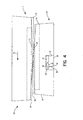
- the reciprocating moveable die 12 moves relative to the stationary die 10 in the direction of the arrows 14 in Figures 2 and 4 to define a rolling cycle.
- a thread is formed on the workpiece.
- the dies 10, 12 each have opposing faces 20, 22 configured with ridges and grooves which form the threads and define, for example, the pitch, major diameter, minor diameter and thread type of the finished screw.
- the dies 10, 12 during each rolling cycle cooperatively gradually penetrate the workpiece to form the finished screw.
- the dies 10, 12 are configured so that the least amount of rolling work as possible is done in the dwell section to maximize the life of the die.
- a starter finger engages the workpiece blank to ensure that the moving die 12 picks up the blank and starts the rolling process.
- the threads are deep and sharp.
- the dwell sections 26, 28 the threads are flat and shallower. The starting end threads are sharp for easier penetration as the screw starts to roll and get progressively wider along the die length until they ultimately reach width and depth equal to the desired finished thread form.
- the dies 10, 12 are aligned or "matched" to produce the proper optimum thread continuum.
- the final die form is termed the dwell section 26, 28 and extends along the die 10, 12 for distance long enough to properly dimension the screw.
- the thread and tip are fully developed just prior to parting the dies.
- An ideal pressure cycle may be calculated and compared to the observed pressure cycle of an operating thread rolling system as a means of monitoring its performance.
- the IMPAX/SK 3000 TM process monitoring system monitors and displays the rolling pressure force over each rolling cycle of the thread rolling system. The ideal pressure cycle is displayed simultaneously so that the operator is provided with real-time information on deviation from optimum system operating conditions.
- the IMPAX/SK 3000 TM process monitoring system utilizes a piezo-electric sensing device mounted in a die adjusting block to sense the pressure exerted on the workpiece by the dies.
- Other conventional thread rolling system process monitoring systems may utilize other sensors and locate these sensors in the die block, the frame, or the yoke.
- a persistent deviation between the measured pressure cycle and the ideal pressure cycle generally indicates that the thread rolling system setup is improper. When this occurs, the operator may adjust the thread rolling system setup to minimize or eliminate such deviations and thereby optimize the system performance. A deviation may indicate that a faulty screw was produced during the rolling cycle in which the deviation was observed. When this occurs, the operator may check the output of the thread rolling system to verify the quality of the product.
- a first embodiment 30 of a machine tool system in accordance with the invention includes a cold forming tool 32, such as a pair of flat thread rolling dies 10, 12, having an embedded electronic device such as a microchip 34.
- the microchip 34 is positioned in a recess 36 in the stationary die 10 and is mounted within the recess 36 by a sealant material 38, such as potting compound or epoxy, which seals the recess 36 against infiltration by particulate matter and liquids.
- An antenna 40 extending from the microchip 34 may also be disposed within the sealant material 38.
- an electrical or fiber optic lead 42 may extend from the microchip 34, through the sealant material 38, to at least the surface of the stationary die 10.
- the microchip 34 includes at least a memory portion 44 and a data transmission portion 46.
- the memory portion 44 has sufficient storage capacity to store tool identification and design data which does not change over the lifetime of the tool and tool operating data which is updated as the tool is used in the manufacturing process.
- Permanent tool data for a thread rolling die set may include the customer part number, the manufacturer part number, manufacturing information, set-up information such as an optimum rolling force curve, and the effective lifetime expressed as a number of rolling cycles.
- Operating data for a thread rolling die set 10, 12 may include the date/time of each set-up, the date/time of each run, the number of rolling cycles in each run, the number of set-up adjustments in each run, abnormal force incidents, wear pattern documentation by run, and the tool life remaining expressed as a number of rolling cycles.
- the microchip 34 stores the permanent data and the operating data and communicates this data when queried by an electronic reader.
- the data transmission portion 46 includes all circuit components and/or software that is required to transmit and receive the operating data. It should be appreciated that any electronic device having at least the memory and data transmission portions 44, 46 described above and which is small enough and rugged enough to be embedded on a cold forming tool 32 may be used in the present invention.
- the cold forming machine 48 in which the cold forming tool 32 is mounted includes a process monitoring system 50 having an electronic reader 52, which communicates with the microchip 34 embedded in the cold forming tool 32. Such communication may be by microwave, Rf, infrared, or other common radiation of the electromagnetic spectrum.
- the process monitoring system 50 also includes sensors 54 for detecting various operating parameters of the cold forming tool 32.
- the sensors 54 may include a sensor, such as a piezo electric sensor capable of sensing the pressure cycle, for detecting operation of the cold forming tool, a temperature sensor for measuring the temperature of the cold forming tool, or a flow detector for monitoring coolant flow to the cold forming tool.
- the process monitoring system 50 may also include a key pad 56 for inputting data, a monitor 58 for displaying process information, such as the pressure cycle and a data output 60 to a master scheduler system or a machine control system.
- the process monitoring system sensors 54 and/or the process monitoring system key pad 56 are utilized to input all the parameters which are recorded in the microchip 34.
- a microprocessor 62 in the process monitoring system 50 performs any calculations which are necessary to convert the input signals or transform the sensed or inputted data into the form required for storage in the microchip 34. For example, microprocessor 62 calculates the remaining effective lifetime of the cold forming tool 32 based on the output of the sensor 54 which detects operation of the cold forming tool 32 and the expected life data and prior use data stored in microchip 34.
- the data/query signal received by the data transmission portion 46 of the microchip 34 provides the power required by the microchip 34 to record the data or respond to the query and therefore an external power source is not required. If the data/query signal does not provide sufficient power, an external power source may be used. A battery mounted in the recess 36 may be used as the external power source. Machine generated vibration power may be utilized as well. Alternatively, a data/power connection may be provided between the process monitoring system 50 and microchip via electrical lead 42. If an external power source is utilized, the microchip 34 may be used to perform more power intensive functions. For example, the calculations performed by microprocessor 62 could be performed by microchip 34.
- the machine tool system also includes a portable, hand-held electronic reader 64.
- the hand-held electronic reader 64 includes a communications portion 66, comprising the circuit components and/or software which are required to send and receive data and query signals, a data transmission interface 68 for sending and receiving signals to microchip 34, and a data transmission interface 70 for transmitting the stored data to the central control system or some other central monitoring system.
- the hand-held electronic reader 64 also includes memory 72 for storing the data received in response to the query and may include a display 74 for viewing the data received from microchip 34.
- the hand-held electronic reader 64 provides flexibility to the subject machine tool system 30, 30'. For example, if the display 58 of the process monitoring system 50 is at a location which is remote from the cold forming tool 32, the hand-held electronic reader 64 allows the operator to query and view the stored data while he is at the cold forming tool 32.
- the first die set 10, 12 (which had been used to produce the first type of screw) is removed from the cold forming machine, a second die set 10, 12 designed for producing the second type of screw is removed from the tool crib and mounted in the cold forming machine 48, and the cold forming machine 48 commences the production run of the second type of screw. If the first die set 10, 12 has not reached the end of its effective lifetime, it is placed in the tool crib for use in the next production run of the first type of screw.
- the tool crib generally contains new die sets and used die sets.
- a manufacturer can easily know which cold forming tools 32 are installed in the cold forming machines 48 and which cold forming tools 32 are stored in the tool crib.
- the hand-held electronic reader 64 and imbedded microchip 34 provide a means for easily conducting and maintaining an accurate inventory of the manufacturers' cold forming tools 32. More importantly, an inventory conducted with the subject the hand-held electronic reader 64 and imbedded microchip 34 includes easily accessible and up to the minute information on the operating history of each of the cold forming tools 32 and the tool remaining life. To conduct the inventory, the user merely passes the hand-held electronic reader 64 by each cold forming tool 32. During each pass, the reader 64 queries the tool 32, the tool 32 transmits data stored in the microchip 34, and the transmitted data is stored in memory 72.
- the stored data is downloaded to the central computer periodically during the inventory or at the end of the inventory, and the central computer compiles an inventory list.
- the data query may be customized depending on the needs of a particular inventory. It should be appreciated that the accuracy and ease of use of this method of inventory is dependent on the microchip 34 which is embedded in and inseparable from each cold forming tool 32.
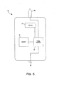
- the embodiment 30' illustrated in Figures 3 and 4 is very similar to the first embodiment 30 with the primary exception that a sensing device 76, such as a piezo electric device, is mounted in the recess 36 and in communication with the microchip 34. Consequently, the sensing device signal may be received directly by the microchip 34 instead of by way of the microprocessor 62' in the process monitoring system.
- the sensing device signal provides the power required by the microchip 34 to record the data.
- an external power source such as a battery or an electrical connection with the microprocessor may be used.
- the microchip 34 may perform any required calculations and data conversion if an external power source is utilized. Otherwise, the process monitoring system microprocessor 62' performs the required calculations and data conversion.
- the process monitoring system includes an electronic reader 52', additional sensors, a key pad 56', a monitor 58', and a data output 60' to a master scheduler system or a machine control system.
- Figures 6a through 6d show the basic sequence of actions in a standard type solid die, double stroke heading machine.
- wire 78 is shown being fed through the cut off die 80 until it reaches the wire stop 82. By adjusting the location of this stop 82, the operator determines the length of the blank 86.
- the cutoff knife 84 has already cut the blank 86 from the coil and carried it (the blank) to the heading die 88.
- the knife stroke is set to stop when the blank 86 is centered on the heading die 88.
- the first punch 90 comes forward for the first blow.
- the first and second punches 90, 92 are both carried on the ram or gate 94 (both terms are commonly used).
- the first punch 90 begins its forward stroke, it pushes the blank 86 into the heading die 88, right up against the knockout pin 96 (if no extrusion is being done).
- the blank 86 is subjected to the full force of the first punch 90, and begins to flow into its new shape.
- the extrusion, if any, is done, and the head has been upset into the cone shape, ready for final shaping.
- the cam-operated mechanism shifts the punches 90, 92 after the first blow, so that the second punch 92 is aligned with the heading die 88.
- the gate 94 comes forward again, the second or finish blow, is struck, and the gate 94 withdraws.
- the punches 90, 92 are now shifted so that the first, or cone punch 90, is again in position for the new blank.
- the knockout pin 96 comes forward all the way to the face of the die 88, forcing the finished part 98 out ahead of it.
- the finished part 98 is ejected and falls into a collection bin 100.
- the cutoff knife 84 is already starting to move a new blank into position, ready to begin the cycle all over again.
- a sensor 102, 102' and a microchip 104, 104' are mounted in a recess in each of the gate 94 and heading die 88.
- the sensors 102, 102' detect each operation of the cold heading tool and transmit a signal to a process monitoring system for use by the system and for storage in the microchip 104, 104'.
- gundrilling is a metal removal process utilizing a drilling machine 108, a high pressure coolant system 110, and a single or a two flute gundrill 112.
- the gundrilling process is a controlled operation which offers size, location, finish, and straightness accuracy where critical tolerances are important. Added benefits are scrap reduction, burr-free holes, bottom forming, and blind holes, as well as entry with surfaces other than 90 degrees. Repeatability makes this application feasible on numerically controlled equipment.
- gundrills 112 and coolant systems 110 are easily integrated with CNC machining centers, lathes, and milling machines, providing users with all the benefits of the process for a relatively small investment. Incorporating gundrills 112 on other types of machinery often requires a short (1 to 2 diameters deep) starter hole to be used in place of the gundrilling machine's starter bushing 116. The gundrill tip 114 is then fed Into the predrilled hole before engaging the spindle.
- the gundrill 112 is a simple, basic tool with three essential parts: the tip 114, the shank 118, and the driver 120. These parts are brazed together into one correctly aligned unit.
- the tip 114 is the most critical of the three elements.
- the tip 114 cuts the hole and maintains precision as it pilots the drill through the part, producing precision holes in one pass.
- the point or nosegrind has two basic angles that may be varied for optimum results depending on the material to be drilled. These angles must balance the cutting forces, distributing them to the tip's bearing pads to keep the drill concentric.
- the tip 114 is slightly larger in diameter than the shank, thus enabling the shank 118 to rotate freely without contacting the hole wall.
- Through the tip 114 is an oil hole which lines up with the shank's oil channel to facilitate correct flow of coolant at high pressures to the cutting edge.
- a sensor 122 and a microchip 124 are mounted in a recess 126 in the gundrill 112.
- the sensor 122 detects each operation of the gundrill 112 and transmits a signal to a process monitoring system for use by the system and for storage in the microchip 124.
- sensors 128, 130, 132 may also be located in other components of the gundrilling system, as shown in Figure 7.
- Sensors 128 in the coolant system 110 may be provided to sense coolant flow and/or temperature.
Landscapes
- Engineering & Computer Science (AREA)
- Mechanical Engineering (AREA)
- Human Computer Interaction (AREA)
- Manufacturing & Machinery (AREA)
- Physics & Mathematics (AREA)
- General Physics & Mathematics (AREA)
- Automation & Control Theory (AREA)
- General Factory Administration (AREA)
- Machine Tool Sensing Apparatuses (AREA)
- Auxiliary Devices For Machine Tools (AREA)
- Apparatuses For Bulk Treatment Of Fruits And Vegetables And Apparatuses For Preparing Feeds (AREA)
- Automatic Tool Replacement In Machine Tools (AREA)
Claims (30)
- Système de machine-outil (30, 30') comprenant:un outil (32) pour former à froid une pièce d'usinage au cours d'un cycle de travail, l'outil (32) ayant un dispositif électronique (34) monté en position fixe sur lui, le dispositif électronique (34) ayant un moyen de conservation de données (44), comprenant des données d'identification pour l'outil (32) et des données de travail pour l'outil (32), les données de travail pour l'outil (32) comprenant la durée de vie résiduelle de l'outil (32);un dispositif de capteur (54) qui détecte chaque cycle de travail de l'outil (32); etau moins un dispositif d'interface en communication avec le dispositif électronique (34) et le dispositif de capteur (54);caractérisé en cequ'un dispositif à microprocesseur (62, 62') est prévu et il est en communication avec le dispositif d'interface, le dispositif à microprocesseur (62, 62') étant configuré pour:recevoir des données sur le cycle de travail à partir du dispositif de capteur (54);déterminer le nombre attendu de cycles de travail au cours de la durée de vie de l'outil (32);accéder aux données d'identification et aux données sur le cycle de travail conservées dans le dispositif électronique (34);calculer le nombre de cycles de travail que l'outil (32) a exécutés à partir des données sur le cycle de travail;soustraire le nombre de cycles de travail que l'outil (32) a exécutés du nombre attendu déterminé de cycles de travail au cours de la durée de vie de l'outil (32) afin de déterminer la durée de vie résiduelle de l'outil (32); etconserver la durée de vie résiduelle de l'outil (32) dans le dispositif électronique (34).
- Système de machine-outil selon la revendication 1 comprenant en outre un matériau d'étanchéité (38), l'outil (32) ayant une surface extérieure et définissant un renfoncement (36) s'étendant à partir de la surface, le dispositif électronique (34) étant disposé dans le renfoncement (36) et enchâssé par le matériau d'étanchéité (38), le dispositif électronique (34) ayant une antenne (40) s'étendant dans le matériau d'étanchéité (38).
- Système de machine-outil selon la revendication 1 comprenant en outre un matériau d'étanchéité (38), l'outil (32) ayant une surface extérieure et définissant un renfoncement (36) s'étendant à partir de la surface, le dispositif électronique (34) étant disposé dans le renfoncement (36) et enchâssé par le matériau d'étanchéité (38), le dispositif électronique (34) ayant une broche à fibre optique (42) s'étendant à travers le matériau d'étanchéité (38) jusqu'à au moins la surface de l'outil (38).
- Système de machine-outil selon la revendication 1, dans lequel l'au moins un dispositif d'interface comprend un système de surveillance du processus (50) ayant un clavier (56), un écran (58) et un microprocesseur (62).
- Système de machine-outil selon la revendication 4, dans lequel le système de surveillance du processus (50) comprend également un capteur de température afin de mesurer la température de l'outil (32).
- Système de machine-outil selon la revendication 4, dans lequel l'outil (32) a également un système de refroidissement transportant un flux de réfrigérant à travers l'outil (32) et le système de surveillance du processus (50) comprend également un détecteur de flux afin de surveiller le flux du réfrigérant.
- Système de machine-outil selon la revendication 4, dans lequel l'au moins un dispositif d'interface comprend également un lecteur électronique portable (64).
- Système de machine-outil selon la revendication 7, dans lequel le lecteur électronique portable (64) comprend une première interface de transmission de données (68) pour envoyer et recevoir des signaux à destination et en provenance du dispositif électronique (34), une mémoire (72) pour conserver les signaux reçus depuis le dispositif électronique (34) et une deuxième interface de transmission de données (70) pour transmettre les signaux conservés au système de surveillance du processus (50).
- Système de machine-outil selon la revendication 8, dans lequel le lecteur électronique portable (64) comprend également un affichage (74) pour visualiser les signaux reçus depuis le dispositif électronique (34).
- Système de machine-outil selon la revendication 1, dans lequel le dispositif électronique (34) et le dispositif d'interface ont chacun une partie de communication (46, 52), la partie de communication (52) du dispositif d'interface comprenant un moyen pour transmettre un signal de données/d'interrogation et la partie de communication (46) du dispositif électronique (34) ayant un moyen pour recevoir le signal de données/d'interrogation et alimenter le moyen de conservation de données (44) avec le signal de données/d'interrogation.
- Système de machine-outil selon la revendication 1, comprenant en outre une source d'alimentation montée sur l'outil (32).
- Système de machine-outil selon la revendication 1, dans lequel l'outil (32) comprend un poinçon (90, 92), une matrice (88) et un marteau (94), le dispositif de capteur (54) comprend des premier et deuxième capteurs (102, 102'), et le dispositif électronique (34) comprend un premier microcircuit (104'), la matrice (88) et le marteau (94) définissant chacun un renfoncement, le premier capteur (102') et le premier microcircuit (104') étant montés dans le renfoncement de la matrice (88) et le deuxième capteur (102') étant monté dans le renfoncement du marteau (94).
- Système de machine-outil selon la revendication 12, dans lequel le dispositif électronique (34) comprend en outre un deuxième microcircuit (104) monté dans le renfoncement du marteau (94).
- Système de machine-outil selon la revendication 1, dans lequel l'outil (32) est un foret à canon (112) définissant un renfoncement (126), le capteur (122) étant monté dans le renfoncement (126) du foret à canon (112).
- Système de machine-outil selon la revendication 14, dans lequel le dispositif électronique (124) est monté dans le renfoncement (126) du foret à canon (112).
- Système de machine-outil selon la revendication 1, dans lequel les données d'identification de l'outil (32) sont sélectionnées parmi le numéro de pièce du client, le numéro de pièce du fabricant, une information de fabrication, une information de montage, la durée de vie effective ou toute combinaison de ces données.
- Système de machine-outil selon la revendication 16, dans lequel l'information de montage comprend une courbe de force de laminage optimale.
- Système de machine-outil selon la revendication 16, dans lequel la durée de vie effective est un nombre prédéterminé de cycles de laminage.
- Système de machine-outil selon la revendication 1, dans lequel l'outil est une matrice de laminage et les données de travail sur l'outil (32) comprennent des paramètres sélectionnés parmi la date/l'heure de chaque montage, la date/l'heure de chaque passe, le nombre de cycles de laminage exécutés dans chaque passe, le nombre d'ajustements de montage exécutés dans chaque passe, les incidents de force anormale, le schéma d'usure par passe ou toute combinaison de ces données.
- Système de machine-outil selon la revendication 1, dans lequel l'outil est une matrice de laminage et la durée de vie résiduelle de l'outil est calculée en soustrayant le nombre de cycles de laminage exécutés par l'outil (32) d'un nombre prédéterminé de cycles de laminage.
- Système de machine-outil selon la revendication 10, dans lequel aucune autre source d'alimentation n'est reliée au dispositif électronique (34).
- Système de machine-outil selon la revendication 11, dans lequel la source d'alimentation est une pile.
- Système de machine-outil selon la revendication 11, dans lequel le dispositif de capteur est un dispositif piézo-électrique (54), ledit dispositif piézo-électrique (54) émettant un signal indiquant le cycle de travail de l'outil (32), ledit signal alimentant le moyen de conservation de données (44), ce par quoi ledit dispositif piézo-électrique (54) est la source d'alimentation.
- Procédé de surveillance du cycle de vie d'un outil de formage à froid (32) dans un système de formage à froid (30, 30'), l'outil (32) ayant un dispositif électronique (34) monté en position fixe sur lui, le procédé comprenant les étapes consistant à:conserver des données d'identification pour l'outil (32) dans le dispositif électronique (34);détecter chaque cycle de travail de l'outil (32) avec un dispositif de capteur de cycle de travail (54) et transmettre des données sur le cycle de travail à partir du dispositif de capteur de signal de travail (54);recevoir et conserver les données sur le cycle de travail dans le dispositif électronique (34); déterminer le nombre attendu de cycles de travail au cours de la durée de vie de l'outil (32);accéder aux données d'identification et aux données sur le cycle de travail conservées dans le dispositif électronique (34);calculer le nombre de cycles de travail que l'outil (32) a exécutés à partir des données sur le cycle de travail;soustraire le nombre de cycles de travail que l'outil (32) a exécutés du nombre attendu déterminé de cycles de travail au cours de la durée de vie de l'outil (32) afin de déterminer la durée de vie résiduelle de l'outil (32); etconserver la durée de vie résiduelle de l'outil (32) dans le dispositif électronique (34).
- Procédé selon la revendication 24, dans lequel le système de formage à froid (30, 30') a en plus un système de surveillance du processus (50), le procédé comprenant en outre les étapes consistant à:recevoir les données sur le cycle de travail dans le système de surveillance du processus (50); ettransmettre les données sur le cycle de travail depuis le système de surveillance du processus (50) vers le dispositif électronique (34).
- Procédé selon la revendication 25, dans lequel le système de formage à froid (30, 30') a en plus un capteur de température, le procédé comprenant en outre les étapes consistant à;détecter la température de l'outil (32); ettransmettre un signal correspondant à la température détectée de l'outil (32) au système de surveillance du processus (50).
- Procédé selon la revendication 25, comprenant en outre les étapes consistant à:accéder aux données d'identification et aux données sur le cycle de travail conservées dans le dispositif électronique (34) avec le système de surveillance du processus (50); etafficher les données d'identification et les données sur le cycle de travail au niveau du système de surveillance du processus (50).
- Procédé selon la revendication 24, comprenant en outre l'étape consistant à accéder aux données d'identification et aux données sur le cycle de travail conservées dans le dispositif électronique (34) avec un lecteur portable (64).
- Procédé selon la revendication 28, comprenant en outre l'étape consistant à enregistrer les données d'identification et les données sur le cycle de travail dans le lecteur portable (64).
- Procédé selon la revendication 28, comprenant en outre l'étape consistant à afficher les données d'identification et les données sur le cycle de travail au niveau du lecteur portable (64).
Applications Claiming Priority (3)
| Application Number | Priority Date | Filing Date | Title |
|---|---|---|---|
| US18616900P | 2000-02-29 | 2000-02-29 | |
| US186169P | 2000-02-29 | ||
| PCT/US2001/006379 WO2001064365A1 (fr) | 2000-02-29 | 2001-02-28 | Systeme intelligent de machine outil |
Publications (3)
| Publication Number | Publication Date |
|---|---|
| EP1259335A1 EP1259335A1 (fr) | 2002-11-27 |
| EP1259335A4 EP1259335A4 (fr) | 2005-08-24 |
| EP1259335B1 true EP1259335B1 (fr) | 2007-10-17 |
Family
ID=22683907
Family Applications (1)
| Application Number | Title | Priority Date | Filing Date |
|---|---|---|---|
| EP01914563A Expired - Lifetime EP1259335B1 (fr) | 2000-02-29 | 2001-02-28 | Systeme intelligent de machine outil |
Country Status (14)
| Country | Link |
|---|---|
| US (1) | US6947800B2 (fr) |
| EP (1) | EP1259335B1 (fr) |
| JP (1) | JP2003525485A (fr) |
| KR (1) | KR100487712B1 (fr) |
| CN (1) | CN100475373C (fr) |
| AT (1) | ATE375827T1 (fr) |
| AU (2) | AU2001239936B2 (fr) |
| BR (1) | BR0108770A (fr) |
| CA (1) | CA2401161C (fr) |
| DE (1) | DE60130971T2 (fr) |
| ES (1) | ES2295143T3 (fr) |
| MX (1) | MXPA02008426A (fr) |
| PL (1) | PL199559B1 (fr) |
| WO (1) | WO2001064365A1 (fr) |
Cited By (1)
| Publication number | Priority date | Publication date | Assignee | Title |
|---|---|---|---|---|
| EP4068019A1 (fr) * | 2021-04-01 | 2022-10-05 | Lisa Dräxlmaier GmbH | Dispositif et procédé de traitement des grandeurs d'état détectées d'un processus de poinçonnage |
Families Citing this family (38)
| Publication number | Priority date | Publication date | Assignee | Title |
|---|---|---|---|---|
| EP1358523A2 (fr) * | 2001-01-30 | 2003-11-05 | Endress + Hauser Process Solutions AG | Procede d'entretien et de gestion d'une installation de fabrication |
| US6775624B2 (en) * | 2001-10-19 | 2004-08-10 | International Business Machines Corporation | Method and apparatus for estimating remaining life of a product |
| DE10202820C1 (de) * | 2002-01-25 | 2003-03-13 | Fette Wilhelm Gmbh | Satz von Presstempeln und/oder Matrizen für eine Tablettiermaschine |
| DE10207764B4 (de) * | 2002-02-23 | 2005-11-17 | Wilhelm Fette Gmbh | Verfahren zur Kontrolle der Montage von Einzelkomponenten und/oder Baugruppen einer Tablettiermaschine |
| US7110918B2 (en) * | 2003-11-05 | 2006-09-19 | Shoplogix Inc. | Self-contained system and method for remotely monitoring machines |
| AT502843B1 (de) | 2004-02-02 | 2009-08-15 | Schoeller Bleckmann Oilfield T | Bohrer und verfahren zum bohren |
| DE102004045783B4 (de) | 2004-09-21 | 2019-09-12 | Peter Schöberl | Thermoformwerkzeug |
| US7580771B2 (en) * | 2004-10-19 | 2009-08-25 | Husky Injection Molding Systems Ltd. | Intelligent molding environment and method of configuring a molding system |
| US20060082010A1 (en) * | 2004-10-19 | 2006-04-20 | Saggese Stefano M | Intelligent molding environment and method of controlling applied clamp tonnage |
| US20060129268A1 (en) * | 2004-12-15 | 2006-06-15 | Xerox Corporation | Tool data chip |
| US20060129269A1 (en) * | 2004-12-15 | 2006-06-15 | Xerox Corporation | Processes for using a memory storage device in conjunction with tooling |
| US7275802B2 (en) * | 2005-03-03 | 2007-10-02 | Hewlett-Packard Development Company, L.P. | Cleaner |
| GB2426849B (en) * | 2005-05-16 | 2010-12-08 | Circuitmaster Designs Ltd | A system for monitoring and controlling operation of a machine having a detachable component |
| EP1984874A4 (fr) * | 2006-02-16 | 2011-06-01 | Shoplogix Inc | Système et procédé de gestion d'information de fabrication |
| DE102006036974A1 (de) * | 2006-08-08 | 2007-04-19 | Daimlerchrysler Ag | Umformwerkzeug mit Sensoreinheit |
| DE102006056214B4 (de) | 2006-11-29 | 2019-02-14 | Kuka Deutschland Gmbh | Industrieroboter mit einem Werkzeug oder Sensor und Verfahren |
| ES2368366T3 (es) * | 2007-05-07 | 2011-11-16 | Vorne Industries, Inc. | Método y sistema para ampliar las capacidades de dispositivos integrados a través de clientes de red. |
| US8643539B2 (en) * | 2008-11-19 | 2014-02-04 | Nokomis, Inc. | Advance manufacturing monitoring and diagnostic tool |
| US9205587B2 (en) | 2012-08-08 | 2015-12-08 | Synventive Molding Solutions, Inc. | Flow control apparatus and method |
| US9387616B2 (en) * | 2012-08-03 | 2016-07-12 | Otto Männer Innovation GmbH | Hot runner injection molding apparatus with additional controller |
| ITMO20140338A1 (it) * | 2014-11-19 | 2016-05-19 | Paolo Antonini | Stampo per la formatura di manufatti, semilavorati, o simili |
| JP6267152B2 (ja) * | 2015-04-14 | 2018-01-24 | ファナック株式会社 | 工具マガジンの工具保持手段の把持力測定手段を備えた工具搬送装置および加工システム |
| US20170245361A1 (en) * | 2016-01-06 | 2017-08-24 | Nokomis, Inc. | Electronic device and methods to customize electronic device electromagnetic emissions |
| WO2018067916A1 (fr) * | 2016-10-07 | 2018-04-12 | Reed Machinery, Inc. | Système d'adaptation d'outil cylindrique |
| US10448864B1 (en) | 2017-02-24 | 2019-10-22 | Nokomis, Inc. | Apparatus and method to identify and measure gas concentrations |
| US10068455B1 (en) * | 2017-04-13 | 2018-09-04 | Steven Label Corporation | Machine press data monitoring and analysis system |
| WO2018216258A1 (fr) * | 2017-05-25 | 2018-11-29 | 日本電気株式会社 | Dispositif de traitement, procédé de traitement et programme |
| CN107649706B (zh) * | 2017-10-18 | 2023-09-15 | 中北大学 | 一种用于深孔加工的振动切削装置 |
| IT201800002485A1 (it) * | 2018-02-08 | 2019-08-08 | Gd Spa | Macchina automatica per la lavorazione di prodotti e corrispondente metodo di controllo |
| US11489847B1 (en) | 2018-02-14 | 2022-11-01 | Nokomis, Inc. | System and method for physically detecting, identifying, and diagnosing medical electronic devices connectable to a network |
| NL2020658B1 (en) * | 2018-03-23 | 2019-10-02 | Alt Tech B V | Improved Die Cutting System and Tool Information Management System therefore |
| EP3650969A1 (fr) * | 2018-11-07 | 2020-05-13 | Siemens Aktiengesellschaft | Système et procédé de fourniture des connaissances procédurales pour l'utilisation autonome d'outils |
| CN111746039B (zh) * | 2019-03-26 | 2024-10-18 | 浙江双伟机械有限公司 | 一种电动冲床智能化控制系统 |
| JP7406627B2 (ja) | 2019-09-27 | 2023-12-27 | コルシュ アーゲー | プレスパンチに取り付けられた測定装置によって錠剤プレス機を好ましくは継続的な動作中に監視する装置及び方法 |
| EP4073767A4 (fr) | 2019-12-10 | 2024-01-31 | Barnes Group Inc. | Capteur sans fil à technologie de balise |
| DE102020119489A1 (de) * | 2020-02-07 | 2021-08-12 | Retsch Gmbh | Gerätemodul für ein Laborgerät und Verfahren zur Temperierung eines Laborgerätes |
| EP3943225B1 (fr) * | 2020-03-17 | 2025-09-10 | Hi-Tak Co., Ltd. | Machine de foret à canon |
| CN117291582B (zh) * | 2023-11-27 | 2024-03-29 | 合肥宝康自动化系统有限公司 | 一种基于数据分析的工业生产互联监控系统 |
Family Cites Families (11)
| Publication number | Priority date | Publication date | Assignee | Title |
|---|---|---|---|---|
| CN87104127A (zh) * | 1987-06-08 | 1988-12-28 | 西安交通大学 | 一种数控机床刀具破磨损的监测方法和装置 |
| CN2087119U (zh) * | 1990-08-24 | 1991-10-23 | 中国人民解放军海军电子工程学院 | 磨床数控装置 |
| FR2722597B1 (fr) * | 1994-07-18 | 1996-08-14 | Kodak Pathe | Dispositif de controle des parametres d'un processus de fabrication |
| CN2199867Y (zh) * | 1994-08-05 | 1995-06-07 | 重庆大学 | 压力机床冲压状态监控器 |
| US5564298A (en) * | 1994-11-01 | 1996-10-15 | Aluminum Company Of America | Die tool and press monitor and product quality analysis apparatus and method |
| US5622069A (en) * | 1996-03-11 | 1997-04-22 | Oberg Industries, Inc. | Stamping die with attached plc |
| US5941111A (en) * | 1997-06-05 | 1999-08-24 | Pressco Technology, Inc. | Die set with sunken load cells |
| US6260427B1 (en) * | 1997-07-28 | 2001-07-17 | Tri-Way Machine Ltd. | Diagnostic rule tool condition monitoring system |
| US6047579A (en) * | 1998-04-17 | 2000-04-11 | The Minster Machine Company | RF tag attached to die assembly for use in press machine |
| US6546297B1 (en) * | 1998-11-03 | 2003-04-08 | Robertshaw Controls Company | Distributed life cycle development tool for controls |
| US6101857A (en) * | 1999-04-06 | 2000-08-15 | Oberg Industries | Apparatus for monitoring and controlling progressive punch press production of articles and associated method |
-
2001
- 2001-02-28 EP EP01914563A patent/EP1259335B1/fr not_active Expired - Lifetime
- 2001-02-28 WO PCT/US2001/006379 patent/WO2001064365A1/fr not_active Ceased
- 2001-02-28 BR BR0108770-3A patent/BR0108770A/pt not_active IP Right Cessation
- 2001-02-28 MX MXPA02008426A patent/MXPA02008426A/es active IP Right Grant
- 2001-02-28 PL PL357509A patent/PL199559B1/pl not_active IP Right Cessation
- 2001-02-28 AU AU2001239936A patent/AU2001239936B2/en not_active Ceased
- 2001-02-28 ES ES01914563T patent/ES2295143T3/es not_active Expired - Lifetime
- 2001-02-28 DE DE60130971T patent/DE60130971T2/de not_active Expired - Fee Related
- 2001-02-28 KR KR10-2002-7011362A patent/KR100487712B1/ko not_active Expired - Fee Related
- 2001-02-28 US US10/203,956 patent/US6947800B2/en not_active Expired - Fee Related
- 2001-02-28 AU AU3993601A patent/AU3993601A/xx active Pending
- 2001-02-28 JP JP2001563252A patent/JP2003525485A/ja active Pending
- 2001-02-28 CN CNB018056857A patent/CN100475373C/zh not_active Expired - Fee Related
- 2001-02-28 AT AT01914563T patent/ATE375827T1/de not_active IP Right Cessation
- 2001-02-28 CA CA002401161A patent/CA2401161C/fr not_active Expired - Fee Related
Cited By (1)
| Publication number | Priority date | Publication date | Assignee | Title |
|---|---|---|---|---|
| EP4068019A1 (fr) * | 2021-04-01 | 2022-10-05 | Lisa Dräxlmaier GmbH | Dispositif et procédé de traitement des grandeurs d'état détectées d'un processus de poinçonnage |
Also Published As
| Publication number | Publication date |
|---|---|
| PL199559B1 (pl) | 2008-09-30 |
| ATE375827T1 (de) | 2007-11-15 |
| EP1259335A1 (fr) | 2002-11-27 |
| DE60130971T2 (de) | 2008-07-17 |
| BR0108770A (pt) | 2002-11-26 |
| CN1406158A (zh) | 2003-03-26 |
| CA2401161C (fr) | 2006-10-03 |
| JP2003525485A (ja) | 2003-08-26 |
| CN100475373C (zh) | 2009-04-08 |
| US6947800B2 (en) | 2005-09-20 |
| WO2001064365A1 (fr) | 2001-09-07 |
| CA2401161A1 (fr) | 2001-09-07 |
| DE60130971D1 (de) | 2007-11-29 |
| AU3993601A (en) | 2001-09-12 |
| ES2295143T3 (es) | 2008-04-16 |
| PL357509A1 (en) | 2004-07-26 |
| KR20020091107A (ko) | 2002-12-05 |
| US20030014150A1 (en) | 2003-01-16 |
| EP1259335A4 (fr) | 2005-08-24 |
| MXPA02008426A (es) | 2002-12-13 |
| AU2001239936B2 (en) | 2004-09-09 |
| KR100487712B1 (ko) | 2005-05-06 |
Similar Documents
| Publication | Publication Date | Title |
|---|---|---|
| EP1259335B1 (fr) | Systeme intelligent de machine outil | |
| US7883303B2 (en) | Machine tool spindle structure capable of monitoring working state in real time | |
| EP2735400B1 (fr) | Agencement permettant de commander le processus d'usinage d'enlèvement rotatif de copeaux d'une pièce et outil de coupe pour usinage par enlèvement de copeaux rotatif | |
| US8365642B2 (en) | Closed-loop CNC machine system and method | |
| Snr | Sensor signals for tool-wear monitoring in metal cutting operations—a review of methods | |
| US7206657B2 (en) | Real-time measurement of tool forces and machining process model parameters | |
| US20090234490A1 (en) | Smart Machining System and Smart Tool Holder Therefor | |
| US5535498A (en) | Hole probe method | |
| US11148211B2 (en) | Method for operating a core drilling machine, and core drilling machine and core drill bit for carrying out the method | |
| EP3544766B1 (fr) | Porte-outil pour outil d'usinage d'une machine d'usinage et dispositif de mesure | |
| JP5405160B2 (ja) | 深穴加工方法および深穴加工装置 | |
| CN101322084B (zh) | 用于确定机器元件维护间隔期的方法和控制装置 | |
| EP2468438B1 (fr) | Dispositif de percement ou d'alésage | |
| EP1091822B1 (fr) | Unite de capteur de surface a declenchement electronique | |
| Tsai et al. | On-line identification of thermally-induced convex deformation of the workpiece in surface grinding | |
| CN112903284B (zh) | 车床主轴温度测量系统及方法 |
Legal Events
| Date | Code | Title | Description |
|---|---|---|---|
| PUAI | Public reference made under article 153(3) epc to a published international application that has entered the european phase |
Free format text: ORIGINAL CODE: 0009012 |
|
| 17P | Request for examination filed |
Effective date: 20020816 |
|
| AK | Designated contracting states |
Kind code of ref document: A1 Designated state(s): AT BE CH CY DE DK ES FI FR GB GR IE IT LI LU MC NL PT SE TR |
|
| AX | Request for extension of the european patent |
Free format text: AL;LT;LV;MK;RO;SI |
|
| A4 | Supplementary search report drawn up and despatched |
Effective date: 20050706 |
|
| RIC1 | Information provided on ipc code assigned before grant |
Ipc: 7B 21D 55/00 B Ipc: 7B 21C 51/00 A Ipc: 7B 21H 3/06 B Ipc: 7G 06F 19/00 B |
|
| GRAP | Despatch of communication of intention to grant a patent |
Free format text: ORIGINAL CODE: EPIDOSNIGR1 |
|
| GRAS | Grant fee paid |
Free format text: ORIGINAL CODE: EPIDOSNIGR3 |
|
| GRAA | (expected) grant |
Free format text: ORIGINAL CODE: 0009210 |
|
| AK | Designated contracting states |
Kind code of ref document: B1 Designated state(s): AT BE CH CY DE DK ES FI FR GB GR IE IT LI LU MC NL PT SE TR |
|
| REG | Reference to a national code |
Ref country code: GB Ref legal event code: FG4D |
|
| REG | Reference to a national code |
Ref country code: CH Ref legal event code: EP |
|
| REG | Reference to a national code |
Ref country code: IE Ref legal event code: FG4D |
|
| REF | Corresponds to: |
Ref document number: 60130971 Country of ref document: DE Date of ref document: 20071129 Kind code of ref document: P |
|
| REG | Reference to a national code |
Ref country code: CH Ref legal event code: NV Representative=s name: TROESCH SCHEIDEGGER WERNER AG |
|
| REG | Reference to a national code |
Ref country code: SE Ref legal event code: TRGR |
|
| REG | Reference to a national code |
Ref country code: ES Ref legal event code: FG2A Ref document number: 2295143 Country of ref document: ES Kind code of ref document: T3 |
|
| PG25 | Lapsed in a contracting state [announced via postgrant information from national office to epo] |
Ref country code: PT Free format text: LAPSE BECAUSE OF FAILURE TO SUBMIT A TRANSLATION OF THE DESCRIPTION OR TO PAY THE FEE WITHIN THE PRESCRIBED TIME-LIMIT Effective date: 20080317 |
|
| PG25 | Lapsed in a contracting state [announced via postgrant information from national office to epo] |
Ref country code: AT Free format text: LAPSE BECAUSE OF FAILURE TO SUBMIT A TRANSLATION OF THE DESCRIPTION OR TO PAY THE FEE WITHIN THE PRESCRIBED TIME-LIMIT Effective date: 20071017 |
|
| ET | Fr: translation filed | ||
| PG25 | Lapsed in a contracting state [announced via postgrant information from national office to epo] |
Ref country code: DK Free format text: LAPSE BECAUSE OF FAILURE TO SUBMIT A TRANSLATION OF THE DESCRIPTION OR TO PAY THE FEE WITHIN THE PRESCRIBED TIME-LIMIT Effective date: 20071017 |
|
| PLBE | No opposition filed within time limit |
Free format text: ORIGINAL CODE: 0009261 |
|
| STAA | Information on the status of an ep patent application or granted ep patent |
Free format text: STATUS: NO OPPOSITION FILED WITHIN TIME LIMIT |
|
| 26N | No opposition filed |
Effective date: 20080718 |
|
| PG25 | Lapsed in a contracting state [announced via postgrant information from national office to epo] |
Ref country code: MC Free format text: LAPSE BECAUSE OF NON-PAYMENT OF DUE FEES Effective date: 20080228 |
|
| PG25 | Lapsed in a contracting state [announced via postgrant information from national office to epo] |
Ref country code: GR Free format text: LAPSE BECAUSE OF FAILURE TO SUBMIT A TRANSLATION OF THE DESCRIPTION OR TO PAY THE FEE WITHIN THE PRESCRIBED TIME-LIMIT Effective date: 20080118 |
|
| PG25 | Lapsed in a contracting state [announced via postgrant information from national office to epo] |
Ref country code: FI Free format text: LAPSE BECAUSE OF FAILURE TO SUBMIT A TRANSLATION OF THE DESCRIPTION OR TO PAY THE FEE WITHIN THE PRESCRIBED TIME-LIMIT Effective date: 20071017 |
|
| PGFP | Annual fee paid to national office [announced via postgrant information from national office to epo] |
Ref country code: ES Payment date: 20090226 Year of fee payment: 9 Ref country code: IE Payment date: 20090305 Year of fee payment: 9 |
|
| PGFP | Annual fee paid to national office [announced via postgrant information from national office to epo] |
Ref country code: NL Payment date: 20090224 Year of fee payment: 9 |
|
| PGFP | Annual fee paid to national office [announced via postgrant information from national office to epo] |
Ref country code: CH Payment date: 20090225 Year of fee payment: 9 Ref country code: GB Payment date: 20090227 Year of fee payment: 9 |
|
| PG25 | Lapsed in a contracting state [announced via postgrant information from national office to epo] |
Ref country code: CY Free format text: LAPSE BECAUSE OF FAILURE TO SUBMIT A TRANSLATION OF THE DESCRIPTION OR TO PAY THE FEE WITHIN THE PRESCRIBED TIME-LIMIT Effective date: 20071017 |
|
| PGFP | Annual fee paid to national office [announced via postgrant information from national office to epo] |
Ref country code: DE Payment date: 20090331 Year of fee payment: 9 Ref country code: IT Payment date: 20090224 Year of fee payment: 9 Ref country code: SE Payment date: 20090227 Year of fee payment: 9 Ref country code: TR Payment date: 20090216 Year of fee payment: 9 |
|
| PGFP | Annual fee paid to national office [announced via postgrant information from national office to epo] |
Ref country code: BE Payment date: 20090408 Year of fee payment: 9 |
|
| PGFP | Annual fee paid to national office [announced via postgrant information from national office to epo] |
Ref country code: FR Payment date: 20090217 Year of fee payment: 9 |
|
| PG25 | Lapsed in a contracting state [announced via postgrant information from national office to epo] |
Ref country code: LU Free format text: LAPSE BECAUSE OF NON-PAYMENT OF DUE FEES Effective date: 20080228 |
|
| BERE | Be: lapsed |
Owner name: PCC SPECIALTY PRODUCTS, INC. Effective date: 20100228 |
|
| REG | Reference to a national code |
Ref country code: NL Ref legal event code: V1 Effective date: 20100901 |
|
| REG | Reference to a national code |
Ref country code: CH Ref legal event code: PL |
|
| GBPC | Gb: european patent ceased through non-payment of renewal fee |
Effective date: 20100228 |
|
| PG25 | Lapsed in a contracting state [announced via postgrant information from national office to epo] |
Ref country code: LI Free format text: LAPSE BECAUSE OF NON-PAYMENT OF DUE FEES Effective date: 20100228 Ref country code: CH Free format text: LAPSE BECAUSE OF NON-PAYMENT OF DUE FEES Effective date: 20100228 |
|
| EUG | Se: european patent has lapsed | ||
| REG | Reference to a national code |
Ref country code: FR Ref legal event code: ST Effective date: 20101029 |
|
| PG25 | Lapsed in a contracting state [announced via postgrant information from national office to epo] |
Ref country code: FR Free format text: LAPSE BECAUSE OF NON-PAYMENT OF DUE FEES Effective date: 20100301 Ref country code: NL Free format text: LAPSE BECAUSE OF NON-PAYMENT OF DUE FEES Effective date: 20100901 Ref country code: IE Free format text: LAPSE BECAUSE OF NON-PAYMENT OF DUE FEES Effective date: 20100228 |
|
| PG25 | Lapsed in a contracting state [announced via postgrant information from national office to epo] |
Ref country code: DE Free format text: LAPSE BECAUSE OF NON-PAYMENT OF DUE FEES Effective date: 20100901 Ref country code: BE Free format text: LAPSE BECAUSE OF NON-PAYMENT OF DUE FEES Effective date: 20100228 |
|
| PG25 | Lapsed in a contracting state [announced via postgrant information from national office to epo] |
Ref country code: GB Free format text: LAPSE BECAUSE OF NON-PAYMENT OF DUE FEES Effective date: 20100228 Ref country code: IT Free format text: LAPSE BECAUSE OF NON-PAYMENT OF DUE FEES Effective date: 20100228 |
|
| REG | Reference to a national code |
Ref country code: ES Ref legal event code: FD2A Effective date: 20110405 |
|
| PG25 | Lapsed in a contracting state [announced via postgrant information from national office to epo] |
Ref country code: ES Free format text: LAPSE BECAUSE OF NON-PAYMENT OF DUE FEES Effective date: 20110323 |
|
| PG25 | Lapsed in a contracting state [announced via postgrant information from national office to epo] |
Ref country code: ES Free format text: LAPSE BECAUSE OF NON-PAYMENT OF DUE FEES Effective date: 20100301 |
|
| PG25 | Lapsed in a contracting state [announced via postgrant information from national office to epo] |
Ref country code: SE Free format text: LAPSE BECAUSE OF NON-PAYMENT OF DUE FEES Effective date: 20100301 |
|
| PG25 | Lapsed in a contracting state [announced via postgrant information from national office to epo] |
Ref country code: TR Free format text: LAPSE BECAUSE OF NON-PAYMENT OF DUE FEES Effective date: 20100228 |