EP1260263A1 - Filteranordnung - Google Patents
Filteranordnung Download PDFInfo
- Publication number
- EP1260263A1 EP1260263A1 EP02004588A EP02004588A EP1260263A1 EP 1260263 A1 EP1260263 A1 EP 1260263A1 EP 02004588 A EP02004588 A EP 02004588A EP 02004588 A EP02004588 A EP 02004588A EP 1260263 A1 EP1260263 A1 EP 1260263A1
- Authority
- EP
- European Patent Office
- Prior art keywords
- filter
- cover
- pleated filter
- arrangement according
- filter arrangement
- Prior art date
- Legal status (The legal status is an assumption and is not a legal conclusion. Google has not performed a legal analysis and makes no representation as to the accuracy of the status listed.)
- Granted
Links
- 230000006378 damage Effects 0.000 claims abstract description 3
- 238000011144 upstream manufacturing Methods 0.000 claims description 19
- 239000000463 material Substances 0.000 claims description 11
- 238000007789 sealing Methods 0.000 claims description 7
- 238000004519 manufacturing process Methods 0.000 description 3
- 238000010276 construction Methods 0.000 description 2
- 230000001066 destructive effect Effects 0.000 description 2
- 230000000694 effects Effects 0.000 description 1
- 238000005265 energy consumption Methods 0.000 description 1
- 239000006260 foam Substances 0.000 description 1
- 230000009760 functional impairment Effects 0.000 description 1
- 239000007769 metal material Substances 0.000 description 1
- 239000004745 nonwoven fabric Substances 0.000 description 1
- 239000002861 polymer material Substances 0.000 description 1
- 238000004064 recycling Methods 0.000 description 1
Images



Classifications
-
- B—PERFORMING OPERATIONS; TRANSPORTING
- B01—PHYSICAL OR CHEMICAL PROCESSES OR APPARATUS IN GENERAL
- B01D—SEPARATION
- B01D35/00—Filtering devices having features not specifically covered by groups B01D24/00 - B01D33/00, or for applications not specifically covered by groups B01D24/00 - B01D33/00; Auxiliary devices for filtration; Filter housing constructions
- B01D35/30—Filter housing constructions
-
- B—PERFORMING OPERATIONS; TRANSPORTING
- B01—PHYSICAL OR CHEMICAL PROCESSES OR APPARATUS IN GENERAL
- B01D—SEPARATION
- B01D46/00—Filters or filtering processes specially modified for separating dispersed particles from gases or vapours
- B01D46/52—Particle separators, e.g. dust precipitators, using filters embodying folded corrugated or wound sheet material
- B01D46/521—Particle separators, e.g. dust precipitators, using filters embodying folded corrugated or wound sheet material using folded, pleated material
-
- B—PERFORMING OPERATIONS; TRANSPORTING
- B01—PHYSICAL OR CHEMICAL PROCESSES OR APPARATUS IN GENERAL
- B01D—SEPARATION
- B01D46/00—Filters or filtering processes specially modified for separating dispersed particles from gases or vapours
- B01D46/0002—Casings; Housings; Frame constructions
- B01D46/0005—Mounting of filtering elements within casings, housings or frames
-
- B—PERFORMING OPERATIONS; TRANSPORTING
- B01—PHYSICAL OR CHEMICAL PROCESSES OR APPARATUS IN GENERAL
- B01D—SEPARATION
- B01D46/00—Filters or filtering processes specially modified for separating dispersed particles from gases or vapours
- B01D46/0002—Casings; Housings; Frame constructions
- B01D46/0005—Mounting of filtering elements within casings, housings or frames
- B01D46/0006—Filter elements or cartridges installed in a drawer-like manner
-
- B—PERFORMING OPERATIONS; TRANSPORTING
- B01—PHYSICAL OR CHEMICAL PROCESSES OR APPARATUS IN GENERAL
- B01D—SEPARATION
- B01D46/00—Filters or filtering processes specially modified for separating dispersed particles from gases or vapours
- B01D46/10—Particle separators, e.g. dust precipitators, using filter plates, sheets or pads having plane surfaces
-
- B—PERFORMING OPERATIONS; TRANSPORTING
- B01—PHYSICAL OR CHEMICAL PROCESSES OR APPARATUS IN GENERAL
- B01D—SEPARATION
- B01D46/00—Filters or filtering processes specially modified for separating dispersed particles from gases or vapours
- B01D46/88—Replacing filter elements
-
- B—PERFORMING OPERATIONS; TRANSPORTING
- B60—VEHICLES IN GENERAL
- B60H—ARRANGEMENTS OF HEATING, COOLING, VENTILATING OR OTHER AIR-TREATING DEVICES SPECIALLY ADAPTED FOR PASSENGER OR GOODS SPACES OF VEHICLES
- B60H3/00—Other air-treating devices
- B60H3/06—Filtering
- B60H3/0608—Filter arrangements in the air stream
- B60H3/0616—Filter arrangements in the air stream with provisions for replacing the filter element
-
- F—MECHANICAL ENGINEERING; LIGHTING; HEATING; WEAPONS; BLASTING
- F24—HEATING; RANGES; VENTILATING
- F24F—AIR-CONDITIONING; AIR-HUMIDIFICATION; VENTILATION; USE OF AIR CURRENTS FOR SCREENING
- F24F13/00—Details common to, or for air-conditioning, air-humidification, ventilation or use of air currents for screening
- F24F13/28—Arrangement or mounting of filters
-
- B—PERFORMING OPERATIONS; TRANSPORTING
- B60—VEHICLES IN GENERAL
- B60H—ARRANGEMENTS OF HEATING, COOLING, VENTILATING OR OTHER AIR-TREATING DEVICES SPECIALLY ADAPTED FOR PASSENGER OR GOODS SPACES OF VEHICLES
- B60H3/00—Other air-treating devices
- B60H3/06—Filtering
- B60H3/0608—Filter arrangements in the air stream
- B60H2003/065—Details for holding filter elements in position
-
- F—MECHANICAL ENGINEERING; LIGHTING; HEATING; WEAPONS; BLASTING
- F02—COMBUSTION ENGINES; HOT-GAS OR COMBUSTION-PRODUCT ENGINE PLANTS
- F02M—SUPPLYING COMBUSTION ENGINES IN GENERAL WITH COMBUSTIBLE MIXTURES OR CONSTITUENTS THEREOF
- F02M35/00—Combustion-air cleaners, air intakes, intake silencers, or induction systems specially adapted for, or arranged on, internal-combustion engines
- F02M35/02—Air cleaners
- F02M35/024—Air cleaners using filters, e.g. moistened
Definitions
- the invention relates to a filter arrangement comprising a pleated filter and a cover of a filter housing.
- Such a filter arrangement is known.
- the pleated filter is first assembled as a single part in the filter housing, the mounting opening of the filter housing then being closed by the cover.
- the lid and the pleated filter are sealed against each other by means of a separately produced seal. It should be noted, however, that the assembly of such a filter arrangement is unsatisfactory.
- the spatial assignment and / or sealing of the pleated filter and cover to one another essentially depends on the skills and reliability of the fitter, with incorrectly installed pleated filters and / or covers often leading to undesired leaks and / or to a flow short circuit between the connection and outflow side of the pleated filter.
- the assembly work on the belt and if the filter housing is difficult to access is considerable.
- the invention has for its object a filter arrangement of the beginning to develop the type mentioned in such a way that it is simple and low in parts Has structure and is therefore easy and inexpensive to manufacture. In addition, the risk of assembly errors should be reduced to a minimum. If necessary, the pleated filter should be particularly easy to replace.
- a filter arrangement comprising a pleated filter and a cover of a filter housing, the pleated filter and the cover form a preassembled unit and can be detached without being destroyed and are essentially sealed together.
- the filter arrangement essentially consists of only three parts, namely the pleated filter, which forms the preassembled unit with the lid and the filter housing in which the preassembled unit can be inserted.
- the pleated filter and the Lids, which form the preassembled unit are both connected to one another are also sealed against each other. Due to the non-destructively detachable Connection of the pleated filter to the lid can be done if necessary can be easily exchanged; the lid can be reused almost any number of times.
- the filter arrangement is particularly advantageous because it is simple, if the pleated filter immediately, i.e. avoiding the use of a separately manufactured seal, sealingly connected to the lid.
- the preassembled unit consisting of only two parts are assembly errors and significantly reduced the assembly time.
- the pleated filter and the cover can be connected to one another in a non-positive and / or positive manner.
- a non-positive connection between the pleated filter and the cover can be achieved, for example, in that the pleated filter is arranged exclusively in a frictional manner in a guide rail of the cover.
- the pleated filter can be positively connected to the cover.
- the cover and / or the pleated filter have, for example, a projection which engages in an undercut of the pleated filter and / or the cover.
- a mainly positive connection between pleated filter and cover is preferred within the scope of the present invention. The mechanical loads on the pleated filter during assembly are largely reduced.
- the lid can be made of a polymeric material. Get the Filter arrangement, for example in motor vehicles as a vehicle interior filter to use, it is advantageous that the lid despite being loaded with Moisture is rustproof.
- the lid is made of polymer material in the Compared to lids made of a metallic material lighter, which in connection a low overall weight of the vehicle with other lightweight components favored. The recycling of polymeric materials is also involved low energy consumption possible.
- the lid can have a sword, which in the last fold of the end face of the pleated filter arranged essentially sealing is.
- the sword of the lid has two functions. For one, it causes the sword thanks to its form-fitting arrangement in the fold of the pleated filter a captive assignment of the components of the preassembled unit.
- the pleated filter is fixed to the cover in its longitudinal direction.
- the sword forms the seal in addition to the previously described captive device between cover and filter.
- the sword essentially touches the pleated filter sealing, so that it is a separately produced one, for example made of foam existing seal does not need. An inexpensive manufacture and simple Assembly of the filter arrangement is favored.
- the sword can be found on the upstream side of the pleated filter in the last front Fold be arranged.
- the sword forms an abutment another abutment, which is arranged on the downstream side of the pleated filter is.
- the lid and the sword can be made in one piece and of the same material his.
- the solution of the beginning task favored, since the entire filter assembly one has a simple, parts-poor structure, which is inexpensive to manufacture and assembly errors largely excluded due to the low-part construction are.
- only a few different materials are used, so that the filter arrangement is easily recyclable.
- the sword can be essentially L-shaped. Threading the last fold of the pleated filter facing the cover in this makes the sword particularly easy.
- the lid can have a handle on the side facing the pleated filter Have assembly or disassembly of the preassembled unit, the The lid and the handle are preferably also in one piece and of the same material are trained.
- the handling of the pre-assembled unit is by the handle improved. It is not necessary to use the pre-assembled unit during its Touch the assembly with the filter housing on the pleated filter. Damage of the pleated filter and the resulting functional impairments due to assembly are largely excluded.
- the cover can have an abutment on the side facing the pleated filter for storing the pleated filter on the cover.
- the one-piece and material-uniform design of the sword with the Cover and / or the handle with the lid is also the simple one and inexpensive construction, the easy assembly by avoiding many components to be produced separately and the good recyclability of advantage to be emphasized.
- the abutment can have two sides of the long side of the pleated filter on the downstream side be formed at least partially under longitudinal rails.
- an exact assignment of the pleated filter to the lid in particular appropriate.
- the abutment can at least by two the long sides of the pleated filter partially formed U-shaped retaining clips.
- the longitudinal rails can form part of the retaining clips.
- the exact one Positioning of the pleated filter in relation to the cover is done by such Design further improved, with the possibility of the retaining clips on the side facing the pleated filter, each with a surface profile to be provided, which the adjacent sides of the pleated filter touch and in addition to the positive connection by the sword that engages in the last fold of the face of the pleated filter, effect a positive connection.
- the retaining clips Through the retaining clips the upstream and downstream limits of at least part of the Long sides of the pleated filter covered.
- the abutment can at least on at least one long side of the pleated filter have an elastically resilient locking cam, which the upstream Limitation of the corresponding long side at least partially covered.
- each long side of the pleated filter is preferably upstream of at least partially each at least one elastically resilient locking cam covered.
- the pleated filter is preferably mounted with the cover in such a way that the Pleated filter with its last upstream pleat under the sword of the Cover threaded and then towards the abutment is pivoted until the long side of the pleated filter on the downstream side rests on the abutment.
- the elastically widened ones snap into place Snap cams over the upstream boundary of the long side of the pleated filter barb-shaped and thereby create a captive connection of the pleated filter on the cover, with both parts being the preassembled unit form.
- the locking cams are used to separate the pleated filter from the cover as long as it is elastically deformed against its snap-in direction until it Release the upstream limitation of the pleated filter and counter it the assembly direction is pivoted until the last upstream side Pull out the fold under the sword and the pleated filter thereby from Lid can be separated non-destructively.
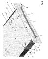
- a pleated filter 1 which consists of a pleated nonwoven and in Area of its long sides 13, 14 in each case a glued or welded Edge 23, 24 has, together with a cover 2, which in this embodiment consists of a polymeric material that is pre-assembled Unit 4.
- the pre-assembled unit 4 is during its intended use Inserted into the filter housing 3 in such a way that the pleated filter 1 is completely enclosed by the filter housing 3 and the Cover 2 touches the filter housing 3 at the end and seals.
- the Pleated filter 1 and the lid 2 touch each other directly in the sealing Area of the upstream last fold 6 of the pleated filter 1 and of the sword 5 of the lid 2. Since the pleated filter is a wearing part acts, which, if necessary, can be replaced separately and easily the pleated filter 1 is detachably connected to the cover 2 in a non-destructive manner.
- the pleated filter 1 is form-fitting connected to the cover, the positive connection by the upstream 8th sword 5 engaging in the last end fold 6 and the locking cams 19, 20 is formed.
- the locking cams 19, 20 hold the pleated filter 1 on the longitudinal rails 15, 16 of the abutment 12 down.
- the sword 5 causes a captive Assignment of the pleated filter 1 on the cover 2 in the longitudinal direction 25 of the Pleated filter 1, while the abutment 12 spatially viewed the pleated filter 1, fixed in the other two directions, based on the lid 2.
- the locking cams 19, 20 To remove the pleated filter 1 from the cover 2, the locking cams 19, 20 the holding clips 17, 18 transversely to the longitudinal direction 25 elastically outwards deformed until it meets the upstream boundaries 21, 22 of the long sides Release 13, 14 of the pleated filter 1. Then the pleated filter 1 past the locking cams 19, 20, starting from that facing away from the cover 2 End to be panned towards the viewer until the Sword 5 and the front last fold 6 of the pleated filter 1 out of engagement get and the pleated filter 1 and the lid 2 thereby non-destructive are detachable from each other.
- the assembly of the pleated filter 1 with the lid 2 to the preassembled unit 4 takes place in such a way that the pleated filter 1 with its last front pleat 6 is threaded under the sword 5 of the cover 2 on the upstream side 8. Meanwhile, the pleated filter 1 and the lid 2 close, depending on their Design, about an angle of 30 to 75 ° with each other. Subsequently the pleated filter 1 continues in the direction of the abutment 12 pivoted until the outflow-side boundaries 26, 27 of the long sides 13, 14 touch the longitudinal rails 15, 16 adjacent.
- the handle 10 is on the side 9 of the cover 2 facing away from the pleated filter 1 arranged, which is an integral and material-integral part of the Cover 2 forms. This handle 10 facilitates the assembly or disassembly of the pre-assembled unit 4 with the filter housing 3.
- FIG. 2 shows a section of the preassembled unit 4 from FIG. 1 in an enlarged view.
- the locking cams 19, 20 each have a run-up slope 28, 29 on the side facing the cover 2, which causes the pleated filter 1 to automatically expand the retaining clips 17, 18 transversely to the longitudinal direction 25 when it is mounted with the cover 2 to the preassembled unit 4 , The assembly of the pleated filter 1 with the cover 2 is thereby considerably simplified.
- the cover 2 is shown as an individual part in a perspective view obliquely from above.
- the two retaining clips 17, 18 are connected on the side facing away from the locking cams 19, 20 by a connecting web 30, which additionally ensures dimensional stability of the retaining clips 17, 18 formed integrally into one another and made of the same material as the cover 2, and thereby ensures sufficient pretension the retaining clips 17, 18 on the long sides 13, 14 of the pleated filter 1.
- the lid 2 is shown obliquely from below.
- the essentially L-shaped sword 5 arranged that on the upstream side 8 of the pleated filter 1 in the last end Fold 6 of the pleated filter 1 engages sealingly.
- the upstream side lays down last edge of the last end fold 6 sealing against the sword 5 and prevents leakage.
- the sword 5 forms a protection against loss and prevents the pleated filter 1 in the longitudinal direction 25 from the Holding clips 17, 18 of the cover 2 slips.
Landscapes
- Chemical & Material Sciences (AREA)
- Chemical Kinetics & Catalysis (AREA)
- Engineering & Computer Science (AREA)
- Mechanical Engineering (AREA)
- Combustion & Propulsion (AREA)
- General Engineering & Computer Science (AREA)
- Filtering Of Dispersed Particles In Gases (AREA)
- Separation By Low-Temperature Treatments (AREA)
- Piezo-Electric Or Mechanical Vibrators, Or Delay Or Filter Circuits (AREA)
- Oscillators With Electromechanical Resonators (AREA)
- Pharmaceuticals Containing Other Organic And Inorganic Compounds (AREA)
- Centrifugal Separators (AREA)
- Separation Using Semi-Permeable Membranes (AREA)
Abstract
Description
Dabei ist allerdings zu beachten, dass die Montage einer solchen Filteranordnung wenig zufriedenstellend ist. Die räumliche Zuordnung und/oder die Abdichtung von Faltenfilter und Deckel zueinander ist im Wesentlichen von den Fähigkeiten und der Zuverlässigkeit des Monteurs abhängig, wobei fehlerhaft montierte Faltenfilter und/oder Deckel häufig zu unerwünschten Undichtigkeiten und/oder zu einem Strömungs-Kurzschluss zwischen der An- und Abströmseite des Faltenfilters führen. Der Montageaufwand am Band und bei schlechter Zugänglichkeit des Filtergehäuses ist beträchtlich.
Im Hinblick auf den, bezogen auf den Deckel, vergleichsweise empfindlichen Faltenfilter, der aus einem Vliesstoff bestehen kann, wird einer hauptsächlich formschlüssigen Verbindung von Faltenfilter und Deckel im Rahmen der vorliegenden Erfindung der Vorzug gegeben. Die mechanischen Belastungen auf den Faltenfilter während der Montage sind dadurch weitesgehend reduziert.
- Fig. 1
- ein Ausführungsbeispiel der erfindungsgemäßen Filteranordnung, wobei die vormontierbare Einheit teilweise in ein Filtergehäuse eingeschoben ist,
- Fig. 2
- einen vergrößerten Ausschnitt der vormontierbaren Einheit aus Fig. 1,
- Fig. 3
- den Deckel als Einzelteil in perspektivischer Darstellung von schräg oben,
- Fig. 4
- den Deckel aus Fig. 3 in einer perspektivischen Ansicht von schräg unten.
In Fig. 3 ist der Deckel 2 als Einzelteil in einer perspektivischen Darstellung von schräg oben gezeigt. Die beiden Halteklammern 17, 18 sind auf der den Rastnocken 19, 20 abgewandten Seite durch einen Verbindungssteg 30 verbunden, der zusätzlich für eine Formbeständigkeit der einstückig ineinander übergehend und materialeinheitlich mit dem Deckel 2 ausgebildeten Halteklammern 17, 18 sorgt, und dadurch für eine ausreichende Vorspannung der Halteklammern 17, 18 an den Längsseiten 13, 14 des Faltenfilters 1.
- 1
- Faltenfilter
- 2
- Deckel
- 3
- Filtergehäuse
- 4
- Vormontierbare Einheit, bestehend aus 1 und 2
- 5
- Schwert
- 6
- Letzte Falte (anströmseitig)
- 7
- Stirnseite von 1
- 8
- Anströmseite von 1
- 9
- Seite des Griffs an 2
- 10
- Griff
- 11
- Seite des Faltenfilters an 2
- 12
- Widerlager
- 13
- Längsseite von 1, links
- 14
- Längsseite von 1, rechts
- 15
- Längsschiene, links
- 16
- Längsschiene, rechts
- 17
- Halteklammer, links
- 18
- Halteklammer, rechts
- 19
- Rastnocken, links
- 20
- Rastnocken, rechts
- 21
- Anströmsseitige Begrenzung von 13
- 22
- Anströmsseitige Begrenzung von 14
- 23
- Kante an 1, links
- 24
- Kante an 1, rechts
- 25
- Längsrichtung von 1
- 26
- Abströmseitige Begrenzung von 13
- 27
- Abströmseitige Begrenzung von 14
- 28
- Auflaufschräge von 19
- 29
- Auflaufschräge von 20
- 30
- Verbindungssteg
- 31
- Abströmseite von 1
Claims (17)
- Filteranordnung, umfassend einen Faltenfilter (1) und einen Deckel (2) eines Filtergehäuses (3), wobei der Faltenfilter (1) und der Deckel (2) eine vormontierbare Einheit (4) bilden und zerstörungsfrei lösbar sowie im Wesentlichen dichtend miteinander verbunden sind.
- Filteranordnung nach Anspruch 1, dadurch gekennzeichnet, dass der Faltenfilter (1) und der Deckel (2) kraft- und/oder formschlüssig miteinander verbunden sind.
- Filteranordnung nach einem der Ansprüche 1 oder 2, dadurch gekennzeichnet, dass der Deckel (2) aus einem polymeren Werkstoff besteht.
- Filteranordnung nach einem der Ansprüche 1 bis 3, dadurch gekennzeichnet, dass der Deckel (2) ein Schwert (5) aufweist, das in der dem Deckel (2) zugewandten, letzten Falte (6) der Stirnseite (7) des Faltenfilters (1) im Wesentlichen dichtend angeordnet ist.
- Filteranordnung nach Anspruch 4, dadurch gekennzeichnet, dass das Schwert (5) auf der Anströmseite (8) des Faltenfilters (1) in der letzten stirnseitigen Falte (6) angeordnet ist.
- Filteranordnung nach einem der Ansprüche 1 bis 5, dadurch gekennzeichnet, dass der Deckel (2) und das Schwert (5) einstückig und materialeinheitlich ausgebildet sind.
- Filteranordnung nach einem der Ansprüche 4 bis 6, dadurch gekennzeichnet, dass das Schwert (5) im Wesentlichen L-förmig ausgebildet ist.
- Filteranordnung nach einem der Ansprüche 1 bis 7, dadurch gekennzeichnet, dass der Deckel (2) auf der dem Faltenfilter (1) abgewandten Seite (9) einen Griff (10) zur Montage oder Demontage der vormontierbaren Einheit (4) aufweist.
- Filteranordnung nach einem der Ansprüche 1 bis 8, dadurch gekennzeichnet, dass der Deckel (2) und der Griff (10) einstückig und materialeinheitlich ausgebildet sind.
- Filteranordnung nach einem der Ansprüche 1 bis 9, dadurch gekennzeichnet, dass der Deckel (2) auf der dem Faltenfilter (1) zugewandten Seite (11) ein Widerlager (12) zur Lagerung des Faltenfilters (1) am Deckel (2) aufweist.
- Filteranordnung nach einem der Ansprüche 1 bis 10, dadurch gekennzeichnet, dass der Deckel (2) und das Widerlager (12) einstückig und materialeinheitlich ausgebildet sind.
- Filteranordnung nach einem der Ansprüche 10 oder 11, dadurch gekennzeichnet, dass das Widerlager (12) durch zwei die Längsseiten (13, 14) des Faltenfilters (1) abströmseitig zumindest teilweise untergreifende Längsschienen (15, 16) gebildet ist.
- Filteranordnung nach einem der Ansprüche 10 bis 12, dadurch gekennzeichnet, dass das Widerlager (12) durch zwei die Längsseiten (13, 14) des Faltenfilters (1) zumindest teilweise U-förmig umgreifende Halteklammern (17, 18) gebildet ist.
- Filteranordnung nach einem der Ansprüche 12 oder 13, dadurch gekennzeichnet, dass die Längsschienen (15, 16) einen Bestandteil der Halteklammern (17, 18) bilden.
- Filteranordnung nach einem der Ansprüche 10 bis 14, dadurch gekennzeichnet, dass das Widerlager (12) auf zumindest einer Längsseite (13, 14) des Faltenfilters (1) zumindest einen elastisch nachgiebigen Rastnocken (19, 20) aufweist, der die anströmseitige Begrenzung (21, 22) der entsprechenden Längsseite (13, 14) zumindest teilweise überdeckt.
- Filteranordnung nach einem der Ansprüche 1 bis 15, dadurch gekennzeichnet, dass jede Längsseite (13, 14) des Faltenfilters (1) anströmseitig von jeweils zumindest einem elastisch nachgiebigen Rastnocken (19, 20) zumindest teilweise überdeckt ist.
- Filteranordnung nach einem der Ansprüche 1 bis 16, dadurch gekennzeichnet, dass der Faltenfilter (1) mittels der Rastnocken (19, 20) in das Widerlager (12) einschnappbar ist.
Applications Claiming Priority (2)
| Application Number | Priority Date | Filing Date | Title |
|---|---|---|---|
| DE10123969A DE10123969C1 (de) | 2001-05-17 | 2001-05-17 | Filteranordnung |
| DE10123969 | 2001-05-17 |
Publications (2)
| Publication Number | Publication Date |
|---|---|
| EP1260263A1 true EP1260263A1 (de) | 2002-11-27 |
| EP1260263B1 EP1260263B1 (de) | 2004-10-06 |
Family
ID=7685095
Family Applications (1)
| Application Number | Title | Priority Date | Filing Date |
|---|---|---|---|
| EP02004588A Expired - Lifetime EP1260263B1 (de) | 2001-05-17 | 2002-02-28 | Filteranordnung |
Country Status (11)
| Country | Link |
|---|---|
| US (1) | US6749657B2 (de) |
| EP (1) | EP1260263B1 (de) |
| JP (1) | JP3766812B2 (de) |
| KR (1) | KR100485009B1 (de) |
| AT (1) | ATE278451T1 (de) |
| BR (1) | BR0201856B1 (de) |
| CZ (1) | CZ299328B6 (de) |
| DE (2) | DE10123969C1 (de) |
| ES (1) | ES2228996T3 (de) |
| PL (1) | PL200144B1 (de) |
| ZA (1) | ZA200203923B (de) |
Cited By (3)
| Publication number | Priority date | Publication date | Assignee | Title |
|---|---|---|---|---|
| FR2865159A1 (fr) * | 2004-01-21 | 2005-07-22 | Valeo Climatisation | Dispositif d'obturation d'une installation de ventilation, chauffage et/ou climatisation facilitant l'acces a un moyen de filtration. |
| EP2397210A1 (de) * | 2010-06-17 | 2011-12-21 | Carl Freudenberg KG | Anordnung mit einem Deckel und einem selbsttragenden Filterelement |
| FR3022470A1 (fr) * | 2014-06-18 | 2015-12-25 | Sandra Celine Severine Lefrancois | Boitier porte-cartouche filtrantes contre les pollutions exterieures, dispose sur entrees d'aire murals, des portes, fenetres, coffres de volet roulant couples aux ventilations mecaniques. |
Families Citing this family (15)
| Publication number | Priority date | Publication date | Assignee | Title |
|---|---|---|---|---|
| DE10317493B4 (de) * | 2003-01-24 | 2007-06-14 | Helsa-Automotive Gmbh & Co. Kg | Filterelement für eine Filteraufnahme |
| TWI354011B (en) * | 2003-05-16 | 2011-12-11 | Semiconductor Energy Lab | Carbazole derivative, organic semiconductor elemen |
| DE10334567A1 (de) * | 2003-07-28 | 2005-02-24 | Behr Gmbh & Co. Kg | Filteranordnung |
| DE10356311A1 (de) * | 2003-11-28 | 2005-06-23 | Behr Gmbh & Co. Kg | Filteranordnung |
| DE102005019675A1 (de) * | 2005-04-26 | 2006-11-02 | Behr Gmbh & Co. Kg | Filtereinheit und Belüftungsanlage |
| US7597735B2 (en) * | 2006-12-21 | 2009-10-06 | Cummins Filtration Ip Inc. | Apparatus and system for uniform sealing force in an air filter assembly |
| DE202008010474U1 (de) | 2008-08-06 | 2009-12-17 | Mann+Hummel Gmbh | Filtersystem |
| KR101016549B1 (ko) * | 2010-08-12 | 2011-02-24 | 비에이치아이 주식회사 | 복수의 만곡부를 포함하는 스트레이너 벽 구조체 및 그 스트레이너 벽 구조체의 제조방법 및 그 스트레이너 벽 구조체를 이용한 여과방법 |
| JP6262513B2 (ja) * | 2013-12-12 | 2018-01-17 | 株式会社日本クライメイトシステムズ | 車両用空調装置 |
| DE102015203138A1 (de) | 2015-02-20 | 2016-08-25 | Mahle International Gmbh | Luftfilterelement und Luftfilter |
| IT201800009906A1 (it) | 2018-10-30 | 2020-04-30 | Denso Thermal Systems Spa | Coperchio per elemento filtrante. |
| CN212700928U (zh) * | 2020-04-29 | 2021-03-16 | 赛格威科技有限公司 | 过滤装置及全地形车 |
| JP7305048B2 (ja) * | 2020-06-23 | 2023-07-07 | 三菱電機株式会社 | フィルター枠および換気装置 |
| CN112304341A (zh) * | 2020-10-22 | 2021-02-02 | 上海工程技术大学 | 一种可抗强电磁场干扰检测设备 |
| US12491460B2 (en) * | 2021-09-30 | 2025-12-09 | Carrier Corporation | Duct mounted filtering apparatus |
Citations (9)
| Publication number | Priority date | Publication date | Assignee | Title |
|---|---|---|---|---|
| US2655091A (en) * | 1950-08-07 | 1953-10-13 | Rex W Geiger | Filter |
| US4925468A (en) * | 1987-10-14 | 1990-05-15 | Nippondenso Co., Ltd. | Filter device provided in an air conditioning device |
| US5030264A (en) * | 1989-04-06 | 1991-07-09 | Filterwerk Mann & Hummel Gmbh | Air intake filter for an internal combustion engine |
| US5435837A (en) * | 1993-12-06 | 1995-07-25 | Lewis; Keith B. | Ion generation structure in environmental systems |
| EP0684152A1 (de) * | 1994-05-25 | 1995-11-29 | Honda Giken Kogyo Kabushiki Kaisha | Luftfilter-Montageanordnung in einer Klimaanlage |
| US5494497A (en) * | 1992-12-30 | 1996-02-27 | Hyundai Motor Company | Air cleaner assembly for vehicle |
| EP0744309A1 (de) * | 1995-05-26 | 1996-11-27 | FIAT AUTO S.p.A. | Luftfilter für eine Klimaanlage, insbesondere für Kraftfahrzeuge |
| US6089202A (en) * | 1997-08-21 | 2000-07-18 | Denso Corporation | Air-supply module for internal combustion engine |
| GB2348153A (en) * | 1999-03-25 | 2000-09-27 | Draftex Ind Ltd | Easily removable air filter for internal combustion engine air intake. |
Family Cites Families (15)
| Publication number | Priority date | Publication date | Assignee | Title |
|---|---|---|---|---|
| US4773922A (en) * | 1987-07-22 | 1988-09-27 | The United States Of America As Represented By The United States Department Of Energy | Remotely serviced filter and housing |
| US4900344A (en) * | 1987-11-10 | 1990-02-13 | Jvj Enterprises, Inc. | Portable room air filter |
| DE4329367C1 (de) * | 1993-09-01 | 1995-04-27 | Juergen Junker | Filtereinsatz |
| US5639287A (en) * | 1994-05-16 | 1997-06-17 | Minnesota Mining And Manufacturing Company | Filter system for filtering fluids |
| DE4443676C2 (de) * | 1994-12-08 | 1998-08-13 | Hengst Walter Gmbh & Co Kg | Filter mit einem Filtergehäuse und einem darin angeordneten auswechselbaren Filterelement |
| JP3379275B2 (ja) * | 1995-04-21 | 2003-02-24 | 日産自動車株式会社 | 車両用空調装置およびそのフィルタ取付構造 |
| JPH09290630A (ja) * | 1996-04-30 | 1997-11-11 | Nissan Motor Co Ltd | 車両用空調フィルター |
| AU4901297A (en) * | 1996-10-18 | 1998-05-15 | Rick L. Chapman | High efficiency permanent air filter |
| US5740774A (en) * | 1996-12-18 | 1998-04-21 | Siemens Electric Limited | Engine induction air system having improved air filter accessibility |
| KR19980046748U (ko) * | 1996-12-28 | 1998-09-25 | 박병재 | 자동차의 블로어 필터 |
| US6033453A (en) * | 1997-01-30 | 2000-03-07 | Weddell, Iii; Robert W. | Re-usable frame support rack for replaceable pleated-media filter core |
| US5865863A (en) * | 1997-05-08 | 1999-02-02 | Siemens Electric Limited | Combined air cleaner-resonator |
| DE19850576C2 (de) * | 1998-11-03 | 2002-06-27 | Freudenberg Carl Kg | Filterpatronenanordnung |
| FR2806318B1 (fr) * | 2000-03-15 | 2002-10-25 | Valeo | Dispositif de filtration destine a equiper un appareil d'aeration et/ou de chauffage et/ou de climatisation, notamment pour vehicule automobile |
| US6419718B1 (en) * | 2000-10-13 | 2002-07-16 | Donaldson Company, Inc. | Cover member and air cleaner construction; use; and, method of assembly |
-
2001
- 2001-05-17 DE DE10123969A patent/DE10123969C1/de not_active Expired - Fee Related
-
2002
- 2002-02-28 ES ES02004588T patent/ES2228996T3/es not_active Expired - Lifetime
- 2002-02-28 DE DE50201191T patent/DE50201191D1/de not_active Expired - Lifetime
- 2002-02-28 EP EP02004588A patent/EP1260263B1/de not_active Expired - Lifetime
- 2002-02-28 AT AT02004588T patent/ATE278451T1/de not_active IP Right Cessation
- 2002-03-13 CZ CZ20020902A patent/CZ299328B6/cs not_active IP Right Cessation
- 2002-04-25 PL PL353632A patent/PL200144B1/pl not_active IP Right Cessation
- 2002-05-15 KR KR10-2002-0026769A patent/KR100485009B1/ko not_active Expired - Fee Related
- 2002-05-16 US US10/150,246 patent/US6749657B2/en not_active Expired - Fee Related
- 2002-05-16 ZA ZA200203923A patent/ZA200203923B/xx unknown
- 2002-05-17 BR BRPI0201856-0A patent/BR0201856B1/pt not_active IP Right Cessation
- 2002-05-17 JP JP2002143519A patent/JP3766812B2/ja not_active Expired - Fee Related
Patent Citations (9)
| Publication number | Priority date | Publication date | Assignee | Title |
|---|---|---|---|---|
| US2655091A (en) * | 1950-08-07 | 1953-10-13 | Rex W Geiger | Filter |
| US4925468A (en) * | 1987-10-14 | 1990-05-15 | Nippondenso Co., Ltd. | Filter device provided in an air conditioning device |
| US5030264A (en) * | 1989-04-06 | 1991-07-09 | Filterwerk Mann & Hummel Gmbh | Air intake filter for an internal combustion engine |
| US5494497A (en) * | 1992-12-30 | 1996-02-27 | Hyundai Motor Company | Air cleaner assembly for vehicle |
| US5435837A (en) * | 1993-12-06 | 1995-07-25 | Lewis; Keith B. | Ion generation structure in environmental systems |
| EP0684152A1 (de) * | 1994-05-25 | 1995-11-29 | Honda Giken Kogyo Kabushiki Kaisha | Luftfilter-Montageanordnung in einer Klimaanlage |
| EP0744309A1 (de) * | 1995-05-26 | 1996-11-27 | FIAT AUTO S.p.A. | Luftfilter für eine Klimaanlage, insbesondere für Kraftfahrzeuge |
| US6089202A (en) * | 1997-08-21 | 2000-07-18 | Denso Corporation | Air-supply module for internal combustion engine |
| GB2348153A (en) * | 1999-03-25 | 2000-09-27 | Draftex Ind Ltd | Easily removable air filter for internal combustion engine air intake. |
Cited By (3)
| Publication number | Priority date | Publication date | Assignee | Title |
|---|---|---|---|---|
| FR2865159A1 (fr) * | 2004-01-21 | 2005-07-22 | Valeo Climatisation | Dispositif d'obturation d'une installation de ventilation, chauffage et/ou climatisation facilitant l'acces a un moyen de filtration. |
| EP2397210A1 (de) * | 2010-06-17 | 2011-12-21 | Carl Freudenberg KG | Anordnung mit einem Deckel und einem selbsttragenden Filterelement |
| FR3022470A1 (fr) * | 2014-06-18 | 2015-12-25 | Sandra Celine Severine Lefrancois | Boitier porte-cartouche filtrantes contre les pollutions exterieures, dispose sur entrees d'aire murals, des portes, fenetres, coffres de volet roulant couples aux ventilations mecaniques. |
Also Published As
| Publication number | Publication date |
|---|---|
| ZA200203923B (en) | 2004-05-17 |
| ES2228996T3 (es) | 2005-04-16 |
| BR0201856A (pt) | 2004-04-13 |
| BR0201856B1 (pt) | 2010-11-16 |
| ATE278451T1 (de) | 2004-10-15 |
| US20030005671A1 (en) | 2003-01-09 |
| DE10123969C1 (de) | 2002-11-07 |
| KR20020088369A (ko) | 2002-11-27 |
| PL353632A1 (en) | 2002-11-18 |
| DE50201191D1 (de) | 2004-11-11 |
| EP1260263B1 (de) | 2004-10-06 |
| JP2003053122A (ja) | 2003-02-25 |
| CZ2002902A3 (cs) | 2003-01-15 |
| PL200144B1 (pl) | 2008-12-31 |
| CZ299328B6 (cs) | 2008-06-18 |
| US6749657B2 (en) | 2004-06-15 |
| KR100485009B1 (ko) | 2005-04-25 |
| JP3766812B2 (ja) | 2006-04-19 |
Similar Documents
| Publication | Publication Date | Title |
|---|---|---|
| EP3079794B1 (de) | Innenraumfilter und filteranordnung | |
| EP1260263B1 (de) | Filteranordnung | |
| EP1005893B1 (de) | Filterelement | |
| WO2015193341A2 (de) | Filter und filtereinsatz | |
| DE9305767U1 (de) | Luftfilter für den Innenraum von Kraftfahrzeugen | |
| DE102011015062B4 (de) | Filtergehäuse eines Luftfilters und Verschlusselement eines Filtergehäuses | |
| EP3421112B1 (de) | Flachfilterelement, insbesondere zur gasfiltration | |
| DE4443144C1 (de) | Taschenfilter | |
| DE20122455U1 (de) | Flexibler Filter | |
| DE102015011339A1 (de) | Filterelement mit einer umlaufenden Dichtung | |
| EP2692559B1 (de) | Luftfiltereinrichtung mit Filterelement | |
| EP2463009A1 (de) | Filterelement und Gehäuse zur Aufnahme des Filterelements | |
| EP3446768B1 (de) | Innenraumluftfilter und filteranordnung | |
| DE102020110996A1 (de) | Filterelement für eine Luftfiltereinrichtung eines Kraftwagens und Luftfiltereinrichtung | |
| DE102012012669A1 (de) | Luftfilter für eine Belüftungseinrichtung eines Fahrzeugs und Luftfilteranordnung | |
| DE3524278A1 (de) | Leitungsdurchfuehrung fuer durch eine gehaeusewand hindurchzufuehrende leitungen, insbesondere schlauch- und/oder rohrleitungen | |
| EP1616736A1 (de) | Faltenfiltereinsatz | |
| EP2582442B1 (de) | Filteranordnung, insbesondere luftfilteranordnung | |
| DE102022125133A1 (de) | Filtervorrichtung, Fahrzeug, Verwendung und Verfahren | |
| DE10249110A1 (de) | Filtereinrichtung, Filterelement und Filterrahmen | |
| DE10320260C5 (de) | Filter für eine Filteraufnahme, insbesondere für eine in einem Kraftfahrzeug vorgesehene Filteraufnahme | |
| DE102007015662A1 (de) | Filteranordnung | |
| DE102008027847A1 (de) | Luftfilter, insbesondere für die Ansaugluft einer Brennkraftmaschine | |
| DE202005011078U1 (de) | Abdichtelement für eine Filteraufnahme | |
| DE102010047894A1 (de) | Filterelement und Verfahren zu dessen Herstellung |
Legal Events
| Date | Code | Title | Description |
|---|---|---|---|
| PUAI | Public reference made under article 153(3) epc to a published international application that has entered the european phase |
Free format text: ORIGINAL CODE: 0009012 |
|
| AK | Designated contracting states |
Kind code of ref document: A1 Designated state(s): AT BE CH CY DE DK ES FI FR GB GR IE IT LI LU MC NL PT SE TR |
|
| AX | Request for extension of the european patent |
Free format text: AL;LT;LV;MK;RO;SI |
|
| 17P | Request for examination filed |
Effective date: 20030509 |
|
| AKX | Designation fees paid |
Designated state(s): AT BE CH CY DE DK ES FI FR GB GR IE IT LI LU MC NL PT SE TR |
|
| 17Q | First examination report despatched |
Effective date: 20031027 |
|
| GRAP | Despatch of communication of intention to grant a patent |
Free format text: ORIGINAL CODE: EPIDOSNIGR1 |
|
| GRAS | Grant fee paid |
Free format text: ORIGINAL CODE: EPIDOSNIGR3 |
|
| GRAA | (expected) grant |
Free format text: ORIGINAL CODE: 0009210 |
|
| AK | Designated contracting states |
Kind code of ref document: B1 Designated state(s): AT BE CH CY DE DK ES FI FR GB GR IE IT LI LU MC NL PT SE TR |
|
| PG25 | Lapsed in a contracting state [announced via postgrant information from national office to epo] |
Ref country code: TR Free format text: LAPSE BECAUSE OF FAILURE TO SUBMIT A TRANSLATION OF THE DESCRIPTION OR TO PAY THE FEE WITHIN THE PRESCRIBED TIME-LIMIT Effective date: 20041006 Ref country code: IE Free format text: LAPSE BECAUSE OF FAILURE TO SUBMIT A TRANSLATION OF THE DESCRIPTION OR TO PAY THE FEE WITHIN THE PRESCRIBED TIME-LIMIT Effective date: 20041006 Ref country code: FI Free format text: LAPSE BECAUSE OF FAILURE TO SUBMIT A TRANSLATION OF THE DESCRIPTION OR TO PAY THE FEE WITHIN THE PRESCRIBED TIME-LIMIT Effective date: 20041006 |
|
| REG | Reference to a national code |
Ref country code: GB Ref legal event code: FG4D Free format text: NOT ENGLISH |
|
| REG | Reference to a national code |
Ref country code: CH Ref legal event code: EP |
|
| REG | Reference to a national code |
Ref country code: IE Ref legal event code: FG4D Free format text: GERMAN |
|
| REF | Corresponds to: |
Ref document number: 50201191 Country of ref document: DE Date of ref document: 20041111 Kind code of ref document: P |
|
| RAP2 | Party data changed (patent owner data changed or rights of a patent transferred) |
Owner name: BEHR GMBH & CO. KG Owner name: CARL FREUDENBERG KG |
|
| GBT | Gb: translation of ep patent filed (gb section 77(6)(a)/1977) |
Effective date: 20041125 |
|
| PG25 | Lapsed in a contracting state [announced via postgrant information from national office to epo] |
Ref country code: GR Free format text: LAPSE BECAUSE OF FAILURE TO SUBMIT A TRANSLATION OF THE DESCRIPTION OR TO PAY THE FEE WITHIN THE PRESCRIBED TIME-LIMIT Effective date: 20050106 Ref country code: DK Free format text: LAPSE BECAUSE OF FAILURE TO SUBMIT A TRANSLATION OF THE DESCRIPTION OR TO PAY THE FEE WITHIN THE PRESCRIBED TIME-LIMIT Effective date: 20050106 |
|
| REG | Reference to a national code |
Ref country code: SE Ref legal event code: TRGR |
|
| NLT2 | Nl: modifications (of names), taken from the european patent patent bulletin |
Owner name: CARL FREUDENBERG KG EN BEHR GMBH & CO. KG |
|
| PG25 | Lapsed in a contracting state [announced via postgrant information from national office to epo] |
Ref country code: CY Free format text: LAPSE BECAUSE OF FAILURE TO SUBMIT A TRANSLATION OF THE DESCRIPTION OR TO PAY THE FEE WITHIN THE PRESCRIBED TIME-LIMIT Effective date: 20050228 Ref country code: AT Free format text: LAPSE BECAUSE OF NON-PAYMENT OF DUE FEES Effective date: 20050228 Ref country code: LU Free format text: LAPSE BECAUSE OF NON-PAYMENT OF DUE FEES Effective date: 20050228 Ref country code: MC Free format text: LAPSE BECAUSE OF NON-PAYMENT OF DUE FEES Effective date: 20050228 |
|
| REG | Reference to a national code |
Ref country code: ES Ref legal event code: FG2A Ref document number: 2228996 Country of ref document: ES Kind code of ref document: T3 |
|
| REG | Reference to a national code |
Ref country code: IE Ref legal event code: FD4D |
|
| ET | Fr: translation filed | ||
| NLT1 | Nl: modifications of names registered in virtue of documents presented to the patent office pursuant to art. 16 a, paragraph 1 |
Owner name: CARL FREUDENBERG KG Owner name: BEHR GMBH & CO. KG |
|
| PLBE | No opposition filed within time limit |
Free format text: ORIGINAL CODE: 0009261 |
|
| STAA | Information on the status of an ep patent application or granted ep patent |
Free format text: STATUS: NO OPPOSITION FILED WITHIN TIME LIMIT |
|
| 26N | No opposition filed |
Effective date: 20050707 |
|
| PG25 | Lapsed in a contracting state [announced via postgrant information from national office to epo] |
Ref country code: CH Free format text: LAPSE BECAUSE OF NON-PAYMENT OF DUE FEES Effective date: 20060228 Ref country code: LI Free format text: LAPSE BECAUSE OF NON-PAYMENT OF DUE FEES Effective date: 20060228 |
|
| REG | Reference to a national code |
Ref country code: CH Ref legal event code: PL |
|
| PG25 | Lapsed in a contracting state [announced via postgrant information from national office to epo] |
Ref country code: PT Free format text: LAPSE BECAUSE OF NON-PAYMENT OF DUE FEES Effective date: 20050306 |
|
| PGFP | Annual fee paid to national office [announced via postgrant information from national office to epo] |
Ref country code: NL Payment date: 20090226 Year of fee payment: 8 |
|
| PGFP | Annual fee paid to national office [announced via postgrant information from national office to epo] |
Ref country code: GB Payment date: 20090223 Year of fee payment: 8 |
|
| PGFP | Annual fee paid to national office [announced via postgrant information from national office to epo] |
Ref country code: BE Payment date: 20090302 Year of fee payment: 8 |
|
| PGFP | Annual fee paid to national office [announced via postgrant information from national office to epo] |
Ref country code: IT Payment date: 20090219 Year of fee payment: 8 Ref country code: SE Payment date: 20090223 Year of fee payment: 8 |
|
| BERE | Be: lapsed |
Owner name: CARL *FREUDENBERG K.G. Effective date: 20100228 Owner name: *BEHR G.M.B.H. & CO. Effective date: 20100228 |
|
| REG | Reference to a national code |
Ref country code: NL Ref legal event code: V1 Effective date: 20100901 |
|
| GBPC | Gb: european patent ceased through non-payment of renewal fee |
Effective date: 20100228 |
|
| EUG | Se: european patent has lapsed | ||
| PG25 | Lapsed in a contracting state [announced via postgrant information from national office to epo] |
Ref country code: NL Free format text: LAPSE BECAUSE OF NON-PAYMENT OF DUE FEES Effective date: 20100901 |
|
| PG25 | Lapsed in a contracting state [announced via postgrant information from national office to epo] |
Ref country code: BE Free format text: LAPSE BECAUSE OF NON-PAYMENT OF DUE FEES Effective date: 20100228 |
|
| PG25 | Lapsed in a contracting state [announced via postgrant information from national office to epo] |
Ref country code: IT Free format text: LAPSE BECAUSE OF NON-PAYMENT OF DUE FEES Effective date: 20100228 Ref country code: GB Free format text: LAPSE BECAUSE OF NON-PAYMENT OF DUE FEES Effective date: 20100228 |
|
| PGFP | Annual fee paid to national office [announced via postgrant information from national office to epo] |
Ref country code: FR Payment date: 20110307 Year of fee payment: 10 Ref country code: DE Payment date: 20110315 Year of fee payment: 10 |
|
| PGFP | Annual fee paid to national office [announced via postgrant information from national office to epo] |
Ref country code: ES Payment date: 20110225 Year of fee payment: 10 |
|
| PG25 | Lapsed in a contracting state [announced via postgrant information from national office to epo] |
Ref country code: SE Free format text: LAPSE BECAUSE OF NON-PAYMENT OF DUE FEES Effective date: 20100301 |
|
| REG | Reference to a national code |
Ref country code: FR Ref legal event code: ST Effective date: 20121031 |
|
| REG | Reference to a national code |
Ref country code: DE Ref legal event code: R119 Ref document number: 50201191 Country of ref document: DE Effective date: 20120901 |
|
| PG25 | Lapsed in a contracting state [announced via postgrant information from national office to epo] |
Ref country code: FR Free format text: LAPSE BECAUSE OF NON-PAYMENT OF DUE FEES Effective date: 20120229 |
|
| PG25 | Lapsed in a contracting state [announced via postgrant information from national office to epo] |
Ref country code: DE Free format text: LAPSE BECAUSE OF NON-PAYMENT OF DUE FEES Effective date: 20120901 |
|
| REG | Reference to a national code |
Ref country code: ES Ref legal event code: FD2A Effective date: 20130708 |
|
| PG25 | Lapsed in a contracting state [announced via postgrant information from national office to epo] |
Ref country code: ES Free format text: LAPSE BECAUSE OF NON-PAYMENT OF DUE FEES Effective date: 20120301 |