EP1260424A2 - Unité de transmission - Google Patents
Unité de transmission Download PDFInfo
- Publication number
- EP1260424A2 EP1260424A2 EP02003245A EP02003245A EP1260424A2 EP 1260424 A2 EP1260424 A2 EP 1260424A2 EP 02003245 A EP02003245 A EP 02003245A EP 02003245 A EP02003245 A EP 02003245A EP 1260424 A2 EP1260424 A2 EP 1260424A2
- Authority
- EP
- European Patent Office
- Prior art keywords
- rotor
- transmission unit
- stator
- driver
- steering angle
- Prior art date
- Legal status (The legal status is an assumption and is not a legal conclusion. Google has not performed a legal analysis and makes no representation as to the accuracy of the status listed.)
- Granted
Links
Images





Classifications
-
- B—PERFORMING OPERATIONS; TRANSPORTING
- B60—VEHICLES IN GENERAL
- B60R—VEHICLES, VEHICLE FITTINGS, OR VEHICLE PARTS, NOT OTHERWISE PROVIDED FOR
- B60R16/00—Electric or fluid circuits specially adapted for vehicles and not otherwise provided for; Arrangement of elements of electric or fluid circuits specially adapted for vehicles and not otherwise provided for
- B60R16/02—Electric or fluid circuits specially adapted for vehicles and not otherwise provided for; Arrangement of elements of electric or fluid circuits specially adapted for vehicles and not otherwise provided for electric constitutive elements
- B60R16/023—Electric or fluid circuits specially adapted for vehicles and not otherwise provided for; Arrangement of elements of electric or fluid circuits specially adapted for vehicles and not otherwise provided for electric constitutive elements for transmission of signals between vehicle parts or subsystems
- B60R16/027—Electric or fluid circuits specially adapted for vehicles and not otherwise provided for; Arrangement of elements of electric or fluid circuits specially adapted for vehicles and not otherwise provided for electric constitutive elements for transmission of signals between vehicle parts or subsystems between relatively movable parts of the vehicle, e.g. between steering wheel and column
-
- B—PERFORMING OPERATIONS; TRANSPORTING
- B62—LAND VEHICLES FOR TRAVELLING OTHERWISE THAN ON RAILS
- B62D—MOTOR VEHICLES; TRAILERS
- B62D1/00—Steering controls, i.e. means for initiating a change of direction of the vehicle
- B62D1/02—Steering controls, i.e. means for initiating a change of direction of the vehicle vehicle-mounted
- B62D1/16—Steering columns
-
- B—PERFORMING OPERATIONS; TRANSPORTING
- B62—LAND VEHICLES FOR TRAVELLING OTHERWISE THAN ON RAILS
- B62D—MOTOR VEHICLES; TRAILERS
- B62D15/00—Steering not otherwise provided for
- B62D15/02—Steering position indicators ; Steering position determination; Steering aids
Definitions
- the invention relates to a transmission unit with a stationary stator that can be arranged on a vehicle and with one with the steering wheel or with the steering column Connectable rotor of the vehicle, with bearing means for rotatable bearing of the rotor in relation to the stator and with a winding tape for the transmission of electrical signals between the rotor and the stator.
- Transmission units are also available as coil spring connectors, Clock spring connector or airbag transmission units are known.
- the several Steering wheel rotations includes, stroke signals or ignition signals for Airbags are transmitted safely.
- the well-known Transmission units also see vehicles Steering angle sensors in front, one with the steering wheel or the Include steering column rotatably connected coding disc. Such sensors have the task of generating a signal generate which is characteristic of the steering angle or Steering angle change of the vehicle is.
- the present invention is therefore based on the object to provide a transmission unit that especially in combination with a steering angle sensor takes up as little space as possible. In addition, should use as few different components as possible.
- This task is carried out in a transmission unit initially mentioned type solved according to the invention in that a driver indirectly via a compensating piece with the Rotor is non-rotatably connected, with the Compensating piece a radial offset of the longitudinal axis of the Steering column and the axis of rotation of the driver balanced can be, and that to the driver a coding disc a steering angle measuring system can be attached.
- Such a transmission unit has the advantage that none for the coding disk of a steering angle measuring system separate storage must be provided. Rather, the Coding disc, if a steering angle sensor is provided, with the rotor over the compensating piece and the driver be attached in a rotationally fixed manner.
- the Coding disc if a steering angle sensor is provided, with the rotor over the compensating piece and the driver be attached in a rotationally fixed manner.
- Through the appropriate storage of the rotor relative to the stator ensures that a radial offset of the longitudinal axis of the steering column and the Axis of rotation of the driver, and thus the axis of rotation of one the driver-attachable coding disc, as well Runout of the steering column in relation to the stator be balanced.
- This has the advantage of being a radial offset of the longitudinal axis of the steering column and the Rotation axis of the encoder disc resulting angle errors that the Falsify measurement result of steering angle measuring system, be eliminated.
- Another advantage of the invention Transmission unit is that about the possibility of Arrangement of the coding disc of the steering angle measuring system no additional bearing for the rotor Coding disc is required.
- the transmission unit is therefore very compact.
- the bearing means on the sleeve-like section arranged on the rotor the one existing on the stator with a recess through and / or engages behind the predetermined radial play.
- the breakthrough formed by the sleeve-like portion here to accommodate the steering column. Because of the through and / or The stator recess can reach behind a given game both an axial and a radial storage realized in a simple manner become.
- the predetermined radial play is preferably 1 - 2 mm to avoid the effects of radial forces on the Prevent driver or on the coding disk. Concentricity errors of the steering column and / or the driver can be balanced without the red and / or the Stator is subject to an undesirably high load.
- the sleeve-like Section has locking means and in particular locking lugs, the corresponding with existing on the rotor Locking means, in particular locking bulges, interact.
- This has the advantage that in particular by axially inserting the rotor and the stator a locking takes place which the rotor in the axial direction secures against the stator.
- the sleeve-like section for storage and in particular for axial bearing of the rotor with a counterpart is screwable.
- the sleeve-like Section through the recess on the stator be inserted, the penetrating through the recess Section of the sleeve-like section with a Counterpart, especially with a lock nut, can be screwed.
- the locking means have a radial play between the rotor and the Ensure carriers. About this radial game can a radial offset of the longitudinal axis of the steering column and the Axis of rotation of the driver can be compensated. By the radial play can also compensate for radial runout become.
- the fact that the compensator between the Rotor and the carrier is held captive, the Rotor with driver and compensation piece as separate Assembly to be pre-assembled.
- the driver latches and / or Identifies latching bays with the coding disc according to existing resting bays and / or locking lugs interact.
- Such a locking connection has in particular the advantage that no additional Fasteners are to be provided.
- the Driver for fastening the coding disc with the Coding disc can be screwed.
- Driver in one piece with a coding disc Steering angle measuring system trained.
- This training is particularly advantageous if the invention Transmission unit with a steering angle measuring system is combined.
- the tour of the Coding disc increased because of the smaller number of Components with smaller tolerance deviations occur.
- the invention provides that on the stator, especially on the side facing away from the rotor Stator, a steering angle measuring system with means for detection the angular position of those which can be arranged on the driver Coding disk is arranged or can be arranged.
- a steering angle measuring system with means for detection the angular position of those which can be arranged on the driver Coding disk is arranged or can be arranged.
- the transmission unit is a steering angle measuring system according to the invention, it is conceivable that the rotor opposite side of the stator, and thus that Steering angle measuring system, with a housing closure part can be covered. This will make the steering angle measurement system ahead Protected from environmental influences.
- the transmission unit and in particular of the stator can be provided according to the invention be the side of the stator facing away from the rotor Has fasteners.
- the fasteners can in this case, in particular, latching hooks, the middle or can be locked directly to the vehicle.
- the transmission unit is a steering angle measuring system provides that is covered with a housing closure part
- Housing closure part has recesses through which the fasteners arranged on the stator grip.
- the stator can advantageously be identical Construction, regardless of whether the Transmission unit provides a steering angle measuring system or Not. Looks at the transmission unit Steering angle measuring system before, this is with the Housing closure part covered, the Fasteners through the on the housing closure part existing recesses protrude.
- housing closure part on the side facing away from the stator Fastening means for fastening the stator to the Vehicle.
- the stator to hold the Steering angle measuring system therefore differs from that Stator that has no steering angle measuring system and therefore no housing closure part with fasteners is provided, by the fastening means provided on the stator.
- Can be used to manufacture the stator without fasteners advantageously the same molds - except for those tool inserts that the Form fasteners - find use.
- Compensating piece is a compensating ring that is opposite the Rotor along a first radius and opposite to that Driver can be moved along a second radius, preferably the angle between the two radii Is 90 °.
- a compensating piece in particular a radial offset of the longitudinal axis of the Steering column and the axis of rotation of the driver or the Coding disk are compensated.
- This will advantageously ensures that the driver or the coding disk despite a relatively large, predetermined radial play of the rotor around a defined, predetermined Axis is rotatably supported with little play.
- the compensating piece has two directions Degrees of freedom that allow one, possibly existing offset of the longitudinal axis of the steering column and Axis of rotation of the driver and runout of the steering column and / or to compensate the driver.
- the compensating ring advantageously has one Side along the first radius and on the other side along the second radius two groove-like Recesses on, the facing the compensation ring Side of the rotor and the one facing the compensation ring Side of the driver two each in the corresponding Has recess-like web-like noses.
- This has the advantage of using very simple means Existing radial misalignment can be compensated for without that elaborate parts to manufacture, - the corresponding accordingly take up a lot of installation space, find use.
- the Compensation ring can be offset due to the offset arranged radii with the corresponding in radial Very flat in the direction of the groove-like recesses and thus be trained to save space. Corresponding flat and space-saving can the web-like, the Cut-out lugs on the rotor and on the Carriers are trained without this disadvantageous on the rotationally fixed connection of the coding disk with the steering wheel or with the steering column.
- Transmission unit 10 shown the one with a steering wheel or a steering column rotatably connectable rotor 12 includes.
- the transmission unit 10 is also called Clock spring connector or as an airbag transmission unit designated.
- the rotor 12 In the assembled state of the transmission unit 10, the rotor 12 is rotatable relative to a stator 14 stored.
- the Rotor 12 To connect to the steering wheel of a vehicle, the Rotor 12 on its top two pin elements 16 and a steering wheel connector socket 18.
- the steering wheel connector socket 18 is provided for receiving plug pins 20 which are on a connector carrier 22 are arranged.
- the connector pins 20 are on the steering wheel side arranged switches or triggers electrically connected.
- Fig. 1 also shows a winding tape 24 with a variety of parallel electrical Cables.
- the electrical lines of the winding tape 24 are at one end with the connector pins 20 and at the other end connected to a plug element 26.
- the plug element 26 When assembled the plug element 26 is stationary on the stator 14 arranged.
- the plug element 26 is for electrical Contact with the vehicle's electrical system is provided.
- the winding tape 24 is in the assembled state by one sleeve-like section 28 of the rotor 12 so loose wound that there is a multiple rotation of the rotor 12 about the rotor axis of rotation 30 in the two possible Permits directions of rotation.
- the sleeve-like section 28 surrounds a breakthrough 32 that does not hold a Steering column of a vehicle shown is provided.
- the sleeve-like section 28 also looks at its free Edge area several, extending in the axial direction, designed to be elastically resilient in the radial direction Locking hook 34 in front.
- the locking hooks 34 engage with one defined radial play of approx. 1 - 2 mm in a recess 36 of the stator 14, which is axially to the opening 32 of the Rotor 12 runs.
- the locking hooks 34 in the recess 36 thus rotatably support the rotor 12 in the stator 14.
- a driver 38 rotatably via a compensation piece in Form of a compensating ring 40 connected.
- the driver has one in the axial direction extending ring wall 42 on whose upper edge facing the rotor 12 is a radial outwardly extending collar 44 is arranged.
- the Carrier 38 also looks on the inside of the Ring wall 42 a radially inwardly extending Inner ring collar 46 in front.
- the ring wall 42 looks different Recesses 48 in front, for receiving the locking hook 34th serve.
- FIG Recess 50 shown in the ring wall 42 by which the inner ring collar 46 is visible.
- the latching hooks 34 engage axially in the recesses 48 of the ring wall 42 and engage with the edge region of the recess 36 of the stator 14.
- four locking hooks 34 are provided along the free edge of the sleeve-like section 28.
- the sleeve-like section 28 radially into the opening 32 projecting annular web 52.
- the Compensation ring 40 arranged between the web 52 of the rotor 12 and the Inner ring collar 46 of the carrier 38 held captive.
- the compensating ring 40 has two groove-like cutouts 54 on its side facing the rotor along a first radius r 1 .
- the compensating ring 40 On the side facing the driver 38, the compensating ring 40 has two further groove-like recesses 56 along a second radius r 2 .
- the angle between the two radii r 1 and r 2 is 90 °.
- Arranged on the web 52 of the rotor 12 are two web-like lugs 58 which run in the radial direction and which engage in the cutouts 54 in the assembled state.
- two further web-like lugs 60 are provided on the inner ring collar 46 of the driver 38, which webs engage in the groove-like recesses 56 of the compensating ring 40.
- the driver 38 thus has two degrees of freedom with respect to the rotor in the radial direction along the radii r 1 and r 2 , which make it possible to compensate for any misalignment of the longitudinal axis of the steering column and the axis of rotation of the driver as well as concentricity errors of the steering column and / or the driver.
- Such a bearing enables the compensation of a radial play of 1-2 mm of the rotor 12 in relation to the driver 38 which is mounted with little play.
- Fig. 1 also provides a fleece 62 which between the Wrapping tape 24 and the stator 14 for noise insulation Winding and unwinding the winding tape 24 is used.
- the section of the ring wall penetrating the stator 14 42 of driver 38 sees means in the form of indentations 64 before that for fastening one in Figs. 1, 2 and 3rd Serve coding disk, not shown.
- the fastening means 66 are used for connection of the stator 14 to the vehicle or to those in FIGS. 6 and 7 steering column switch 110 shown.
- the transmission unit 70 shown in FIG. 3 essentially corresponds to the transmission unit 10 according to FIG 1 and 2.
- the transmission unit 10 are for fastening the rotor 12 to the stator 14 no locking hooks 34 are provided. Rather, it is about the free A counterpart 72 in at the end of the sleeve-like section 28 Shape of a ring element attached. The attachment can in particular by screwing the counterpart 72 to the sleeve-like section 28 take place.
- stator 14 Between the sleeve-like section 28 or the counterpart 72 and the recess 36 of the rotor 12 receiving the A correspondingly large game is provided for stator 14, compared to the required mobility of the rotor 12 the stator 14 allows.
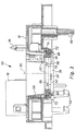
- the transmission unit 80 shown in FIGS. 4 and 5 comprises a steering angle measuring system 82.
- the under the Reference numerals 84 falling components correspond to Components of the transmission unit 10 according to FIGS. 1 and 2.
- the transmission unit 80 provides a stator 86 which has no fasteners and on its the rotor 12 side facing away from the steering angle measuring system 82 is suitable.
- FIG Coding disk of the steering angle measuring system 82 has one central breakthrough 90 on. Protrude into this opening 90 Locking lugs 92, which are used to fasten the coding disk 88 engage the indentations 64 on the driver 38. In order to the coding disk 88 can rotate on the driver 38 to be ordered.
- the coding disk 88 can be integrally formed with the driver 38.
- the steering angle measuring system 82 also sees a printed circuit board 94 before, on the different in the assembled state mechanical and electrical components 96 for scanning the Coding disk 88 or provided for steering angle detection are.
- the printed circuit board 94 is in the assembled state, as in FIG 5, on the side facing away from the rotor 12 of the stator 86 arranged.
- a housing closure part 98 present, that on its side facing away from the stator 84 Fastening and communication means 100, 120 corresponding to the fastening means 66 of the Transmission unit 10 and 70 has.
- Driver 38 becomes 80 in the transmission unit ensures that the encoder 88 regardless of any offset of the longitudinal axis of the Steering column and the axis of rotation of the coding disc uniform is rotated. Furthermore, runout errors of the steering column and / or the coding disk compensated.
- the transmission unit 80 corresponds, it can be provided that the fastening and Communication means not on the housing closure part 98, but on the side facing away from the rotor 12 Stator 84 are arranged.
- the fastening and Communication means take hold of such Embodiment, the printed circuit board 94 and the Housing closure part 98. This has the advantage that regardless of whether a transmission unit Steering angle measuring system provides or not, always on same housing closure part can be provided.
- the transmission unit 80 has the Advantage that the coding disk 88 indirectly over the Compensation ring 40 and the driver 38 in the bearing of the rotor 12 is stored. An additional depository for the coding disk 88 is therefore omitted. Also builds the transmission unit 80 with integrated Steering angle measuring system 82 very compact. Independent of a steering angle measuring system is provided, as in the Transmission unit 80 is the case, or not provided becomes, as is the case with the transmission unit 10 and 70 identical components are used.
- Transmission units 10, 70 and 80 are along a line by inserting the individual components are mountable.
- stator 14 or the housing closure part 98 has the Fastening and communication means 66 and 100, 120 on.
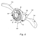
- FIG 6 shows the transmission unit 80 installed with a Steering column switch 110.
- Steering column switch 110 has a Basic housing 112, within which two shift levers 114 are arranged pivotably. Not to include one
- the steering column shown has the basic housing 112 in axial extension to the sleeve-like section 28 of the Rotor 12 has a central opening 116.
- the stator 14 is about the mounting and shown in Figure 5 Communication means 100 on the base housing 112 and above the base housing 112 is indirectly attached to the vehicle.
- the driver points 38 on its side facing away from the rotor 12 Driving web 102 extending in the axial direction.
- the carrier web 102 engages in the central opening 116 of the basic housing 112 of the Steering column switch 110 on.
- a switching lever 114 actuable switching function for example, a turn signal circuit can be canceled.
- the entrainment bar 102 acts with a corresponding, arranged in the base housing 112 Switching mechanism together.
- Plug element 26 of the transmission unit 80 is next to the Plug element 26 of the transmission unit 80 another Plug element 120 is provided, which for receiving the in the Figure 4 shown connector pins 122 of the Steering angle measuring system 82 is used.
- the connector element 120 is here along a line with the plug element 26 arranged.
- the steering column switch 110 is also electrical Has contacts and this also on the Transmission unit 80 facing away from the Steering column switch 110 are arranged Clock spring 24, the steering angle sensor 82 and the Switching electronics of the steering column switch 110 of the same Accessible from here. Can advantageously be provided be that via only one, to the base housing 112 dockable connector the clock spring 24, the Steering angle measuring system 82 and the switching electronics of the Steering column switch 110 with the vehicle electrical system be contacted.
Landscapes
- Engineering & Computer Science (AREA)
- Mechanical Engineering (AREA)
- Chemical & Material Sciences (AREA)
- Combustion & Propulsion (AREA)
- Transportation (AREA)
- Steering Controls (AREA)
- Measurement Of Length, Angles, Or The Like Using Electric Or Magnetic Means (AREA)
Applications Claiming Priority (2)
| Application Number | Priority Date | Filing Date | Title |
|---|---|---|---|
| DE10125403 | 2001-05-25 | ||
| DE10125403A DE10125403A1 (de) | 2001-05-25 | 2001-05-25 | Übertragungseinheit |
Publications (3)
| Publication Number | Publication Date |
|---|---|
| EP1260424A2 true EP1260424A2 (fr) | 2002-11-27 |
| EP1260424A3 EP1260424A3 (fr) | 2003-04-09 |
| EP1260424B1 EP1260424B1 (fr) | 2004-02-04 |
Family
ID=7686030
Family Applications (1)
| Application Number | Title | Priority Date | Filing Date |
|---|---|---|---|
| EP02003245A Expired - Lifetime EP1260424B1 (fr) | 2001-05-25 | 2002-02-21 | Unité de transmission |
Country Status (3)
| Country | Link |
|---|---|
| EP (1) | EP1260424B1 (fr) |
| DE (2) | DE10125403A1 (fr) |
| ES (1) | ES2210195T3 (fr) |
Cited By (4)
| Publication number | Priority date | Publication date | Assignee | Title |
|---|---|---|---|---|
| EP1391351A1 (fr) * | 2002-08-07 | 2004-02-25 | Valeo Schalter und Sensoren GmbH | Module de colonne de direction et procédé de montage |
| EP1391350A1 (fr) * | 2002-08-07 | 2004-02-25 | Valeo Schalter und Sensoren GmbH | Module de colonne de direction et procédé de montage |
| EP2784881A4 (fr) * | 2013-01-15 | 2015-12-02 | Furukawa Electric Co Ltd | Raccord rotatif dans lequel est monté un capteur |
| EP3971063A1 (fr) * | 2020-09-18 | 2022-03-23 | Deere & Company | Mécanisme de détection de déviation de piste |
Families Citing this family (1)
| Publication number | Priority date | Publication date | Assignee | Title |
|---|---|---|---|---|
| DE102015118543A1 (de) | 2015-10-29 | 2017-05-04 | Valeo Schalter Und Sensoren Gmbh | Schutzabdeckung für ein Wickelfedergehäuse, Wickelfedergehäuseanordnung und Fahrzeug mit einer solchen Wickelfedergehäuseanordnung |
Family Cites Families (7)
| Publication number | Priority date | Publication date | Assignee | Title |
|---|---|---|---|---|
| DE19649910C2 (de) * | 1996-12-02 | 2000-03-23 | Trw Fahrzeugelektrik | Vorrichtung zur Signalübertragung von und zu am Lenkrad eines KFZ vorgesehenen Funktionseinheiten |
| DE19822825A1 (de) * | 1998-05-20 | 1999-11-25 | Itt Mfg Enterprises Inc | Ausgleichsstück für einen Lenkwinkelsensor |
| DE19914395A1 (de) * | 1999-03-30 | 2000-10-12 | Bosch Gmbh Robert | Induktiver Übertrager |
| DE19929905A1 (de) * | 1999-06-29 | 2001-01-04 | Valeo Schalter & Sensoren Gmbh | Lenkwinkelsensor mit Ausgleichsstück |
| DE19933047A1 (de) * | 1999-07-15 | 2001-01-18 | Valeo Schalter & Sensoren Gmbh | Lenkstockmodul mit Lenkwinkelsensor und Blinkerrückstellung |
| DE19933049A1 (de) * | 1999-07-15 | 2001-01-18 | Valeo Schalter & Sensoren Gmbh | Lenkstockmodul mit Lenkwinkelsensor und geringer Empfindlichkeit des Lenkwinkelsensors gegenüber Rundlauffehlern der Lenksäule |
| IT1307351B1 (it) * | 1999-10-01 | 2001-11-06 | Sylea Italia S P A | Gruppo di comando per autoveicoli. |
-
2001
- 2001-05-25 DE DE10125403A patent/DE10125403A1/de not_active Withdrawn
-
2002
- 2002-02-21 DE DE50200237T patent/DE50200237D1/de not_active Expired - Lifetime
- 2002-02-21 EP EP02003245A patent/EP1260424B1/fr not_active Expired - Lifetime
- 2002-02-21 ES ES02003245T patent/ES2210195T3/es not_active Expired - Lifetime
Cited By (5)
| Publication number | Priority date | Publication date | Assignee | Title |
|---|---|---|---|---|
| EP1391351A1 (fr) * | 2002-08-07 | 2004-02-25 | Valeo Schalter und Sensoren GmbH | Module de colonne de direction et procédé de montage |
| EP1391350A1 (fr) * | 2002-08-07 | 2004-02-25 | Valeo Schalter und Sensoren GmbH | Module de colonne de direction et procédé de montage |
| EP2784881A4 (fr) * | 2013-01-15 | 2015-12-02 | Furukawa Electric Co Ltd | Raccord rotatif dans lequel est monté un capteur |
| EP3971063A1 (fr) * | 2020-09-18 | 2022-03-23 | Deere & Company | Mécanisme de détection de déviation de piste |
| US11713075B2 (en) | 2020-09-18 | 2023-08-01 | Deere & Company | Track deviation sensing mechanism |
Also Published As
| Publication number | Publication date |
|---|---|
| EP1260424B1 (fr) | 2004-02-04 |
| ES2210195T3 (es) | 2004-07-01 |
| DE10125403A1 (de) | 2002-12-12 |
| DE50200237D1 (de) | 2004-03-11 |
| EP1260424A3 (fr) | 2003-04-09 |
Similar Documents
| Publication | Publication Date | Title |
|---|---|---|
| DE69817418T2 (de) | Vorrichtung zur Signalübertragung für eine Lenksäule | |
| EP0447818B1 (fr) | Système pour interroger les écarts angulaires d'un cylindre de serrure dans un système de fermeture actionné par clefs | |
| DE4428883C1 (de) | Einrichtung für Kraftfahrzeuge | |
| EP0687593B2 (fr) | Dispositif électrique pour véhicules automobiles, en particulier interrupteur monté sur la colonne de direction | |
| EP1183167B1 (fr) | Dispositif de transmission d'energie | |
| EP2539188B1 (fr) | Dispositif de blocage de direction pour véhicule | |
| EP0913289B1 (fr) | Module de pédale d'accélérateur pour véhicules | |
| EP0874742B1 (fr) | Ensemble integre pouvant etre monte sur la colonne de direction ou sur le volant d'une automobile | |
| DE19942818B4 (de) | Lenksäulenmodul für ein Kraftfahrzeug | |
| DE102010029446A1 (de) | Stellantrieb für ein Kraftfahrzeug | |
| DE10019795B4 (de) | Lenkstockschalter | |
| EP1487687B1 (fr) | Module de colonne de direction concu pour un vehicule automobile | |
| DE19511693A1 (de) | Lenkstockschalter mit Wickelfeder | |
| EP0929415A1 (fr) | Commutateur fixe a la colonne de direction | |
| EP1260424B1 (fr) | Unité de transmission | |
| DE102007038694B4 (de) | Verbindungsmechanismus für einen Steckverbinder | |
| EP1674343B1 (fr) | Dispositif de connection électrique | |
| EP1060946B1 (fr) | Ensemble de colonne de direction | |
| WO2022106080A1 (fr) | Ensemble électronique destiné aux portières ou volets de véhicule automobile | |
| EP3819138A1 (fr) | Unité d'installation | |
| DE69504388T2 (de) | Kraftfahrzeuglenksäulen-Schaltergehäuse | |
| DE19842225A1 (de) | Lenkstockmodul | |
| EP1391351B1 (fr) | Module de colonne de direction et procédé de montage | |
| EP1439981B1 (fr) | Systeme d'entrainement pour deplacer de fa on commandee selon plusieurs axes, notamment un retroviseur de vehicule automobile | |
| DE19711560C2 (de) | Im Bereich der Lenksäule eines Fahrzeuges angeordneter Schalter |
Legal Events
| Date | Code | Title | Description |
|---|---|---|---|
| PUAI | Public reference made under article 153(3) epc to a published international application that has entered the european phase |
Free format text: ORIGINAL CODE: 0009012 |
|
| AK | Designated contracting states |
Kind code of ref document: A2 Designated state(s): AT BE CH CY DE DK ES FI FR GB GR IE IT LI LU MC NL PT SE TR |
|
| AX | Request for extension of the european patent |
Free format text: AL;LT;LV;MK;RO;SI |
|
| PUAL | Search report despatched |
Free format text: ORIGINAL CODE: 0009013 |
|
| AK | Designated contracting states |
Kind code of ref document: A3 Designated state(s): AT BE CH CY DE DK ES FI FR GB GR IE IT LI LU MC NL PT SE TR Designated state(s): AT BE CH CY DE DK ES FI FR GB GR IE IT LI LU MC NL PT SE TR |
|
| AX | Request for extension of the european patent |
Extension state: AL LT LV MK RO SI |
|
| 17P | Request for examination filed |
Effective date: 20030506 |
|
| GRAP | Despatch of communication of intention to grant a patent |
Free format text: ORIGINAL CODE: EPIDOSNIGR1 |
|
| GRAS | Grant fee paid |
Free format text: ORIGINAL CODE: EPIDOSNIGR3 |
|
| GRAA | (expected) grant |
Free format text: ORIGINAL CODE: 0009210 |
|
| AKX | Designation fees paid |
Designated state(s): DE ES FR GB IT |
|
| AK | Designated contracting states |
Kind code of ref document: B1 Designated state(s): DE ES FR GB IT |
|
| REG | Reference to a national code |
Ref country code: GB Ref legal event code: FG4D Free format text: NOT ENGLISH |
|
| REG | Reference to a national code |
Ref country code: IE Ref legal event code: FG4D Free format text: GERMAN |
|
| REF | Corresponds to: |
Ref document number: 50200237 Country of ref document: DE Date of ref document: 20040311 Kind code of ref document: P |
|
| GBT | Gb: translation of ep patent filed (gb section 77(6)(a)/1977) |
Effective date: 20040223 |
|
| REG | Reference to a national code |
Ref country code: ES Ref legal event code: FG2A Ref document number: 2210195 Country of ref document: ES Kind code of ref document: T3 |
|
| REG | Reference to a national code |
Ref country code: IE Ref legal event code: FD4D |
|
| ET | Fr: translation filed | ||
| PLBE | No opposition filed within time limit |
Free format text: ORIGINAL CODE: 0009261 |
|
| STAA | Information on the status of an ep patent application or granted ep patent |
Free format text: STATUS: NO OPPOSITION FILED WITHIN TIME LIMIT |
|
| 26N | No opposition filed |
Effective date: 20041105 |
|
| PGFP | Annual fee paid to national office [announced via postgrant information from national office to epo] |
Ref country code: ES Payment date: 20090220 Year of fee payment: 8 |
|
| PGFP | Annual fee paid to national office [announced via postgrant information from national office to epo] |
Ref country code: GB Payment date: 20090206 Year of fee payment: 8 |
|
| GBPC | Gb: european patent ceased through non-payment of renewal fee |
Effective date: 20100221 |
|
| PG25 | Lapsed in a contracting state [announced via postgrant information from national office to epo] |
Ref country code: GB Free format text: LAPSE BECAUSE OF NON-PAYMENT OF DUE FEES Effective date: 20100221 |
|
| REG | Reference to a national code |
Ref country code: ES Ref legal event code: FD2A Effective date: 20111118 |
|
| PG25 | Lapsed in a contracting state [announced via postgrant information from national office to epo] |
Ref country code: ES Free format text: LAPSE BECAUSE OF NON-PAYMENT OF DUE FEES Effective date: 20100222 |
|
| REG | Reference to a national code |
Ref country code: FR Ref legal event code: PLFP Year of fee payment: 15 |
|
| REG | Reference to a national code |
Ref country code: FR Ref legal event code: PLFP Year of fee payment: 16 |
|
| REG | Reference to a national code |
Ref country code: FR Ref legal event code: PLFP Year of fee payment: 17 |
|
| PGFP | Annual fee paid to national office [announced via postgrant information from national office to epo] |
Ref country code: FR Payment date: 20210226 Year of fee payment: 20 |
|
| PGFP | Annual fee paid to national office [announced via postgrant information from national office to epo] |
Ref country code: DE Payment date: 20210209 Year of fee payment: 20 |
|
| PGFP | Annual fee paid to national office [announced via postgrant information from national office to epo] |
Ref country code: IT Payment date: 20210209 Year of fee payment: 20 |
|
| REG | Reference to a national code |
Ref country code: DE Ref legal event code: R071 Ref document number: 50200237 Country of ref document: DE |