EP1260766B1 - Verfahren zur Anpassung eines brennerbeheizten Heizgerätes an ein Luft-Abgassystem - Google Patents
Verfahren zur Anpassung eines brennerbeheizten Heizgerätes an ein Luft-Abgassystem Download PDFInfo
- Publication number
- EP1260766B1 EP1260766B1 EP02010791A EP02010791A EP1260766B1 EP 1260766 B1 EP1260766 B1 EP 1260766B1 EP 02010791 A EP02010791 A EP 02010791A EP 02010791 A EP02010791 A EP 02010791A EP 1260766 B1 EP1260766 B1 EP 1260766B1
- Authority
- EP
- European Patent Office
- Prior art keywords
- speed
- air
- blower
- pressure value
- burner
- Prior art date
- Legal status (The legal status is an assumption and is not a legal conclusion. Google has not performed a legal analysis and makes no representation as to the accuracy of the status listed.)
- Expired - Lifetime
Links
- 238000000034 method Methods 0.000 title claims abstract description 11
- UGFAIRIUMAVXCW-UHFFFAOYSA-N Carbon monoxide Chemical compound [O+]#[C-] UGFAIRIUMAVXCW-UHFFFAOYSA-N 0.000 title description 2
- 239000003546 flue gas Substances 0.000 title 1
- 238000012937 correction Methods 0.000 claims abstract description 7
- 238000005259 measurement Methods 0.000 claims description 6
- 230000001419 dependent effect Effects 0.000 claims 1
- 238000011144 upstream manufacturing Methods 0.000 claims 1
- 238000009529 body temperature measurement Methods 0.000 abstract 1
- 238000002485 combustion reaction Methods 0.000 description 4
- 238000010438 heat treatment Methods 0.000 description 4
- 238000009434 installation Methods 0.000 description 4
- 238000010586 diagram Methods 0.000 description 3
- 229910002091 carbon monoxide Inorganic materials 0.000 description 2
- 238000009833 condensation Methods 0.000 description 1
- 230000005494 condensation Effects 0.000 description 1
- 230000007423 decrease Effects 0.000 description 1
- 239000003344 environmental pollutant Substances 0.000 description 1
- 238000009533 lab test Methods 0.000 description 1
- 238000012544 monitoring process Methods 0.000 description 1
- 231100000719 pollutant Toxicity 0.000 description 1
- 238000010926 purge Methods 0.000 description 1
Images

Classifications
-
- F—MECHANICAL ENGINEERING; LIGHTING; HEATING; WEAPONS; BLASTING
- F23—COMBUSTION APPARATUS; COMBUSTION PROCESSES
- F23N—REGULATING OR CONTROLLING COMBUSTION
- F23N3/00—Regulating air supply or draught
- F23N3/08—Regulating air supply or draught by power-assisted systems
- F23N3/082—Regulating air supply or draught by power-assisted systems using electronic means
-
- F—MECHANICAL ENGINEERING; LIGHTING; HEATING; WEAPONS; BLASTING
- F23—COMBUSTION APPARATUS; COMBUSTION PROCESSES
- F23N—REGULATING OR CONTROLLING COMBUSTION
- F23N1/00—Regulating fuel supply
- F23N1/06—Regulating fuel supply conjointly with draught
- F23N1/062—Regulating fuel supply conjointly with draught using electronic means
-
- F—MECHANICAL ENGINEERING; LIGHTING; HEATING; WEAPONS; BLASTING
- F23—COMBUSTION APPARATUS; COMBUSTION PROCESSES
- F23N—REGULATING OR CONTROLLING COMBUSTION
- F23N5/00—Systems for controlling combustion
- F23N5/18—Systems for controlling combustion using detectors sensitive to rate of flow of air or fuel
- F23N5/184—Systems for controlling combustion using detectors sensitive to rate of flow of air or fuel using electronic means
-
- F—MECHANICAL ENGINEERING; LIGHTING; HEATING; WEAPONS; BLASTING
- F23—COMBUSTION APPARATUS; COMBUSTION PROCESSES
- F23N—REGULATING OR CONTROLLING COMBUSTION
- F23N5/00—Systems for controlling combustion
- F23N5/18—Systems for controlling combustion using detectors sensitive to rate of flow of air or fuel
- F23N2005/181—Systems for controlling combustion using detectors sensitive to rate of flow of air or fuel using detectors sensitive to rate of flow of air
- F23N2005/182—Air flow switch
-
- F—MECHANICAL ENGINEERING; LIGHTING; HEATING; WEAPONS; BLASTING
- F23—COMBUSTION APPARATUS; COMBUSTION PROCESSES
- F23N—REGULATING OR CONTROLLING COMBUSTION
- F23N2225/00—Measuring
- F23N2225/04—Measuring pressure
-
- F—MECHANICAL ENGINEERING; LIGHTING; HEATING; WEAPONS; BLASTING
- F23—COMBUSTION APPARATUS; COMBUSTION PROCESSES
- F23N—REGULATING OR CONTROLLING COMBUSTION
- F23N2225/00—Measuring
- F23N2225/08—Measuring temperature
- F23N2225/19—Measuring temperature outlet temperature water heat-exchanger
-
- F—MECHANICAL ENGINEERING; LIGHTING; HEATING; WEAPONS; BLASTING
- F23—COMBUSTION APPARATUS; COMBUSTION PROCESSES
- F23N—REGULATING OR CONTROLLING COMBUSTION
- F23N2225/00—Measuring
- F23N2225/08—Measuring temperature
- F23N2225/20—Measuring temperature entrant temperature
-
- F—MECHANICAL ENGINEERING; LIGHTING; HEATING; WEAPONS; BLASTING
- F23—COMBUSTION APPARATUS; COMBUSTION PROCESSES
- F23N—REGULATING OR CONTROLLING COMBUSTION
- F23N2227/00—Ignition or checking
- F23N2227/02—Starting or ignition cycles
-
- F—MECHANICAL ENGINEERING; LIGHTING; HEATING; WEAPONS; BLASTING
- F23—COMBUSTION APPARATUS; COMBUSTION PROCESSES
- F23N—REGULATING OR CONTROLLING COMBUSTION
- F23N2233/00—Ventilators
- F23N2233/02—Ventilators in stacks
- F23N2233/04—Ventilators in stacks with variable speed
Definitions
- the invention relates to a method for adapting a burner-heated heater according to the preamble of claim 1.
- This method is based on the defined dependence of the air volume flow on the speed of the fan.
- this defined dependency only applies to a constant air temperature.
- the burner must have been out of operation for a certain minimum time prior to any automatic tube length adjustment to ensure reproducible air temperatures during tube length adjustment. This requirement is of particular importance for a pressure measuring system on the exhaust side.
- the aim of the invention is to avoid this disadvantage and to provide a method of the type mentioned, which can also be used in a warm operating state of the heater.
- a tube length adjustment can be carried out even in the warm state of the heater, as by the operation of the blower with a certain Vor Hughesnaviere before the actual determination of the speed at which the intended for the release of the gas supply pressure value is reached, the residual heat after a shutdown of the burner away from the primary heat exchanger and is discharged past the pressure measuring system.
- the temperature of the air volume flow at the pressure measuring system equals the measured flow or return temperature of the primary heat exchanger in the device. As a result, it can be concluded from the measured flow or return temperature to the temperature of the air volume flow. With the aid of the calculated temperature correction function, the speed determined in the warm device state can be corrected to a defined value.
- the tube length adjustment can be made almost immediately after the burner is shut down, with the time during which the blower operates at a certain pre-purging speed being relatively short, e.g. 1 min, can be kept.
- the heater 23 after the Fig. 1 has a burner 16 which is arranged in a chamber 25 which is connected via a fresh air supply 20 which coaxially surrounds an exhaust gas guide 11, with the environment.
- This burner 16 acts on a heat exchanger 13, which is connected via a return line 17 and a flow line 15 with a radiator assembly.
- an exhaust gas collecting hood 12 is arranged, which is connected to the exhaust gas guide 11.
- the burner 16 can be connected via a gas line 10 and a gas control device 18 to a gas supply 19.
- the gas control device 18 is provided with a modulation magnet 9, which provides the corresponding drive.
- this modulation magnet 9 is controlled by a control electronics 7, which is connected via a control line 8 with the modulation magnet 9.
- a fan 3 is arranged, the speed of which is monitored by a Hall sensor 2.
- This Hall sensor 2 is connected via a signal line 5 to a speed controller 22.
- the control electronics 7 is connected via a control line 6 to the speed controller 22, which in turn is connected via power supply lines 21 to the blower 3.
- a pressure measuring point 14 is arranged, which is connected to a pressure switch 1, which switches when a certain pressure is reached.
- the pressure in the exhaust gas guide 11 is detected via the pressure measuring point 14, which may be formed by a pitot tube.
- the pressure switch 1 is connected to the control electronics 7.
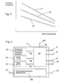
- Fig. 3 represented standard characteristic curve 30 - speed as a function of the burner power Q - is determined from the Lucasiereangins of the device with regard to condensation behavior, pollutant freedom and flame stability under standard conditions in laboratory experiments and stored as table 41 in the control electronics 7 ( Fig. 4 ).
- This standard characteristic 30 represents the course in which optimum emission values result under standard installation conditions. To determine the burner 16 is put into operation and varied the load over the entire modulation range. At each operating point, the speed is then determined, in which the CO and NO x emissions reach the required values, the over-ignition is still guaranteed and, secondly, no condensate is produced in the exhaust pipe.
- the operating characteristic curve is calculated from the standard characteristic curve by multiplying by the ratio "speed in pressure switch point" to "speed in pressure switch point under standard conditions". The latter is determined as the standard characteristic under standard conditions and stored in the memory 40 of the control electronics 7.
- Typical characteristics shows the Fig. 3 , wherein the standard characteristic 30 with the installation according to Fig. 2a correlates, the operating characteristic 31 with Fig. 2b and the operating characteristic 32 with Fig. 2c ,
- a heater 23 may be provided with differently shaped air-exhaust systems 24, which are formed by a fresh air supply 20 and an enclosed by this exhaust guide 11, and a blower 3.
- the air-exhaust system 24 angled ( Fig. 2a, 2b ) or straight ( Fig. 2c ).
- the length of the air exhaust system 24 can vary considerably ( Fig. 2a, 2b ), which results in significant differences in the flow resistance of the air-exhaust system 24.
- a correction factor is determined, with the operating characteristic curves 30 are determined from the stored in the control electronics 7 standard characteristics.
- the control of the modulating magnet 9 and thus the gas supply to the burner 16 and the rotational speed of the blower 3 is controlled by the control electronics 7 according to these operating characteristics.
- the control deviation is defined as the deviation of the actual flow temperature, measured by the temperature sensor 34 to the set target value, that of the controller 7 via the adjuster 43 is given.
- This adjuster 43 may be an outside temperature sensor, which is connected via a line 44 to a microprocessor uP of the controller 7, or a fixed value.
- the microprocessor ⁇ P has access to all tables via data lines 45, 46 and 47. Furthermore, the microprocessor ⁇ P is connected to all actual values and the nominal value transmitter via signal lines 33.
- controller 7 has a flame monitoring and ignition device 28, which is connected via lines 27 and 29 with a sensor, not shown, and an electrode, also not shown.
- the edge characteristics 31 and 32 set the highest and lowest speed, so that within the field between these limit characteristics safe burner operation is possible. Too high an excess of air would lead to a lifting of the flames and thus to an imperfect combustion and a too small air flow equally to incomplete combustion with carbon monoxide fractions.
- a correction factor is determined, with the operating characteristic curves are calculated from the stored in the controller 7 standard characteristics.
- the control of the modulating magnet 9 and thus the gas supply to the burner 16 and the rotational speed of the blower 3 is controlled by the controller 7 according to these operating characteristics.
- the fan 3 is kept for a certain minimum time, e.g. may be one minute, is operated at its maximum speed or power, whereby the temperature of the air volume flow at the pressure measuring system, the measured in the device measured flow temperature of the primary heat exchanger, so that depending on the measured flow and / or return temperature of the primary Heat exchanger can be closed to the temperature of the air flow.
- the speed of the fan 3 is lowered to the starting speed and then increased slowly until the intended pressure value is reached.
- a temperature correction function is calculated from the result of a measurement of the flow and / or return temperature of the primary heat exchanger 13, with the calculated speed from which a corrected speed is calculated, which is used to determine the operating characteristics.
Landscapes
- Engineering & Computer Science (AREA)
- Chemical & Material Sciences (AREA)
- Combustion & Propulsion (AREA)
- Mechanical Engineering (AREA)
- General Engineering & Computer Science (AREA)
- Regulation And Control Of Combustion (AREA)
- Air Supply (AREA)
- Chimneys And Flues (AREA)
- Sampling And Sample Adjustment (AREA)
Applications Claiming Priority (2)
| Application Number | Priority Date | Filing Date | Title |
|---|---|---|---|
| AT8002001 | 2001-05-21 | ||
| AT0080001A AT410477B (de) | 2001-05-21 | 2001-05-21 | Verfahren zur anpassung eines brennerbeheizten heizgerätes an ein luft-abgassystem |
Publications (3)
| Publication Number | Publication Date |
|---|---|
| EP1260766A2 EP1260766A2 (de) | 2002-11-27 |
| EP1260766A3 EP1260766A3 (de) | 2004-12-08 |
| EP1260766B1 true EP1260766B1 (de) | 2008-04-23 |
Family
ID=3681137
Family Applications (1)
| Application Number | Title | Priority Date | Filing Date |
|---|---|---|---|
| EP02010791A Expired - Lifetime EP1260766B1 (de) | 2001-05-21 | 2002-05-15 | Verfahren zur Anpassung eines brennerbeheizten Heizgerätes an ein Luft-Abgassystem |
Country Status (6)
| Country | Link |
|---|---|
| EP (1) | EP1260766B1 (da) |
| AT (2) | AT410477B (da) |
| DE (2) | DE10222770A1 (da) |
| DK (1) | DK1260766T3 (da) |
| ES (1) | ES2304408T3 (da) |
| PT (1) | PT1260766E (da) |
Families Citing this family (1)
| Publication number | Priority date | Publication date | Assignee | Title |
|---|---|---|---|---|
| DE102021109473A1 (de) * | 2021-04-15 | 2022-11-03 | Vaillant Gmbh | Verfahren zum Prüfen einer Abgasanlage eines Heizgerätes |
Family Cites Families (5)
| Publication number | Priority date | Publication date | Assignee | Title |
|---|---|---|---|---|
| DE19510425C2 (de) * | 1995-03-24 | 1999-05-27 | Bosch Gmbh Robert | Verfahren und Vorrichtung zur Regelung eines Heizgerätes |
| DE19607854A1 (de) * | 1996-03-01 | 1997-09-04 | Bosch Gmbh Robert | Heizgerät und Verfahren zur Regelung eines Heizgerätes |
| AT408033B (de) * | 1997-10-08 | 2001-08-27 | Vaillant Gmbh | Verfahren zur anpassung eines brennerbeheizten heizgerätes |
| DE19846207C2 (de) * | 1998-08-19 | 2000-10-26 | Wolf Gmbh | Vorrichtung und Verfahren zur Einstellung der Drehzahl eines Gebläses einer Gasheizeinrichtung, wie insbesondere einer Gastherme |
| DE19961285C1 (de) * | 1999-12-18 | 2001-06-28 | Bosch Gmbh Robert | Verfahren zum Regeln eines Wärmeerzeugers mit einer Luft-Abgas-Führung |
-
2001
- 2001-05-21 AT AT0080001A patent/AT410477B/de not_active IP Right Cessation
-
2002
- 2002-05-15 EP EP02010791A patent/EP1260766B1/de not_active Expired - Lifetime
- 2002-05-15 DE DE10222770A patent/DE10222770A1/de not_active Withdrawn
- 2002-05-15 DK DK02010791T patent/DK1260766T3/da active
- 2002-05-15 ES ES02010791T patent/ES2304408T3/es not_active Expired - Lifetime
- 2002-05-15 AT AT02010791T patent/ATE393361T1/de active
- 2002-05-15 PT PT02010791T patent/PT1260766E/pt unknown
- 2002-05-15 DE DE50212130T patent/DE50212130D1/de not_active Expired - Lifetime
Also Published As
| Publication number | Publication date |
|---|---|
| DK1260766T3 (da) | 2008-08-25 |
| EP1260766A3 (de) | 2004-12-08 |
| PT1260766E (pt) | 2008-07-07 |
| DE10222770A1 (de) | 2002-12-05 |
| DE50212130D1 (de) | 2008-06-05 |
| EP1260766A2 (de) | 2002-11-27 |
| ATE393361T1 (de) | 2008-05-15 |
| ATA8002001A (de) | 2002-09-15 |
| ES2304408T3 (es) | 2008-10-16 |
| AT410477B (de) | 2003-05-26 |
Similar Documents
| Publication | Publication Date | Title |
|---|---|---|
| EP2594848B1 (de) | Verfahren zur Steuerung einer Feuerungseinrichtung und Feuerungseinrichtung | |
| EP1761728B1 (de) | Verfahren zur einstellung der luftzahl an einer feuerungseinrichtung und feuerungseinrichtung | |
| DE3639172C2 (da) | ||
| DE3638410A1 (de) | Verfahren und vorrichtung zur regelung der luft- und brennstoffzufuhr zu einer vielzahl von brennern | |
| AT408033B (de) | Verfahren zur anpassung eines brennerbeheizten heizgerätes | |
| DE19635974A1 (de) | Gas/Luft-Mischsystem für Gasheizgeräte | |
| DE10109808C2 (de) | Verfahren und Vorrichtung zur Anpassung eines brennerbetriebenen Heizgerätes an ein Luft-Abgas-System | |
| EP0331918A2 (de) | Verfahren zum Betreiben eines Heizgeräts und Heizgerät | |
| EP1519113A2 (de) | Verfahren zur Anpassung der Geräteheizleistung eines gebläseunterstützten Heizgerätes an die individuellen Druckverluste eines Frischluft-Abgas-Leitungssystems | |
| EP1260766B1 (de) | Verfahren zur Anpassung eines brennerbeheizten Heizgerätes an ein Luft-Abgassystem | |
| EP1923634B1 (de) | Regelung des Brenngas-Luft-Gemisches über die Brenner- oder Flammentemperatur eines Heizgerätes | |
| DE102004055715C5 (de) | Verfahren zur Einstellung von Betriebsparametern an einer Feuerungseinrichtung und Feuerungseinrichtung | |
| EP1333227B1 (de) | Verfahren zur Anpassung eines brennerbeheizten Heizgerätes an ein diesem zugeordnetes Luft-/Abgassystem | |
| DE10140388C2 (de) | Heizgerät für mobile Anwendungen | |
| DE19652205C2 (de) | Brennersystem und Verfahren zum Betrieb eines Brenners | |
| DE102004063992B4 (de) | Verfahren zur Steuerung einer Feuerungseinrichtung und Feuerungseinrichtung | |
| DE3114942A1 (de) | Regeleinrichtung fuer den gasbefeuerten heizkessel einer warmwasser-heizungsanlage | |
| EP0036613B1 (de) | Durch einen Temperaturfühler steuerbare Regeleinrichtung für einen gasbefeuerten Wasser- oder Lufterhitzer | |
| EP1248044B1 (de) | Verfahren zur Inbetriebnahme eines Heizgerätes | |
| DE10144406C1 (de) | Heizgerät, insbesondere Zusatzheizgerät für mobile Anwendungen | |
| WO2008043347A1 (de) | Regelung einer heizleistung eines heizgeräts | |
| DE102004030300A1 (de) | Verfahren zur Einstellung eines Betriebsparameters einer Feuerungseinrichtung und Feuerungseinrichtung | |
| DE102022122811A1 (de) | Verfahren zum Betreiben eines Heizgerätes, Computerprogramm, Regel- und Steuer-gerät, Brennstoffdurchflussregler und Heizgerät | |
| DE202004017850U1 (de) | Feuerungseinrichtung | |
| EP1701096A1 (de) | Verfahren zur Anpassung der Geräteheizleistung eines gebläseunterstützten Heizgerätes an die individuellen Druckverluste eines Frischluft-Abgas-Leitungssystems |
Legal Events
| Date | Code | Title | Description |
|---|---|---|---|
| PUAI | Public reference made under article 153(3) epc to a published international application that has entered the european phase |
Free format text: ORIGINAL CODE: 0009012 |
|
| AK | Designated contracting states |
Kind code of ref document: A2 Designated state(s): AT BE CH CY DE DK ES FI FR GB GR IE IT LI LU MC NL PT SE TR |
|
| AX | Request for extension of the european patent |
Free format text: AL;LT;LV;MK;RO;SI |
|
| PUAL | Search report despatched |
Free format text: ORIGINAL CODE: 0009013 |
|
| AK | Designated contracting states |
Kind code of ref document: A3 Designated state(s): AT BE CH CY DE DK ES FI FR GB GR IE IT LI LU MC NL PT SE TR |
|
| AX | Request for extension of the european patent |
Extension state: AL LT LV MK RO SI |
|
| 17P | Request for examination filed |
Effective date: 20050519 |
|
| AKX | Designation fees paid |
Designated state(s): AT BE CH CY DE DK ES FI FR GB GR IE IT LI LU MC NL PT SE TR |
|
| GRAP | Despatch of communication of intention to grant a patent |
Free format text: ORIGINAL CODE: EPIDOSNIGR1 |
|
| GRAS | Grant fee paid |
Free format text: ORIGINAL CODE: EPIDOSNIGR3 |
|
| GRAA | (expected) grant |
Free format text: ORIGINAL CODE: 0009210 |
|
| AK | Designated contracting states |
Kind code of ref document: B1 Designated state(s): AT BE CH CY DE DK ES FI FR GB GR IE IT LI LU MC NL PT SE TR |
|
| REG | Reference to a national code |
Ref country code: GB Ref legal event code: FG4D Free format text: NOT ENGLISH |
|
| REG | Reference to a national code |
Ref country code: CH Ref legal event code: EP |
|
| REF | Corresponds to: |
Ref document number: 50212130 Country of ref document: DE Date of ref document: 20080605 Kind code of ref document: P |
|
| REG | Reference to a national code |
Ref country code: IE Ref legal event code: FG4D Free format text: LANGUAGE OF EP DOCUMENT: GERMAN |
|
| REG | Reference to a national code |
Ref country code: PT Ref legal event code: SC4A Free format text: AVAILABILITY OF NATIONAL TRANSLATION Effective date: 20080625 |
|
| REG | Reference to a national code |
Ref country code: DK Ref legal event code: T3 |
|
| REG | Reference to a national code |
Ref country code: ES Ref legal event code: FG2A Ref document number: 2304408 Country of ref document: ES Kind code of ref document: T3 |
|
| PG25 | Lapsed in a contracting state [announced via postgrant information from national office to epo] |
Ref country code: FI Free format text: LAPSE BECAUSE OF FAILURE TO SUBMIT A TRANSLATION OF THE DESCRIPTION OR TO PAY THE FEE WITHIN THE PRESCRIBED TIME-LIMIT Effective date: 20080423 |
|
| BERE | Be: lapsed |
Owner name: VAILLANT G.M.B.H. Effective date: 20080531 |
|
| REG | Reference to a national code |
Ref country code: IE Ref legal event code: FD4D |
|
| PG25 | Lapsed in a contracting state [announced via postgrant information from national office to epo] |
Ref country code: MC Free format text: LAPSE BECAUSE OF NON-PAYMENT OF DUE FEES Effective date: 20080531 |
|
| PG25 | Lapsed in a contracting state [announced via postgrant information from national office to epo] |
Ref country code: IE Free format text: LAPSE BECAUSE OF FAILURE TO SUBMIT A TRANSLATION OF THE DESCRIPTION OR TO PAY THE FEE WITHIN THE PRESCRIBED TIME-LIMIT Effective date: 20080423 Ref country code: SE Free format text: LAPSE BECAUSE OF FAILURE TO SUBMIT A TRANSLATION OF THE DESCRIPTION OR TO PAY THE FEE WITHIN THE PRESCRIBED TIME-LIMIT Effective date: 20080723 |
|
| EN | Fr: translation not filed | ||
| PLBE | No opposition filed within time limit |
Free format text: ORIGINAL CODE: 0009261 |
|
| STAA | Information on the status of an ep patent application or granted ep patent |
Free format text: STATUS: NO OPPOSITION FILED WITHIN TIME LIMIT |
|
| GBPC | Gb: european patent ceased through non-payment of renewal fee |
Effective date: 20080723 |
|
| PG25 | Lapsed in a contracting state [announced via postgrant information from national office to epo] |
Ref country code: BE Free format text: LAPSE BECAUSE OF NON-PAYMENT OF DUE FEES Effective date: 20080531 |
|
| 26N | No opposition filed |
Effective date: 20090126 |
|
| PG25 | Lapsed in a contracting state [announced via postgrant information from national office to epo] |
Ref country code: GB Free format text: LAPSE BECAUSE OF NON-PAYMENT OF DUE FEES Effective date: 20080723 |
|
| PG25 | Lapsed in a contracting state [announced via postgrant information from national office to epo] |
Ref country code: LU Free format text: LAPSE BECAUSE OF NON-PAYMENT OF DUE FEES Effective date: 20080515 Ref country code: CY Free format text: LAPSE BECAUSE OF FAILURE TO SUBMIT A TRANSLATION OF THE DESCRIPTION OR TO PAY THE FEE WITHIN THE PRESCRIBED TIME-LIMIT Effective date: 20080423 |
|
| PG25 | Lapsed in a contracting state [announced via postgrant information from national office to epo] |
Ref country code: GR Free format text: LAPSE BECAUSE OF FAILURE TO SUBMIT A TRANSLATION OF THE DESCRIPTION OR TO PAY THE FEE WITHIN THE PRESCRIBED TIME-LIMIT Effective date: 20080724 |
|
| PG25 | Lapsed in a contracting state [announced via postgrant information from national office to epo] |
Ref country code: FR Free format text: LAPSE BECAUSE OF FAILURE TO SUBMIT A TRANSLATION OF THE DESCRIPTION OR TO PAY THE FEE WITHIN THE PRESCRIBED TIME-LIMIT Effective date: 20090227 |
|
| PGFP | Annual fee paid to national office [announced via postgrant information from national office to epo] |
Ref country code: CH Payment date: 20150508 Year of fee payment: 14 Ref country code: DK Payment date: 20150508 Year of fee payment: 14 |
|
| PGFP | Annual fee paid to national office [announced via postgrant information from national office to epo] |
Ref country code: AT Payment date: 20150506 Year of fee payment: 14 |
|
| REG | Reference to a national code |
Ref country code: CH Ref legal event code: PL |
|
| REG | Reference to a national code |
Ref country code: DK Ref legal event code: EBP Effective date: 20160531 |
|
| REG | Reference to a national code |
Ref country code: NL Ref legal event code: MM Effective date: 20160601 |
|
| REG | Reference to a national code |
Ref country code: AT Ref legal event code: MM01 Ref document number: 393361 Country of ref document: AT Kind code of ref document: T Effective date: 20160515 |
|
| PG25 | Lapsed in a contracting state [announced via postgrant information from national office to epo] |
Ref country code: LI Free format text: LAPSE BECAUSE OF NON-PAYMENT OF DUE FEES Effective date: 20160531 Ref country code: CH Free format text: LAPSE BECAUSE OF NON-PAYMENT OF DUE FEES Effective date: 20160531 |
|
| PG25 | Lapsed in a contracting state [announced via postgrant information from national office to epo] |
Ref country code: NL Free format text: LAPSE BECAUSE OF NON-PAYMENT OF DUE FEES Effective date: 20160601 Ref country code: AT Free format text: LAPSE BECAUSE OF NON-PAYMENT OF DUE FEES Effective date: 20160515 |
|
| PG25 | Lapsed in a contracting state [announced via postgrant information from national office to epo] |
Ref country code: DK Free format text: LAPSE BECAUSE OF NON-PAYMENT OF DUE FEES Effective date: 20160531 |
|
| PGFP | Annual fee paid to national office [announced via postgrant information from national office to epo] |
Ref country code: NL Payment date: 20170531 Year of fee payment: 16 |
|
| PGFP | Annual fee paid to national office [announced via postgrant information from national office to epo] |
Ref country code: PT Payment date: 20180507 Year of fee payment: 17 Ref country code: ES Payment date: 20180618 Year of fee payment: 17 Ref country code: DE Payment date: 20180430 Year of fee payment: 17 |
|
| PGFP | Annual fee paid to national office [announced via postgrant information from national office to epo] |
Ref country code: IT Payment date: 20180531 Year of fee payment: 17 Ref country code: TR Payment date: 20180514 Year of fee payment: 17 |
|
| REG | Reference to a national code |
Ref country code: NL Ref legal event code: MM Effective date: 20180601 |
|
| PG25 | Lapsed in a contracting state [announced via postgrant information from national office to epo] |
Ref country code: NL Free format text: LAPSE BECAUSE OF NON-PAYMENT OF DUE FEES Effective date: 20180601 |
|
| REG | Reference to a national code |
Ref country code: NL Ref legal event code: MM Effective date: 20180601 |
|
| REG | Reference to a national code |
Ref country code: DE Ref legal event code: R119 Ref document number: 50212130 Country of ref document: DE |
|
| PG25 | Lapsed in a contracting state [announced via postgrant information from national office to epo] |
Ref country code: PT Free format text: LAPSE BECAUSE OF NON-PAYMENT OF DUE FEES Effective date: 20191115 |
|
| PG25 | Lapsed in a contracting state [announced via postgrant information from national office to epo] |
Ref country code: IT Free format text: LAPSE BECAUSE OF NON-PAYMENT OF DUE FEES Effective date: 20190515 Ref country code: DE Free format text: LAPSE BECAUSE OF NON-PAYMENT OF DUE FEES Effective date: 20191203 |
|
| REG | Reference to a national code |
Ref country code: ES Ref legal event code: FD2A Effective date: 20200925 |
|
| PG25 | Lapsed in a contracting state [announced via postgrant information from national office to epo] |
Ref country code: ES Free format text: LAPSE BECAUSE OF NON-PAYMENT OF DUE FEES Effective date: 20190516 |
|
| PG25 | Lapsed in a contracting state [announced via postgrant information from national office to epo] |
Ref country code: TR Free format text: LAPSE BECAUSE OF NON-PAYMENT OF DUE FEES Effective date: 20190515 |