EP1261065A2 - Thermische Verwaltung mittels Abdeckung und Ummantlung von Batteriesystemmodulen - Google Patents
Thermische Verwaltung mittels Abdeckung und Ummantlung von Batteriesystemmodulen Download PDFInfo
- Publication number
- EP1261065A2 EP1261065A2 EP02291212A EP02291212A EP1261065A2 EP 1261065 A2 EP1261065 A2 EP 1261065A2 EP 02291212 A EP02291212 A EP 02291212A EP 02291212 A EP02291212 A EP 02291212A EP 1261065 A2 EP1261065 A2 EP 1261065A2
- Authority
- EP
- European Patent Office
- Prior art keywords
- thermal
- management system
- liquid
- cells
- thermal management
- Prior art date
- Legal status (The legal status is an assumption and is not a legal conclusion. Google has not performed a legal analysis and makes no representation as to the accuracy of the status listed.)
- Withdrawn
Links
Images


Classifications
-
- H—ELECTRICITY
- H01—ELECTRIC ELEMENTS
- H01M—PROCESSES OR MEANS, e.g. BATTERIES, FOR THE DIRECT CONVERSION OF CHEMICAL ENERGY INTO ELECTRICAL ENERGY
- H01M10/00—Secondary cells; Manufacture thereof
- H01M10/60—Heating or cooling; Temperature control
- H01M10/61—Types of temperature control
- H01M10/613—Cooling or keeping cold
-
- H—ELECTRICITY
- H01—ELECTRIC ELEMENTS
- H01M—PROCESSES OR MEANS, e.g. BATTERIES, FOR THE DIRECT CONVERSION OF CHEMICAL ENERGY INTO ELECTRICAL ENERGY
- H01M10/00—Secondary cells; Manufacture thereof
- H01M10/60—Heating or cooling; Temperature control
- H01M10/61—Types of temperature control
- H01M10/615—Heating or keeping warm
-
- H—ELECTRICITY
- H01—ELECTRIC ELEMENTS
- H01M—PROCESSES OR MEANS, e.g. BATTERIES, FOR THE DIRECT CONVERSION OF CHEMICAL ENERGY INTO ELECTRICAL ENERGY
- H01M10/00—Secondary cells; Manufacture thereof
- H01M10/60—Heating or cooling; Temperature control
- H01M10/64—Heating or cooling; Temperature control characterised by the shape of the cells
- H01M10/643—Cylindrical cells
-
- H—ELECTRICITY
- H01—ELECTRIC ELEMENTS
- H01M—PROCESSES OR MEANS, e.g. BATTERIES, FOR THE DIRECT CONVERSION OF CHEMICAL ENERGY INTO ELECTRICAL ENERGY
- H01M10/00—Secondary cells; Manufacture thereof
- H01M10/60—Heating or cooling; Temperature control
- H01M10/65—Means for temperature control structurally associated with the cells
- H01M10/655—Solid structures for heat exchange or heat conduction
- H01M10/6556—Solid parts with flow channel passages or pipes for heat exchange
- H01M10/6557—Solid parts with flow channel passages or pipes for heat exchange arranged between the cells
-
- H—ELECTRICITY
- H01—ELECTRIC ELEMENTS
- H01M—PROCESSES OR MEANS, e.g. BATTERIES, FOR THE DIRECT CONVERSION OF CHEMICAL ENERGY INTO ELECTRICAL ENERGY
- H01M10/00—Secondary cells; Manufacture thereof
- H01M10/60—Heating or cooling; Temperature control
- H01M10/65—Means for temperature control structurally associated with the cells
- H01M10/656—Means for temperature control structurally associated with the cells characterised by the type of heat-exchange fluid
- H01M10/6567—Liquids
-
- H—ELECTRICITY
- H01—ELECTRIC ELEMENTS
- H01M—PROCESSES OR MEANS, e.g. BATTERIES, FOR THE DIRECT CONVERSION OF CHEMICAL ENERGY INTO ELECTRICAL ENERGY
- H01M10/00—Secondary cells; Manufacture thereof
- H01M10/60—Heating or cooling; Temperature control
- H01M10/62—Heating or cooling; Temperature control specially adapted for specific applications
- H01M10/625—Vehicles
-
- H—ELECTRICITY
- H01—ELECTRIC ELEMENTS
- H01M—PROCESSES OR MEANS, e.g. BATTERIES, FOR THE DIRECT CONVERSION OF CHEMICAL ENERGY INTO ELECTRICAL ENERGY
- H01M50/00—Constructional details or processes of manufacture of the non-active parts of electrochemical cells other than fuel cells, e.g. hybrid cells
- H01M50/20—Mountings; Secondary casings or frames; Racks, modules or packs; Suspension devices; Shock absorbers; Transport or carrying devices; Holders
- H01M50/204—Racks, modules or packs for multiple batteries or multiple cells
- H01M50/207—Racks, modules or packs for multiple batteries or multiple cells characterised by their shape
- H01M50/213—Racks, modules or packs for multiple batteries or multiple cells characterised by their shape adapted for cells having curved cross-section, e.g. round or elliptic
-
- H—ELECTRICITY
- H01—ELECTRIC ELEMENTS
- H01M—PROCESSES OR MEANS, e.g. BATTERIES, FOR THE DIRECT CONVERSION OF CHEMICAL ENERGY INTO ELECTRICAL ENERGY
- H01M6/00—Primary cells; Manufacture thereof
- H01M6/42—Grouping of primary cells into batteries
-
- Y—GENERAL TAGGING OF NEW TECHNOLOGICAL DEVELOPMENTS; GENERAL TAGGING OF CROSS-SECTIONAL TECHNOLOGIES SPANNING OVER SEVERAL SECTIONS OF THE IPC; TECHNICAL SUBJECTS COVERED BY FORMER USPC CROSS-REFERENCE ART COLLECTIONS [XRACs] AND DIGESTS
- Y02—TECHNOLOGIES OR APPLICATIONS FOR MITIGATION OR ADAPTATION AGAINST CLIMATE CHANGE
- Y02E—REDUCTION OF GREENHOUSE GAS [GHG] EMISSIONS, RELATED TO ENERGY GENERATION, TRANSMISSION OR DISTRIBUTION
- Y02E60/00—Enabling technologies; Technologies with a potential or indirect contribution to GHG emissions mitigation
- Y02E60/10—Energy storage using batteries
Definitions
- the present invention generally relates to the field of electrochemical batteries, in particular a thermal management system for controlling or managing the temperature of individual electrochemical cells within the modules of a battery system.
- electrochemical batteries are used in many applications such as electrical vehicles, industrial systems, etc. When these batteries are used in these applications they are required to provide a large amount of energy and power. In doing so they generate large amounts of heat. Additionally, in these applications batteries are required to function in less than perfect conditions for efficient battery usage. This is because the environment can be too cold or too hot for efficient battery use.
- the present invention is intended to overcome one or more of the above problems.
- the present invention is a thermal blanketing or tubular system used to manage the temperature of electrochemical cells within the modules of a single battery system.
- the present invention uses either a thin walled tube made from a flexible or rigid material (i.e. plastic, etc.) which is wound in a fashion so at least one side of the tube makes contact with each individual cell, or uses a plurality of individual thermal jackets placed between battery cells such that at least some of the thermal jackets are contacted by at least two of the cells within the battery.
- each tube or jacket is filled with a thermal management fluid, chosen for its thermal management characteristics, and which flows through the tube or jackets, and acts either as a heat sink absorbing heat from the cells to cool them, or as a heat source providing heat to the batteries as needed.
- a thermal management fluid chosen for its thermal management characteristics, and which flows through the tube or jackets, and acts either as a heat sink absorbing heat from the cells to cool them, or as a heat source providing heat to the batteries as needed.
- Each tube or jacket has an inlet and exit manifold to allow the fluid to flow, and a pump or flow manifold is used to provide the flow and maintain pressure within the tubing or jackets.
- the walls of the electrochemical cells and the tube or jacket be made of a material conducive to allowing the transfer of heat easily and efficiently. Additionally, it is also preferable to provide an efficient thermal medium between the tube and the cell, to aid in the thermal transfer between tube and cell. Finally, in the preferred embodiment of the present invention, a thermal exchanger or unit which would either heat or cool the fluid may be used to provide more efficient and effective thermal management of the battery and cells.
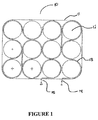
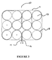
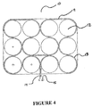
- FIGS 1-4 depict an electrochemical battery 10 with twelve individual cells 12 and a thermal blanket or tube 13 according to the first embodiment of the present invention. It should be noted that the present invention can be used with batteries having any number of cells, and is not limited to twelve cell batteries.
- FIGs 1-4 show that the thermal blanket or tube 13 makes contact with each of the individual cells 12 as it winds through the battery casing 11. Further, it can be seen in these figures that many different types of winding configurations of the blanket or tube 13 can be used, and the present invention is not limited to the embodiments shown in the Figures.
- the blanket or tube 13 has both an entrance manifold 14 and an exit manifold 15. This is to allow for flow of the thermally conductive liquid (not shown) to be used in the blanket 13 to control the temperatures of the cells 12 and thus the battery 10. It is desirable to have as much of the cell 12 surfaces covered by the tube or blanket 13 to provide as large a thermally conductive surface as reasonably possible. This will allow optimization of the thermal control process.
- the module design, cell configuration and desired (or actual) operating temperature difference from cell to cell will dictate the amount of contact between the cell surfaces and the thermal blanket or tube 13.
- the blanket or tube 13 is sized to cover as much of the length of the cell (i.e. height of the cell) as possible between the cell boards or cell support structure (not shown).
- the thickness of the tube or blanket 13 walls is to be as thin as possible for the material used for the blanket. This is to ensure that the best possible heat transfer characteristics between the cells and the thermal medium used in the tube or blanket.
- the heat transfer optimization must be balanced with the need for having a wall thickness large enough to ensure proper manufacturing of the of the tube at a reasonable cost, and to prevent the seepage or leaking of the thermal liquid from the tube or blanket 13.
- the optimal thickness will vary depending on the material to be used.
- the tube or blanket 13 may be manufactured from any material suitable for this purpose, i.e. metal, plastic, etc. However, it is desirable that the blanket or tube 13 be made from a material that is thermally conductive to allow the transfer of heat to or from the thermal liquid passing through the tube or blanket. Further, the material can either be flexible or rigid depending on the manufacturing capabilities or needs.
- the cross-sectional shape of the tube or blanket 13 can be any shape conducive to allowing proper thermal management of the individual cells 12 in the battery 10.
- the preferred cross-section of the tube 13 would be rectangular. This will allow maximum surface contact between both the cells 12 and the blanket 13.
- the shape can be changed depending on the configuration and shape of the cells and battery, and may be optimized for each different battery configuration.
- the cross-section shape or size can change in the tube or blanket 13 used in a battery. This would allow for manufacture optimization.
- the shape of the cross-section of a single tube is to change along its length, the change should not be significant so as to adversely affect the proper flow of the liquid within the tube.
- a thermally conductive material or medium 16 could be placed between the blanket 13 and cells 12. See Figure 9, showing a close-up view of a single cell 12 of the present invention with a thermal medium 16 placed between the cell and the tube 13.
- An example of this material would be thermally conductive grease.
- the tube or blanket is made from a thermally conductive plastic material it is important that the grease used be mainly thermally conductive and have little or no capability of conducting electricity. This material enhances the thermal conductance between the cells and the blanket or tube.
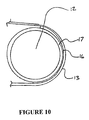
- a metallic thermally conductive material is used for the tube or blanket it is important to have an electrical insulating material 17 between the tube 13 and the cell 12, to prevent the unnecessary transfer of electricity between cells though the tube or blanket 13. See Figure 10, which shows a cell 12 having a insulating material 17, a thermal conductive medium 16 and the tube 13. This electrical insulation can be achieved by using any shrink-sleeve type material commonly used to insulate electrochemical cells.
- Each of the intake and exit manifolds 14, 15 allows for flow of the thermally managing liquid through the tube 13.
- the manifolds 14, 15 are connected to a fluid flow manifold or device such as a pump (not shown) which would be used to provide the flow of the liquid through the tube.
- a fluid flow manifold or device such as a pump (not shown) which would be used to provide the flow of the liquid through the tube.
- Any type of thermally conductive liquid can be used, however, it is important to ensure that the liquid used would not deteriorate the tube or blanket walls.
- Any commonly known or used flow manifold, flowing device, or pump can be used to provide the fluid flow through the tube.
- the fluid flow device will provide enough flow to ensure that a slight internal pressure is maintained within the tube to aid in maintain the flow of the liquid while at the same time preventing the walls of the tube or blanket 13 from collapsing.
- Tube collapse could also be prevented by using additional structural support within the tube, such as ribs (not shown), or providing additional tube wall reinforcement (not shown). If internal ribs are used they should be configured such that they do not adversely interfere with the liquid flow to ensure optimal thermal management.
- the tube or blanket 13 would be connected to a liquid heater/cooler to provide thermal control of the battery by controlling the temperature of the liquid. It is desirable to have this capability within the flow manifold, or pump, to reduce the number of components and space, but it is not necessary to the present invention. Further, depending on the application of the battery it may not be necessary to have both heating and cooling capability, but only one or the other. For instance, if the battery is used in a environment having continuous high temperatures, a heating capability would not be necessary.
- one or more loops of the tube or blanket 13 may be required depending on the number of cells/rows of cells per module. If more than one loop is used, each of the individual loops can be connected to the same flow manifold to maintain even flow distribution. Further, it may be desirable to use more than one blanket in a single cell module to provide added thermal control or redundancy. In this configuration there could be two blankets 13 each covering one half of the height of the cells. In this configuration the blankets could be connected to the same or separate exit/entrance manifolds and flow manifolds depending on whether or not complete redundance is needed.
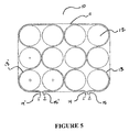
- FIG. 5 depicts an alternate configuration of the first embodiment of the present invention, where there are two blankets or tubes 13, 13', each thermally managing half of the cells 12 in the module 10.
- the blankets 13, 13' are shown with their own exit/entrance manifolds 14, 15 and 14', 15', respectively, but it is also possible to have each of the blankets 13, 13' connected to the same manifold, depending on the type of protection needed.
- the blankets can be connected to a separate flow manifold and heating/cooling apparatus depending on the system requirements and space constraints.
- the number of blankets contemplated by this invention is not limited to two, but can be any number required or practical for the particular battery and cell configuration.
- the thermal management liquid used in the present invention can be any commonly known or used liquid that is known to have thermal management characteristics.
- the liquid used rapidly absorbs or transfers heat from either the cells or the heater/cooler and/or rapidly cools down after being heated. Further, if excessive or extreme temperatures (either hot or cold) are to be experienced then this should be taken into account when choosing the liquid. The liquid should not break down or otherwise lose its thermal managing characteristics at extreme temperatures.
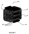
- FIGS 6A to 8 depict a second embodiment of the present invention, where instead of winding tubes, there is a plurality of thermal jackets 50 used and positioned between the cells 12.
- the manufacture of the thermal jackets 50 in this embodiment may be similar to that discussed above with regard to the tube or jacket 13 of the previous embodiment.
- the materials used may be the same, and optimized for thermal control.
- the jacket 50 is not a winding blanket, but can be a straight hollow member having both an intake manifold 52 and an exit manifold 51 to allow the passage of the thermal management liquid.
- the jacket in Figures 6A and 6B is shown as being straight, it may have bends or be otherwise configured to be adapted to specific battery or cell configurations, for example having a 90 degree bend.
- the jacket 50 has a plurality of radiused depressions 53 which are configured to snugly receive the cells 12 in the battery, and are adjacent to raised portions 54.
- the shape and contour of the depressions 53 are configured to match the shape or configuration of the cells to ensure maximum surface contact, resulting in maximum efficiency of the thermal protection system.
- Figure 7 shows a typical nine cell electrochemical battery module 100, having two cell supports 101, with the two thermal jackets 50, of the second embodiment of the present invention, positioned on the outside edges of the outer cells and two jackets 50 between the three rows of cells 12.
- the second embodiment can be used with any type of battery/cell configuration. It is not necessary that the jackets 50 be of the same length or size and they can be modified to adapt to any battery or cell configuration.
- thermally conductive grease or other medium
- the type of material used for the jacket walls will dictate the type of thermal medium to be used between the cells and the jacket.
- the jackets can either be connected to individual flow manifolds or to a common flow manifold. If the jackets are connected to a common manifold they can be connected in either parallel or in series depending on the preferred configuration. In either configuration it is desirable to maintain constant flow and pressure to ensure proper and even thermal management of the battery and cells.
- all of the jackets may be connected through a common manifold to a flow manifold and heater/cooler or may be divided among two or more redundant or independent systems.
Landscapes
- Engineering & Computer Science (AREA)
- Manufacturing & Machinery (AREA)
- Chemical & Material Sciences (AREA)
- Chemical Kinetics & Catalysis (AREA)
- Electrochemistry (AREA)
- General Chemical & Material Sciences (AREA)
- Secondary Cells (AREA)
- Sealing Battery Cases Or Jackets (AREA)
Applications Claiming Priority (2)
| Application Number | Priority Date | Filing Date | Title |
|---|---|---|---|
| US09/862,591 US20020177035A1 (en) | 2001-05-23 | 2001-05-23 | Thermal management blanketing and jacketing for battery system modules |
| US862591 | 2001-05-23 |
Publications (2)
| Publication Number | Publication Date |
|---|---|
| EP1261065A2 true EP1261065A2 (de) | 2002-11-27 |
| EP1261065A3 EP1261065A3 (de) | 2004-03-10 |
Family
ID=25338815
Family Applications (1)
| Application Number | Title | Priority Date | Filing Date |
|---|---|---|---|
| EP02291212A Withdrawn EP1261065A3 (de) | 2001-05-23 | 2002-05-16 | Thermische Verwaltung mittels Abdeckung und Ummantlung von Batteriesystemmodulen |
Country Status (2)
| Country | Link |
|---|---|
| US (1) | US20020177035A1 (de) |
| EP (1) | EP1261065A3 (de) |
Cited By (17)
| Publication number | Priority date | Publication date | Assignee | Title |
|---|---|---|---|---|
| GB2387019A (en) * | 2002-03-30 | 2003-10-01 | Bosch Gmbh Robert | Energy storage module and electrical device |
| EP1746672A2 (de) | 2005-07-22 | 2007-01-24 | Saft | Vorrichtung zur thermischen regelung |
| WO2007087665A3 (de) * | 2006-02-01 | 2007-10-11 | Magna Steyr Fahrzeugtechnik Ag | Hochleistungsbatterie mit kühlung |
| EP2079125A2 (de) | 2008-01-08 | 2009-07-15 | Saft Groupe S.A. | Verfahren zur Steuerung des Aufladevorgangs einer Batterie |
| WO2011110483A1 (de) * | 2010-03-08 | 2011-09-15 | Behr Gmbh & Co. Kg | Kühlvorrichtung für eine elektrochemische energiespeichereinheit und herstellungsverfahren für eine kühlvorrichtung |
| US8076019B2 (en) | 2002-03-30 | 2011-12-13 | Robert Bosch Gmbh | Energy storage module and electrical apparatus |
| EP3046178A1 (de) | 2015-01-15 | 2016-07-20 | Saft | Batterie, die mit einer vorrichtung zur wärmeregulierung der elektrochemischen elemente ausgestattet ist, und entsprechendes herstellungsverfahren |
| AT520409A1 (de) * | 2017-09-05 | 2019-03-15 | Miba Ag | Akkumulator |
| WO2019129734A1 (fr) | 2017-12-27 | 2019-07-04 | Saft | Couvercle d'element electrochimique a conduction thermique renforcee |
| AT521295A1 (de) * | 2018-06-12 | 2019-12-15 | Miba Ag | Akkumulator |
| CN111544803A (zh) * | 2020-02-28 | 2020-08-18 | 青岛能蜂电气有限公司 | 一种自动灭火装置 |
| US11296368B2 (en) | 2017-06-13 | 2022-04-05 | Miba Emobility Gmbh | Rechargeable battery comprising a cooling device |
| US11444342B2 (en) | 2017-07-03 | 2022-09-13 | Miba Emobility Gmbh | Storage battery comprising a cooling device connected to the bus bar |
| US11637337B2 (en) | 2017-09-14 | 2023-04-25 | Miba Emobility Gmbh | Accumulator |
| AT525841A1 (de) * | 2022-02-04 | 2023-08-15 | Fiberdraft E U | Vorrichtung und Verfahren zur Herstellung von Energiespeichermodulen mit Distanzhalteband |
| EP4258420A4 (de) * | 2022-01-13 | 2024-03-13 | Contemporary Amperex Technology Co., Limited | Batterie, stromverbrauchsvorrichtung, verfahren und vorrichtung zur herstellung der batterie |
| US12519153B2 (en) | 2017-09-14 | 2026-01-06 | Miba Emobility Gmbh | Accumulator |
Families Citing this family (53)
| Publication number | Priority date | Publication date | Assignee | Title |
|---|---|---|---|---|
| DE10034134A1 (de) * | 2000-07-13 | 2002-01-31 | Daimler Chrysler Ag | Wärmetauscherstruktur für mehrere elektrochemische Speicherzellen |
| US7045236B1 (en) | 2001-08-10 | 2006-05-16 | Johnson Controls Technology Company | Heat and gas exchange system for battery |
| DE10151604A1 (de) * | 2001-10-18 | 2003-04-30 | Nbt Gmbh | Akkumulatorenbatterie |
| US7510797B2 (en) * | 2005-02-24 | 2009-03-31 | Aker Wade Power Technologies, Llc | High capacity battery with integrally-powered cooling assembly |
| US20070218353A1 (en) * | 2005-05-12 | 2007-09-20 | Straubel Jeffrey B | System and method for inhibiting the propagation of an exothermic event |
| US20070009787A1 (en) * | 2005-05-12 | 2007-01-11 | Straubel Jeffrey B | Method and apparatus for mounting, cooling, connecting and protecting batteries |
| CA2538817C (en) * | 2006-03-08 | 2010-05-18 | Psion Teklogix Inc. | Insulated smart battery pack for low temperature applications |
| US7531270B2 (en) * | 2006-10-13 | 2009-05-12 | Enerdel, Inc. | Battery pack with integral cooling and bussing devices |
| KR101047942B1 (ko) * | 2007-02-01 | 2011-07-12 | 주식회사 엘지화학 | 냉매 순환식 노트북 컴퓨터용 전지팩 |
| DE102007021293A1 (de) * | 2007-05-07 | 2008-11-13 | Valeo Klimasysteme Gmbh | Antriebsbatteriebaugruppe eines Elektro-, Brennstoffzellen- oder Hybridfahrzeugs |
| US20080292948A1 (en) * | 2007-05-23 | 2008-11-27 | Ajith Kuttannair Kumar | Battery cooling system and methods of cooling |
| US20090023056A1 (en) * | 2007-07-18 | 2009-01-22 | Tesla Motors, Inc. | Battery pack thermal management system |
| WO2009061451A1 (en) * | 2007-11-07 | 2009-05-14 | Enerdel, Inc. | Battery assembly with temperature control device |
| DE102008009041A1 (de) * | 2008-02-14 | 2009-08-20 | Valeo Klimasysteme Gmbh | Antriebsbatteriebaugruppe eines Elektro-, Brennstoffzellen- oder Hybridfahrzeugs |
| DE102008032086A1 (de) * | 2008-07-08 | 2010-01-14 | Valeo Klimasysteme Gmbh | Antriebsbatteriebaugruppe eines Elektro-, Brennstoffzellen- oder Hybridfahrzeugs |
| CN102257652B (zh) | 2008-11-12 | 2014-04-02 | 江森自控帅福得先进能源动力系统有限责任公司 | 具有热交换器的电池系统 |
| US20110048062A1 (en) * | 2009-03-25 | 2011-03-03 | Thomas Gielda | Portable Cooling Unit |
| US8820114B2 (en) | 2009-03-25 | 2014-09-02 | Pax Scientific, Inc. | Cooling of heat intensive systems |
| US20110048048A1 (en) * | 2009-03-25 | 2011-03-03 | Thomas Gielda | Personal Cooling System |
| US8505322B2 (en) * | 2009-03-25 | 2013-08-13 | Pax Scientific, Inc. | Battery cooling |
| KR20120093060A (ko) | 2009-03-25 | 2012-08-22 | 카이틴, 아이엔씨. | 초음파 냉각 시스템 |
| KR101352659B1 (ko) * | 2009-06-08 | 2014-01-16 | 주식회사 엘지화학 | 히트파이프가 구비된 노트북 컴퓨터용 배터리팩 |
| CN102511091B (zh) | 2009-06-18 | 2014-09-24 | 江森自控帅福得先进能源动力系统有限责任公司 | 具有带有热管理部件的电池单元托盘的电池模块 |
| US20110051549A1 (en) * | 2009-07-25 | 2011-03-03 | Kristian Debus | Nucleation Ring for a Central Insert |
| US8365540B2 (en) | 2009-09-04 | 2013-02-05 | Pax Scientific, Inc. | System and method for heat transfer |
| KR101093695B1 (ko) | 2009-10-16 | 2011-12-19 | 삼성에스디아이 주식회사 | 전지 모듈 |
| US8765282B2 (en) * | 2009-12-18 | 2014-07-01 | GM Global Technology Operations LLC | Battery assemblies |
| US9350002B2 (en) | 2010-07-01 | 2016-05-24 | Johnson Controls—SAFT Advanced Power Solutions LLC | Thermal management of a battery system |
| US9653762B2 (en) * | 2010-08-12 | 2017-05-16 | Furukawa Electric Co., Ltd. | Battery temperature regulation system and battery temperature regulation unit |
| EP2672544B1 (de) * | 2012-06-04 | 2020-05-20 | EaglePicher Technologies, LLC | Konturiertes batteriegehäuse auf grundlage der zellenformen |
| US9415673B2 (en) | 2014-06-30 | 2016-08-16 | Faster Faster Inc. | Integrated chassis heatsink for electric vehicles |
| EP3062381B1 (de) * | 2015-02-26 | 2018-04-11 | Magneti Marelli S.p.A. | Kühlkreislauf mit kühlflüssigkeit für lithiumbatterien und fahrzeug mit dem kühlkreislauf |
| WO2017065762A1 (en) * | 2015-10-14 | 2017-04-20 | Covestro Llc | Phosphazene modified polycarbonate molded battery cooling device |
| CN106785236B (zh) * | 2015-11-23 | 2023-05-12 | 赵耀华 | 圆柱体电池组的热管理系统和方法 |
| FR3050326B1 (fr) * | 2016-04-14 | 2021-12-24 | Accumulateurs Fixes | Assemblage d'elements electrochimiques par un procede de fabrication additive |
| GB2549512C (en) * | 2016-04-20 | 2022-01-12 | Delta Motorsport Ltd | Cell pack thermal management apparatus and method |
| US10116016B2 (en) * | 2016-05-23 | 2018-10-30 | Borgwarner Inc. | Thermal management system and method of making and using the same |
| US11588214B2 (en) | 2017-01-27 | 2023-02-21 | Cps Technology Holdings Llc | Battery straps |
| EP3635805B1 (de) | 2017-06-09 | 2023-09-06 | CPS Technology Holdings LLC | Bleibatterie |
| US11936032B2 (en) | 2017-06-09 | 2024-03-19 | Cps Technology Holdings Llc | Absorbent glass mat battery |
| EP3508552A1 (de) * | 2018-01-05 | 2019-07-10 | Castrol Limited | Phasenwechselmaterial für wärmeaustauschfluid/kühlmittel |
| US11309597B2 (en) | 2018-01-11 | 2022-04-19 | Carrier Corporation | Battery temperature control |
| DE102018213548A1 (de) * | 2018-08-10 | 2020-02-13 | Audi Ag | Temperiereinrichtung zum Temperieren einer Fahrzeugbatterie, Temperieranordnung sowie Verfahren |
| GB2578738B (en) | 2018-11-05 | 2020-12-09 | Xerotech Ltd | Thermal management system for a battery |
| US20240159476A1 (en) * | 2020-06-12 | 2024-05-16 | Asia Pacific Fuel Cell Technologies, Ltd. | Heat transferring device and heat transferring component thereof |
| US11913733B2 (en) * | 2020-06-12 | 2024-02-27 | Asia Pacific Fuel Cell Technologies, Ltd. | Heat transferring device and heat transferring component thereof |
| WO2022008743A2 (en) * | 2020-07-10 | 2022-01-13 | Sabic Global Technologies B.V. | Thermally conductive divider configuration for batteries |
| AT523543B1 (de) * | 2020-08-10 | 2021-09-15 | Kreisel Electric Gmbh & Co Kg | Temperiervorrichtung für einzelne, zu einem Modul zusammengesetzte Batteriezellen |
| US11628745B2 (en) | 2021-02-05 | 2023-04-18 | Beta Air, Llc | Apparatus for a ground-based battery management for an electric aircraft |
| DE102021130457A1 (de) * | 2021-11-22 | 2023-05-25 | Dr. Ing. H.C. F. Porsche Aktiengesellschaft | Wickelkondensator, Pulswechselrichter und Kraftfahrzeug |
| CN217719768U (zh) * | 2022-07-25 | 2022-11-01 | 宁德时代新能源科技股份有限公司 | 热管理部件、电池以及用电设备 |
| DE102022119738A1 (de) * | 2022-08-05 | 2024-02-08 | Bayerische Motoren Werke Aktiengesellschaft | Rundzellenhochvoltspeicher mit Wärmeleitmateriallage |
| FR3153187B1 (fr) * | 2023-09-20 | 2026-01-02 | Valeo Systemes Thermiques | Dispositif de régulation thermique pour refroidissement d’organes de stockage d’énergie |
Family Cites Families (5)
| Publication number | Priority date | Publication date | Assignee | Title |
|---|---|---|---|---|
| JP3044975B2 (ja) * | 1992-12-10 | 2000-05-22 | トヨタ自動車株式会社 | 電気自動車のバッテリ加温装置 |
| JPH1154157A (ja) * | 1997-08-04 | 1999-02-26 | Toyota Motor Corp | 熱交換装置及びバッテリケース |
| DE19750069A1 (de) * | 1997-11-12 | 1999-05-20 | Varta Batterie | Akkumulatorenbatterie mit Temperiervorrichtung |
| JP4870858B2 (ja) * | 1998-08-06 | 2012-02-08 | 株式会社東芝 | 電池パック |
| DE10034134A1 (de) * | 2000-07-13 | 2002-01-31 | Daimler Chrysler Ag | Wärmetauscherstruktur für mehrere elektrochemische Speicherzellen |
-
2001
- 2001-05-23 US US09/862,591 patent/US20020177035A1/en not_active Abandoned
-
2002
- 2002-05-16 EP EP02291212A patent/EP1261065A3/de not_active Withdrawn
Cited By (24)
| Publication number | Priority date | Publication date | Assignee | Title |
|---|---|---|---|---|
| GB2387019B (en) * | 2002-03-30 | 2004-10-13 | Bosch Gmbh Robert | Energy storage module and electrical device |
| US8076019B2 (en) | 2002-03-30 | 2011-12-13 | Robert Bosch Gmbh | Energy storage module and electrical apparatus |
| GB2387019A (en) * | 2002-03-30 | 2003-10-01 | Bosch Gmbh Robert | Energy storage module and electrical device |
| EP1746672A2 (de) | 2005-07-22 | 2007-01-24 | Saft | Vorrichtung zur thermischen regelung |
| FR2888993A1 (fr) * | 2005-07-22 | 2007-01-26 | Accumulateurs Fixes | Dispositif de regulation thermique |
| EP1746672A3 (de) * | 2005-07-22 | 2008-02-06 | Saft | Vorrichtung zur thermischen regelung |
| WO2007087665A3 (de) * | 2006-02-01 | 2007-10-11 | Magna Steyr Fahrzeugtechnik Ag | Hochleistungsbatterie mit kühlung |
| EP2079125A2 (de) | 2008-01-08 | 2009-07-15 | Saft Groupe S.A. | Verfahren zur Steuerung des Aufladevorgangs einer Batterie |
| WO2011110483A1 (de) * | 2010-03-08 | 2011-09-15 | Behr Gmbh & Co. Kg | Kühlvorrichtung für eine elektrochemische energiespeichereinheit und herstellungsverfahren für eine kühlvorrichtung |
| EP3046178A1 (de) | 2015-01-15 | 2016-07-20 | Saft | Batterie, die mit einer vorrichtung zur wärmeregulierung der elektrochemischen elemente ausgestattet ist, und entsprechendes herstellungsverfahren |
| US11296368B2 (en) | 2017-06-13 | 2022-04-05 | Miba Emobility Gmbh | Rechargeable battery comprising a cooling device |
| US11444342B2 (en) | 2017-07-03 | 2022-09-13 | Miba Emobility Gmbh | Storage battery comprising a cooling device connected to the bus bar |
| US11581597B2 (en) | 2017-09-05 | 2023-02-14 | Miba Emobility Gmbh | Accumulator |
| AT520409B1 (de) * | 2017-09-05 | 2020-02-15 | Miba Ag | Akkumulator |
| AT520409A1 (de) * | 2017-09-05 | 2019-03-15 | Miba Ag | Akkumulator |
| US11637337B2 (en) | 2017-09-14 | 2023-04-25 | Miba Emobility Gmbh | Accumulator |
| US12519153B2 (en) | 2017-09-14 | 2026-01-06 | Miba Emobility Gmbh | Accumulator |
| WO2019129734A1 (fr) | 2017-12-27 | 2019-07-04 | Saft | Couvercle d'element electrochimique a conduction thermique renforcee |
| AT521295B1 (de) * | 2018-06-12 | 2020-02-15 | Miba Ag | Akkumulator |
| AT521295A1 (de) * | 2018-06-12 | 2019-12-15 | Miba Ag | Akkumulator |
| CN111544803A (zh) * | 2020-02-28 | 2020-08-18 | 青岛能蜂电气有限公司 | 一种自动灭火装置 |
| EP4258420A4 (de) * | 2022-01-13 | 2024-03-13 | Contemporary Amperex Technology Co., Limited | Batterie, stromverbrauchsvorrichtung, verfahren und vorrichtung zur herstellung der batterie |
| AT525841A1 (de) * | 2022-02-04 | 2023-08-15 | Fiberdraft E U | Vorrichtung und Verfahren zur Herstellung von Energiespeichermodulen mit Distanzhalteband |
| AT525841B1 (de) * | 2022-02-04 | 2023-11-15 | Fiberdraft E U | Vorrichtung und Verfahren zur Herstellung von Energiespeichermodulen mit Distanzhalteband |
Also Published As
| Publication number | Publication date |
|---|---|
| EP1261065A3 (de) | 2004-03-10 |
| US20020177035A1 (en) | 2002-11-28 |
Similar Documents
| Publication | Publication Date | Title |
|---|---|---|
| EP1261065A2 (de) | Thermische Verwaltung mittels Abdeckung und Ummantlung von Batteriesystemmodulen | |
| CA2531302C (en) | Thermally managed battery enclosure for electric and hybrid electric vehicles | |
| EP4117089B1 (de) | Batteriemodul und batteriesystem mit wärmetauschergehäuse | |
| CN107946696A (zh) | 一种基于液体介质的汽车动力电池组温控装置 | |
| CN107946690A (zh) | 具有热超导换热器的动力电池包及动力电池包系统 | |
| CN110556610B (zh) | 一种基于柔性热管的液冷式电池组热管理系统及工作方法 | |
| CN108306072B (zh) | 一种并联式热交换电池包 | |
| CN207559018U (zh) | 一种基于液体介质的汽车动力电池组温控装置 | |
| WO2024001896A1 (zh) | 电池温控系统、大容量电池、电池组、电池壳体及换热装置 | |
| KR20170088510A (ko) | 배터리 모듈 및 그를 구비하는 에너지 저장장치 | |
| CN110518163B (zh) | 电池模组 | |
| CN110518162B (zh) | 一种基于超薄平板柔性热管的动力电池模组温控系统 | |
| CN109004302A (zh) | 一种翅片穿孔式圆柱电池组、电池组组合和电池组阵列 | |
| CN114709509A (zh) | 一种适用于电池包、电池组的微通道冷却装置 | |
| CN212209705U (zh) | 冷却板组件及车辆 | |
| CN216903112U (zh) | 用于新能源电池模组的均温装置及均温系统 | |
| EP3945264B1 (de) | Elektrischer flüssigkeitserhitzer | |
| CN210607542U (zh) | 一种基于柔性热管的液冷式电池组热管理系统 | |
| CN209929443U (zh) | 电池包热交换系统 | |
| CN221861764U (zh) | 电池及用电装置 | |
| CN208240815U (zh) | 一种汽车动力电池模组 | |
| CN115101850A (zh) | 新能源汽车智能调节电池仓 | |
| CN209183686U (zh) | 一种电池均温控制装置、动力电池和汽车 | |
| CN209843901U (zh) | 一种高效热管理的电池系统结构 | |
| CN114614146A (zh) | 一种均温系统及均温控制方法 |
Legal Events
| Date | Code | Title | Description |
|---|---|---|---|
| PUAI | Public reference made under article 153(3) epc to a published international application that has entered the european phase |
Free format text: ORIGINAL CODE: 0009012 |
|
| AK | Designated contracting states |
Kind code of ref document: A2 Designated state(s): AT BE CH CY DE DK ES FI FR GB GR IE IT LI LU MC NL PT SE TR |
|
| AX | Request for extension of the european patent |
Free format text: AL;LT;LV;MK;RO;SI |
|
| PUAL | Search report despatched |
Free format text: ORIGINAL CODE: 0009013 |
|
| AK | Designated contracting states |
Kind code of ref document: A3 Designated state(s): AT BE CH CY DE DK ES FI FR GB GR IE IT LI LU MC NL PT SE TR |
|
| AX | Request for extension of the european patent |
Extension state: AL LT LV MK RO SI |
|
| AKX | Designation fees paid | ||
| REG | Reference to a national code |
Ref country code: DE Ref legal event code: 8566 |
|
| RAP1 | Party data changed (applicant data changed or rights of an application transferred) |
Owner name: SAFT FINANCE S.AE.R.L. |
|
| STAA | Information on the status of an ep patent application or granted ep patent |
Free format text: STATUS: THE APPLICATION IS DEEMED TO BE WITHDRAWN |
|
| 18D | Application deemed to be withdrawn |
Effective date: 20050311 |