EP1746672A2 - Vorrichtung zur thermischen regelung - Google Patents
Vorrichtung zur thermischen regelung Download PDFInfo
- Publication number
- EP1746672A2 EP1746672A2 EP20060291161 EP06291161A EP1746672A2 EP 1746672 A2 EP1746672 A2 EP 1746672A2 EP 20060291161 EP20060291161 EP 20060291161 EP 06291161 A EP06291161 A EP 06291161A EP 1746672 A2 EP1746672 A2 EP 1746672A2
- Authority
- EP
- European Patent Office
- Prior art keywords
- contact
- elements
- sections
- enclosures
- partition
- Prior art date
- Legal status (The legal status is an assumption and is not a legal conclusion. Google has not performed a legal analysis and makes no representation as to the accuracy of the status listed.)
- Withdrawn
Links
- 238000005192 partition Methods 0.000 claims abstract description 31
- 239000013529 heat transfer fluid Substances 0.000 claims abstract description 19
- 239000000463 material Substances 0.000 claims abstract description 11
- 229920002635 polyurethane Polymers 0.000 claims abstract description 9
- 239000004814 polyurethane Substances 0.000 claims abstract description 9
- 229920000915 polyvinyl chloride Polymers 0.000 claims abstract description 6
- 239000004800 polyvinyl chloride Substances 0.000 claims abstract description 6
- 238000004519 manufacturing process Methods 0.000 claims abstract description 3
- 239000002826 coolant Substances 0.000 claims description 15
- 238000003466 welding Methods 0.000 claims description 8
- 238000000034 method Methods 0.000 claims description 7
- 229920003023 plastic Polymers 0.000 claims description 6
- 239000004033 plastic Substances 0.000 claims description 6
- 230000001105 regulatory effect Effects 0.000 claims description 6
- 229920002457 flexible plastic Polymers 0.000 abstract description 3
- XLYOFNOQVPJJNP-UHFFFAOYSA-N water Substances O XLYOFNOQVPJJNP-UHFFFAOYSA-N 0.000 description 7
- 238000001816 cooling Methods 0.000 description 5
- 235000021183 entrée Nutrition 0.000 description 3
- 239000012530 fluid Substances 0.000 description 3
- HBBGRARXTFLTSG-UHFFFAOYSA-N Lithium ion Chemical compound [Li+] HBBGRARXTFLTSG-UHFFFAOYSA-N 0.000 description 2
- 210000004027 cell Anatomy 0.000 description 2
- 238000010438 heat treatment Methods 0.000 description 2
- 229910001416 lithium ion Inorganic materials 0.000 description 2
- 206010063493 Premature ageing Diseases 0.000 description 1
- 208000032038 Premature aging Diseases 0.000 description 1
- 239000012080 ambient air Substances 0.000 description 1
- 230000015556 catabolic process Effects 0.000 description 1
- 230000001351 cycling effect Effects 0.000 description 1
- 238000006731 degradation reaction Methods 0.000 description 1
- 238000007599 discharging Methods 0.000 description 1
- 238000004880 explosion Methods 0.000 description 1
- 230000002349 favourable effect Effects 0.000 description 1
- 229920000642 polymer Polymers 0.000 description 1
- 210000000352 storage cell Anatomy 0.000 description 1
- 239000000126 substance Substances 0.000 description 1
Images


Classifications
-
- F—MECHANICAL ENGINEERING; LIGHTING; HEATING; WEAPONS; BLASTING
- F28—HEAT EXCHANGE IN GENERAL
- F28F—DETAILS OF HEAT-EXCHANGE AND HEAT-TRANSFER APPARATUS, OF GENERAL APPLICATION
- F28F21/00—Constructions of heat-exchange apparatus characterised by the selection of particular materials
- F28F21/06—Constructions of heat-exchange apparatus characterised by the selection of particular materials of plastics material
- F28F21/065—Constructions of heat-exchange apparatus characterised by the selection of particular materials of plastics material the heat-exchange apparatus employing plate-like or laminated conduits
-
- F—MECHANICAL ENGINEERING; LIGHTING; HEATING; WEAPONS; BLASTING
- F28—HEAT EXCHANGE IN GENERAL
- F28F—DETAILS OF HEAT-EXCHANGE AND HEAT-TRANSFER APPARATUS, OF GENERAL APPLICATION
- F28F3/00—Plate-like or laminated elements; Assemblies of plate-like or laminated elements
- F28F3/12—Elements constructed in the shape of a hollow panel, e.g. with channels
-
- H—ELECTRICITY
- H01—ELECTRIC ELEMENTS
- H01M—PROCESSES OR MEANS, e.g. BATTERIES, FOR THE DIRECT CONVERSION OF CHEMICAL ENERGY INTO ELECTRICAL ENERGY
- H01M10/00—Secondary cells; Manufacture thereof
- H01M10/60—Heating or cooling; Temperature control
- H01M10/61—Types of temperature control
- H01M10/613—Cooling or keeping cold
-
- H—ELECTRICITY
- H01—ELECTRIC ELEMENTS
- H01M—PROCESSES OR MEANS, e.g. BATTERIES, FOR THE DIRECT CONVERSION OF CHEMICAL ENERGY INTO ELECTRICAL ENERGY
- H01M10/00—Secondary cells; Manufacture thereof
- H01M10/60—Heating or cooling; Temperature control
- H01M10/64—Heating or cooling; Temperature control characterised by the shape of the cells
- H01M10/643—Cylindrical cells
-
- H—ELECTRICITY
- H01—ELECTRIC ELEMENTS
- H01M—PROCESSES OR MEANS, e.g. BATTERIES, FOR THE DIRECT CONVERSION OF CHEMICAL ENERGY INTO ELECTRICAL ENERGY
- H01M10/00—Secondary cells; Manufacture thereof
- H01M10/60—Heating or cooling; Temperature control
- H01M10/65—Means for temperature control structurally associated with the cells
- H01M10/655—Solid structures for heat exchange or heat conduction
- H01M10/6556—Solid parts with flow channel passages or pipes for heat exchange
- H01M10/6557—Solid parts with flow channel passages or pipes for heat exchange arranged between the cells
-
- H—ELECTRICITY
- H01—ELECTRIC ELEMENTS
- H01M—PROCESSES OR MEANS, e.g. BATTERIES, FOR THE DIRECT CONVERSION OF CHEMICAL ENERGY INTO ELECTRICAL ENERGY
- H01M10/00—Secondary cells; Manufacture thereof
- H01M10/60—Heating or cooling; Temperature control
- H01M10/65—Means for temperature control structurally associated with the cells
- H01M10/656—Means for temperature control structurally associated with the cells characterised by the type of heat-exchange fluid
- H01M10/6567—Liquids
-
- H—ELECTRICITY
- H01—ELECTRIC ELEMENTS
- H01M—PROCESSES OR MEANS, e.g. BATTERIES, FOR THE DIRECT CONVERSION OF CHEMICAL ENERGY INTO ELECTRICAL ENERGY
- H01M50/00—Constructional details or processes of manufacture of the non-active parts of electrochemical cells other than fuel cells, e.g. hybrid cells
- H01M50/20—Mountings; Secondary casings or frames; Racks, modules or packs; Suspension devices; Shock absorbers; Transport or carrying devices; Holders
- H01M50/204—Racks, modules or packs for multiple batteries or multiple cells
- H01M50/207—Racks, modules or packs for multiple batteries or multiple cells characterised by their shape
- H01M50/213—Racks, modules or packs for multiple batteries or multiple cells characterised by their shape adapted for cells having curved cross-section, e.g. round or elliptic
-
- H—ELECTRICITY
- H01—ELECTRIC ELEMENTS
- H01M—PROCESSES OR MEANS, e.g. BATTERIES, FOR THE DIRECT CONVERSION OF CHEMICAL ENERGY INTO ELECTRICAL ENERGY
- H01M50/00—Constructional details or processes of manufacture of the non-active parts of electrochemical cells other than fuel cells, e.g. hybrid cells
- H01M50/20—Mountings; Secondary casings or frames; Racks, modules or packs; Suspension devices; Shock absorbers; Transport or carrying devices; Holders
- H01M50/289—Mountings; Secondary casings or frames; Racks, modules or packs; Suspension devices; Shock absorbers; Transport or carrying devices; Holders characterised by spacing elements or positioning means within frames, racks or packs
- H01M50/291—Mountings; Secondary casings or frames; Racks, modules or packs; Suspension devices; Shock absorbers; Transport or carrying devices; Holders characterised by spacing elements or positioning means within frames, racks or packs characterised by their shape
-
- H—ELECTRICITY
- H01—ELECTRIC ELEMENTS
- H01M—PROCESSES OR MEANS, e.g. BATTERIES, FOR THE DIRECT CONVERSION OF CHEMICAL ENERGY INTO ELECTRICAL ENERGY
- H01M50/00—Constructional details or processes of manufacture of the non-active parts of electrochemical cells other than fuel cells, e.g. hybrid cells
- H01M50/20—Mountings; Secondary casings or frames; Racks, modules or packs; Suspension devices; Shock absorbers; Transport or carrying devices; Holders
- H01M50/289—Mountings; Secondary casings or frames; Racks, modules or packs; Suspension devices; Shock absorbers; Transport or carrying devices; Holders characterised by spacing elements or positioning means within frames, racks or packs
- H01M50/293—Mountings; Secondary casings or frames; Racks, modules or packs; Suspension devices; Shock absorbers; Transport or carrying devices; Holders characterised by spacing elements or positioning means within frames, racks or packs characterised by the material
-
- H—ELECTRICITY
- H01—ELECTRIC ELEMENTS
- H01M—PROCESSES OR MEANS, e.g. BATTERIES, FOR THE DIRECT CONVERSION OF CHEMICAL ENERGY INTO ELECTRICAL ENERGY
- H01M10/00—Secondary cells; Manufacture thereof
- H01M10/60—Heating or cooling; Temperature control
- H01M10/61—Types of temperature control
- H01M10/615—Heating or keeping warm
-
- H—ELECTRICITY
- H01—ELECTRIC ELEMENTS
- H01M—PROCESSES OR MEANS, e.g. BATTERIES, FOR THE DIRECT CONVERSION OF CHEMICAL ENERGY INTO ELECTRICAL ENERGY
- H01M10/00—Secondary cells; Manufacture thereof
- H01M10/60—Heating or cooling; Temperature control
- H01M10/61—Types of temperature control
- H01M10/617—Types of temperature control for achieving uniformity or desired distribution of temperature
-
- Y—GENERAL TAGGING OF NEW TECHNOLOGICAL DEVELOPMENTS; GENERAL TAGGING OF CROSS-SECTIONAL TECHNOLOGIES SPANNING OVER SEVERAL SECTIONS OF THE IPC; TECHNICAL SUBJECTS COVERED BY FORMER USPC CROSS-REFERENCE ART COLLECTIONS [XRACs] AND DIGESTS
- Y02—TECHNOLOGIES OR APPLICATIONS FOR MITIGATION OR ADAPTATION AGAINST CLIMATE CHANGE
- Y02E—REDUCTION OF GREENHOUSE GAS [GHG] EMISSIONS, RELATED TO ENERGY GENERATION, TRANSMISSION OR DISTRIBUTION
- Y02E60/00—Enabling technologies; Technologies with a potential or indirect contribution to GHG emissions mitigation
- Y02E60/10—Energy storage using batteries
Definitions
- the invention relates to a device for regulating the temperature of a plurality of enclosures.
- This device allows better control of the temperature of the speakers and a reduction of temperature differences between them.
- These enclosures may in particular be constituted by the housings of the electrochemical elements of an accumulator.
- An accumulator (or electrochemical generator, these two terms being equivalent) is conventionally composed of one or more electrochemical elements. It is generally designed to operate in a so-called nominal temperature range. Using an accumulator outside this temperature range may result in limited performance or premature aging. For example, charging at too low a temperature can lead to an insufficiently charged battery. Charging or discharging at an excessive temperature can lead to rapid degradation of the battery components. Even when used in the nominal temperature range, an accumulator operating at high power over a long period of time generates a large amount of heat. If this heat is not sufficiently dissipated by the ambient air, it can be observed a thermal runaway of the accumulator, or even its explosion.
- the documents WO 02/07249 , JP 11-054157 , US-B-6,228,524 and US-B-5,624,003 describe temperature control devices consisting of a rigid water jacket ("water jacket") which comprises a rigid casing in which a heat transfer fluid circulates. This envelope is placed in contact with the wall of the elements of the accumulator whose temperature is to be regulated. The circulation of the coolant is provided by a pump.
- the water jacket is generally connected to a thermostatic bath that allows depending on the case to heat or cool the elements.
- the document EP-A-1 261 065 describes a flexible plastic water jacket. This flexible jacket fits precisely around the elements of the accumulator. Thermal exchanges are thus favored. However, this device is difficult to implement industrially because of the long path of the water jacket around the elements. On the other hand, the elements located at both ends of the cooling device may have different temperatures due to the heating (or cooling) of the heat transfer fluid by passing into contact with the elements. This difference in temperature is all the more marked as the accumulator has a large number of elements.
- the invention proposes a device for thermal regulation of a plurality of enclosures comprising a flexible bag comprising at least one partition delimiting at least two sections of a path for the circulation of a coolant, a section being in contact with at least two speakers.
- the invention lies in the discovery that the presence of partitions in the pocket allows a better rigidity of the pocket and better regulation of the temperature of all the speakers.
- This device comprises a parallelepiped-shaped flexible pouch (1), two ducts (2) and (3) for entry and exit. a heat transfer fluid, and a plurality of substantially parallel partitions (4, 4 ', 4 ", 4"', etc.) delimiting a circulation path for the heat transfer fluid.
- Each partition defines two sections (4a) and (4b) of the path for the circulation of heat transfer fluid.
- the pocket has a parallelepiped shape and the partitions are substantially parallel.
- the invention is not limited to a pocket of this shape and the partitions may have one or more curved portions.
- the flexible pouch may be plastic, selected from the group comprising polyvinyl chloride or polyurethane.
- polyvinyl chloride or polyurethane allows for a flexible pouch whose wall has a small thickness of the order of 0.1 mm to 2 mm, depending on the nature of the polymer used.
- a flexible pouch polyurethane having a thickness of the order of 0.1 mm to 2 mm is however able to withstand a pressure of the heat transfer fluid of about 1 bar.
- the flexibility of the pocket and its small thickness allow the pocket to adapt closely to the size and arrangement of the speakers.
- the thermal control device can be connected to a thermostatic bath to control the temperature of the coolant. This is fed by a pump to the inlet duct (2). It passes through the volume of the flexible bag as it circulates along the sections defined by the partitions. It leaves the pocket through the outlet duct (3).
- the walls are oriented in the direction of the length of the pocket and extend over substantially the entire length of the pocket.
- the inlet and outlet ducts (2) and (3) are adjacent. This arrangement facilitates the connection of the flexible bag to a thermostatic bath.
- the heat transfer fluid enters the flexible bag through the inlet duct (2). It circulates along the section (4a) and reaches the region (4c) corresponding to an interruption of the partition (4). In this region, the flow direction of the fluid changes. The fluid then flows along the section (4b) towards the region (4'c) corresponding to an interruption of the partition (4 '). The presence of zones of interruption of the partition therefore allows a change of direction of circulation of the coolant. The coolant continues its course through the following sections and out of the pocket through the conduit (3).
- the dimensions, format and material of each speaker are not limited.
- the enclosures may be identical or different in format, of identical or different dimensions and made of identical or different materials.
- the term "enclosure” then designates the housing of an element of the accumulator.
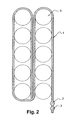
- Figure 2 illustrates the positioning of the flexible bag (1) relative to the enclosures (5).
- the speakers are cylindrical, of identical dimensions and arranged in two rows.
- the width of the flexible pouch is substantially equal to the height of the speakers.
- the length of the flexible pouch is wrapped around the first row of speakers and then around the second row of speakers.
- the length of a partition is chosen so that the sections located on either side of this partition are in contact with at least two enclosures. In a preferred embodiment, a section is in contact with all the speakers.
- partitions allow at least two sections having no common partition, are in contact with the same enclosure. These partitions can be evenly distributed over the height of the enclosure.
- partitions allows a passage of the heat transfer fluid in contact with several enclosures and several passages of the coolant in contact with the same enclosure.
- the presence of partitions has the advantage of reducing the temperature differences between the speakers located at both ends of the length of the flexible bag.
- the heat transfer fluid makes only one passage in contact with all the speakers.
- the speakers located at both The ends of the cooling device may have different temperatures due to the gradual heating of the heat transfer fluid caused by the contact of the fluid with each chamber.
- the coolant accumulates less heat during its journey between the two end chambers.
- the device according to the invention thus makes it possible to obtain less dispersed temperatures between the enclosures situated at the two ends of the cooling device.
- partitions has another advantage: it increases the mechanical rigidity of the flexible pouch relative to a flexible pouch having no partitions. The pocket is therefore easily placed in contact with the electrochemical elements.
- the partition is made by welding.
- the welding of steps b) and c) is a high-frequency weld.
- the flexible material used in the process according to the invention is a plastic material, chosen from the group comprising polyvinyl chloride or polyurethane.
- the device according to the invention is well suited to the regulation of the temperature of sealed storage cells such as the elements of a lithium-ion type battery. These generate a large amount of energy when they operate in charge or discharge under strong current, as is the case in vehicles with hybrid propulsion by engine and electric motor.
- a first thermal regulation device was manufactured as follows.
- a flexible pouch was formed by high frequency welding of edges of two polyurethane sheets.
- Three parallel partitions were manufactured by high-frequency welding of the surface of the two polyurethane sheets.
- the flexible pouch was arranged to surround the first row of the five elements and then the second row.
- the heat transfer fluid therefore performs a total of two round trips or four passages in contact with the same element.
- a second thermal control device not forming part of the invention was arranged in the same way around ten cylindrical accumulator elements arranged in two rows of five elements.
- This device comprises a rigid pocket without partitions.
- the elements undergo a cycling test comprising successive charges and discharges between about 3.45 V and 3.9 V at an ambient temperature of 25 ° C. These operating conditions cause the elements to overheat and the temperature control device is used to cool them.
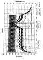
- the heat transfer fluid is circulated in the thermal control device using a pump. Its flow rate is set at 0.22L / min until about 1hr 20min after the start of the test. It is zero between 1hr 20min and 1hr 40min; then it is 0.26L / min until the end of the test ( Figure 3).
- the flow rate of the coolant in the thermal control device not forming part of the invention is set at 0.50L / min until about 1hr 20min after the start of the test, then it is set at 1.8L / min until 'at the end of the test ( Figure 4).
- the temperatures of the elements and connections cooled by the device according to the invention range from 36 to 40 ° C for a flow rate of 0.22 or 0.26 L / min while the temperatures of the elements and connections cooled by the device not forming part of the invention, go from 34 to 42 ° C for a flow rate of 0.5 L / min, the flow rate of 0.5 L / min being a priori more favorable to the good cooling of the elements.
- the present embodiment and the figures should be considered as illustrative and not restrictive, and the invention is not intended to be limited to battery cells.
- the invention can also be applied to control the temperature of any enclosure requiring temperature regulation, such as for example a chemical reactor enclosure.
Landscapes
- Engineering & Computer Science (AREA)
- Chemical & Material Sciences (AREA)
- Chemical Kinetics & Catalysis (AREA)
- Electrochemistry (AREA)
- General Chemical & Material Sciences (AREA)
- Manufacturing & Machinery (AREA)
- Physics & Mathematics (AREA)
- Thermal Sciences (AREA)
- Mechanical Engineering (AREA)
- General Engineering & Computer Science (AREA)
- Secondary Cells (AREA)
- Cooling Or The Like Of Electrical Apparatus (AREA)
Applications Claiming Priority (1)
| Application Number | Priority Date | Filing Date | Title |
|---|---|---|---|
| FR0507821A FR2888993A1 (fr) | 2005-07-22 | 2005-07-22 | Dispositif de regulation thermique |
Publications (2)
| Publication Number | Publication Date |
|---|---|
| EP1746672A2 true EP1746672A2 (de) | 2007-01-24 |
| EP1746672A3 EP1746672A3 (de) | 2008-02-06 |
Family
ID=36102623
Family Applications (1)
| Application Number | Title | Priority Date | Filing Date |
|---|---|---|---|
| EP20060291161 Withdrawn EP1746672A3 (de) | 2005-07-22 | 2006-07-18 | Vorrichtung zur thermischen regelung |
Country Status (3)
| Country | Link |
|---|---|
| US (1) | US20070037050A1 (de) |
| EP (1) | EP1746672A3 (de) |
| FR (1) | FR2888993A1 (de) |
Cited By (3)
| Publication number | Priority date | Publication date | Assignee | Title |
|---|---|---|---|---|
| WO2013120770A1 (en) * | 2012-02-18 | 2013-08-22 | Johnson Controls Advanced Power Solutions Gmbh | Assembly with a first and a second component and method for producing such an assembly |
| WO2016034356A3 (de) * | 2014-09-01 | 2016-04-28 | Robert Bosch Gmbh | Batteriebehälter enthaltend eine membranartige seite und verfahren zur dessen herstellung |
| WO2019129734A1 (fr) | 2017-12-27 | 2019-07-04 | Saft | Couvercle d'element electrochimique a conduction thermique renforcee |
Families Citing this family (16)
| Publication number | Priority date | Publication date | Assignee | Title |
|---|---|---|---|---|
| US8324868B2 (en) * | 2007-08-24 | 2012-12-04 | Valence Technology, Inc. | Power source with temperature sensing |
| CN102257652B (zh) | 2008-11-12 | 2014-04-02 | 江森自控帅福得先进能源动力系统有限责任公司 | 具有热交换器的电池系统 |
| WO2011088997A1 (de) * | 2010-01-20 | 2011-07-28 | Fraunhofer-Gesellschaft zur Förderung der angewandten Forschung e.V. | Temperierbare batteriezellenanordnung |
| DE102010021922A1 (de) * | 2010-05-28 | 2011-12-01 | Li-Tec Battery Gmbh | Kühlelement und Verfahren zum Herstellen desselben; elektrochemische Energiespeichervorrichtung mit Kühlelement |
| US9406917B2 (en) * | 2011-07-07 | 2016-08-02 | Federal Express Corporation | Battery cooling method and system |
| AT520018B1 (de) | 2017-06-13 | 2020-02-15 | Miba Emobility Gmbh | Akkumulator |
| AT520154B1 (de) | 2017-07-03 | 2019-04-15 | Miba Frictec Gmbh | Akkumulator |
| AT520409B1 (de) * | 2017-09-05 | 2020-02-15 | Miba Ag | Akkumulator |
| AT520410B1 (de) | 2017-09-14 | 2019-09-15 | Miba Ag | Akkumulator |
| AT520411B1 (de) | 2017-09-14 | 2019-09-15 | Miba Ag | Akkumulator |
| CN113809357A (zh) * | 2020-06-12 | 2021-12-17 | 亚太燃料电池科技股份有限公司 | 热能输送装置及其热传元件 |
| US20240159476A1 (en) * | 2020-06-12 | 2024-05-16 | Asia Pacific Fuel Cell Technologies, Ltd. | Heat transferring device and heat transferring component thereof |
| EP3922940A1 (de) * | 2020-06-12 | 2021-12-15 | Asia Pacific Fuel Cell Technologies, Ltd. | Wärmeübertragungsvorrichtung und wärmeübertragende komponente dafür |
| US11628745B2 (en) | 2021-02-05 | 2023-04-18 | Beta Air, Llc | Apparatus for a ground-based battery management for an electric aircraft |
| JP7142262B1 (ja) * | 2021-11-29 | 2022-09-27 | パナソニックIpマネジメント株式会社 | 通信制御装置および撮像装置 |
| CN216903119U (zh) * | 2022-03-30 | 2022-07-05 | 宁德时代新能源科技股份有限公司 | 电池热管理系统、电池及用电装置 |
Citations (5)
| Publication number | Priority date | Publication date | Assignee | Title |
|---|---|---|---|---|
| US5624003A (en) | 1992-12-10 | 1997-04-29 | Toyota Jidosha Kabushiki Kaisha | Battery temperature-raising device for electric vehicle |
| JPH1154157A (ja) | 1997-08-04 | 1999-02-26 | Toyota Motor Corp | 熱交換装置及びバッテリケース |
| US6228524B1 (en) | 1997-11-12 | 2001-05-08 | Varta Aktiengesellschaft | Storage battery with temperture-control device |
| WO2002007249A1 (de) | 2000-07-13 | 2002-01-24 | Daimlerchrysler Ag | Wärmetauscherstruktur für mehrere elektrochemische speicherzellen |
| EP1261065A2 (de) | 2001-05-23 | 2002-11-27 | Alcatel | Thermische Verwaltung mittels Abdeckung und Ummantlung von Batteriesystemmodulen |
Family Cites Families (6)
| Publication number | Priority date | Publication date | Assignee | Title |
|---|---|---|---|---|
| US4080953A (en) * | 1976-12-08 | 1978-03-28 | Minnesota Mining And Manufacturing Company | Electrochemical heating device |
| DE2751115A1 (de) * | 1977-11-16 | 1979-05-23 | Klaus Ing Grad Rennebeck | Formkoerper mit etwa wabenaehnlicher struktur fuer waermetauscher, wascher o.dgl. |
| US4793352A (en) * | 1986-02-07 | 1988-12-27 | Eichenlaub John E | Limited heat transfer device and method |
| FR2761203B1 (fr) * | 1997-03-24 | 1999-05-28 | Alsthom Cge Alcatel | Dispositif de gestion de la temperature d'une batterie de generateurs electrochimiques |
| FR2782399B3 (fr) * | 1998-08-13 | 2001-01-12 | Plastiques De France Ind | Dispositif et procede de regulation thermique, par exemple pour le refroidissement de batteries d'accumulateurs de vehicules electriques |
| US6479185B1 (en) * | 2000-04-04 | 2002-11-12 | Moltech Power Systems, Inc. | Extended life battery pack with active cooling |
-
2005
- 2005-07-22 FR FR0507821A patent/FR2888993A1/fr active Pending
-
2006
- 2006-07-18 EP EP20060291161 patent/EP1746672A3/de not_active Withdrawn
- 2006-07-19 US US11/458,528 patent/US20070037050A1/en not_active Abandoned
Patent Citations (5)
| Publication number | Priority date | Publication date | Assignee | Title |
|---|---|---|---|---|
| US5624003A (en) | 1992-12-10 | 1997-04-29 | Toyota Jidosha Kabushiki Kaisha | Battery temperature-raising device for electric vehicle |
| JPH1154157A (ja) | 1997-08-04 | 1999-02-26 | Toyota Motor Corp | 熱交換装置及びバッテリケース |
| US6228524B1 (en) | 1997-11-12 | 2001-05-08 | Varta Aktiengesellschaft | Storage battery with temperture-control device |
| WO2002007249A1 (de) | 2000-07-13 | 2002-01-24 | Daimlerchrysler Ag | Wärmetauscherstruktur für mehrere elektrochemische speicherzellen |
| EP1261065A2 (de) | 2001-05-23 | 2002-11-27 | Alcatel | Thermische Verwaltung mittels Abdeckung und Ummantlung von Batteriesystemmodulen |
Cited By (5)
| Publication number | Priority date | Publication date | Assignee | Title |
|---|---|---|---|---|
| WO2013120770A1 (en) * | 2012-02-18 | 2013-08-22 | Johnson Controls Advanced Power Solutions Gmbh | Assembly with a first and a second component and method for producing such an assembly |
| US9660235B2 (en) | 2012-02-18 | 2017-05-23 | Johnson Controls Advanced Power Solutions Gmbh | Assembly with a first and a second component and method for producing such an assembly |
| WO2016034356A3 (de) * | 2014-09-01 | 2016-04-28 | Robert Bosch Gmbh | Batteriebehälter enthaltend eine membranartige seite und verfahren zur dessen herstellung |
| US10714713B2 (en) | 2014-09-01 | 2020-07-14 | Robert Bosch Gmbh | Clamping device for battery cells as well as battery module, battery, battery system, vehicle and method for producing a battery module |
| WO2019129734A1 (fr) | 2017-12-27 | 2019-07-04 | Saft | Couvercle d'element electrochimique a conduction thermique renforcee |
Also Published As
| Publication number | Publication date |
|---|---|
| FR2888993A1 (fr) | 2007-01-26 |
| EP1746672A3 (de) | 2008-02-06 |
| US20070037050A1 (en) | 2007-02-15 |
Similar Documents
| Publication | Publication Date | Title |
|---|---|---|
| EP1746672A2 (de) | Vorrichtung zur thermischen regelung | |
| WO2020044002A1 (fr) | Structure de gestion thermique a canaux integres | |
| JP2020510965A (ja) | 電池セルの表面を冷却するための不均一流路を備えたクーリングジャケット及びそれを含むバッテリーモジュール | |
| EP3764423A1 (de) | Busbar für batteriepaket, der zur elektrischen verbindung mindestens eines akkus des pakets bestimmt ist sowie zur zirkulation einer wärmeübertragungsflüssigkeit in seinem innern für die optimale kühlung des akkus und des batteriepakets, insbesondere im falle von thermischem durchgehen | |
| FR3075475A1 (fr) | Systeme de suivi des gaz au sein d'un pack-batterie, accumulateur electrochimique metal-ion associe comprenant une traversee formant borne pour integrant un event de securite pour le systeme de suivi | |
| FR2789231A1 (fr) | Alimentation a accumulateurs ou condensateurs, notamment pour automobile electrique | |
| CN103053067A (zh) | 具有新型结构的电池组 | |
| FR3007895A1 (fr) | Bande de cellules electrochimiques pour realiser un module de batterie pour vehicule electrique ou hybride, et procede de realisation d'un tel module | |
| JP2009515312A (ja) | 電池パックの密封型熱交換システム | |
| KR102158364B1 (ko) | 배터리 모듈, 이러한 배터리 모듈을 포함하는 배터리 팩 및 이러한 배터리 팩을 포함하는 자동차 | |
| EP3046178B1 (de) | Batterie, die mit einer vorrichtung zur wärmeregulierung der elektrochemischen elemente ausgestattet ist, und entsprechendes herstellungsverfahren | |
| EP3499606A1 (de) | Mechanisches schnittstellenelement, das auch zur elektrischen isolierung zwischen zwei elektrochemischen metallionen-akkus dient, die auf ihrer längsachse in reihe geschaltet sind, und entsprechendes akku-modul | |
| FR3075477A1 (fr) | Traversee formant borne pour accumulateur electrochimique metal-ion, accumulateur associe | |
| EP2625740B1 (de) | Batteriefach für ein fahrzeug | |
| EP4595148A1 (de) | Vorrichtung zum beabstanden von batteriezellen eines fahrzeugbatteriepacks | |
| EP3925018A1 (de) | Batterieeinheit und kraftfahrzeug mit mindestens einer solchen einheit | |
| EP3840099A1 (de) | Elektrochemischer akku, insbesondere metall-ionen-akku, mit weicher verpackung, die eine oder mehrere kühlflüssigkeitsdurchlassöffnungen umfasst, entsprechendes modul und herstellungsverfahren | |
| KR101853907B1 (ko) | 배터리 모듈 및 이를 포함하는 배터리 팩 | |
| WO2022214571A1 (fr) | Plaque longitudinale pour dispositif de traitement thermique | |
| EP3840103A1 (de) | Elektrochemischer akku, insbesondere metall-ionen-akku, mit weicher verpackung, die kühlkanäle umfasst, entsprechendes modul und entsprechendes herstellungsverfahren | |
| WO2023117517A1 (fr) | Module pour batterie comprenant un fluide appliquant une pression sur une cellule | |
| FR3107613A1 (fr) | Module de batterie d’un vehicule | |
| FR3056829A1 (fr) | Dispositif de regulation thermique de batterie | |
| KR20130073106A (ko) | 냉각파이프가 장착된 배터리모듈 | |
| WO2021123559A1 (fr) | Dispositif d'échange thermique pour des composants électriques et/ou électroniques |
Legal Events
| Date | Code | Title | Description |
|---|---|---|---|
| PUAI | Public reference made under article 153(3) epc to a published international application that has entered the european phase |
Free format text: ORIGINAL CODE: 0009012 |
|
| AK | Designated contracting states |
Kind code of ref document: A2 Designated state(s): AT BE BG CH CY CZ DE DK EE ES FI FR GB GR HU IE IS IT LI LT LU LV MC NL PL PT RO SE SI SK TR |
|
| AX | Request for extension of the european patent |
Extension state: AL BA HR MK YU |
|
| PUAL | Search report despatched |
Free format text: ORIGINAL CODE: 0009013 |
|
| AK | Designated contracting states |
Kind code of ref document: A3 Designated state(s): AT BE BG CH CY CZ DE DK EE ES FI FR GB GR HU IE IS IT LI LT LU LV MC NL PL PT RO SE SI SK TR |
|
| AX | Request for extension of the european patent |
Extension state: AL BA HR MK YU |
|
| RIC1 | Information provided on ipc code assigned before grant |
Ipc: F28F 3/12 20060101ALI20080102BHEP Ipc: F28F 21/06 20060101ALI20080102BHEP Ipc: H01M 2/10 20060101ALI20080102BHEP Ipc: H01M 6/50 20060101ALI20080102BHEP Ipc: H01M 10/50 20060101AFI20080102BHEP |
|
| AKX | Designation fees paid | ||
| REG | Reference to a national code |
Ref country code: DE Ref legal event code: 8566 |
|
| STAA | Information on the status of an ep patent application or granted ep patent |
Free format text: STATUS: THE APPLICATION IS DEEMED TO BE WITHDRAWN |
|
| 18D | Application deemed to be withdrawn |
Effective date: 20080807 |