EP1262392A2 - Système d'isolation de vibrations d'une colonne de direction assistée - Google Patents
Système d'isolation de vibrations d'une colonne de direction assistée Download PDFInfo
- Publication number
- EP1262392A2 EP1262392A2 EP02076714A EP02076714A EP1262392A2 EP 1262392 A2 EP1262392 A2 EP 1262392A2 EP 02076714 A EP02076714 A EP 02076714A EP 02076714 A EP02076714 A EP 02076714A EP 1262392 A2 EP1262392 A2 EP 1262392A2
- Authority
- EP
- European Patent Office
- Prior art keywords
- sleeve
- bushing
- disposed
- column
- housing
- Prior art date
- Legal status (The legal status is an assumption and is not a legal conclusion. Google has not performed a legal analysis and makes no representation as to the accuracy of the status listed.)
- Granted
Links
Images

Classifications
-
- B—PERFORMING OPERATIONS; TRANSPORTING
- B62—LAND VEHICLES FOR TRAVELLING OTHERWISE THAN ON RAILS
- B62D—MOTOR VEHICLES; TRAILERS
- B62D5/00—Power-assisted or power-driven steering
- B62D5/04—Power-assisted or power-driven steering electrical, e.g. using an electric servo-motor connected to, or forming part of, the steering gear
- B62D5/0409—Electric motor acting on the steering column
-
- B—PERFORMING OPERATIONS; TRANSPORTING
- B62—LAND VEHICLES FOR TRAVELLING OTHERWISE THAN ON RAILS
- B62D—MOTOR VEHICLES; TRAILERS
- B62D7/00—Steering linkage; Stub axles or their mountings
- B62D7/22—Arrangements for reducing or eliminating reaction, e.g. vibration, from parts, e.g. wheels, of the steering system
- B62D7/224—Arrangements for reducing or eliminating reaction, e.g. vibration, from parts, e.g. wheels, of the steering system acting between the steering wheel and the steering gear, e.g. on the steering column
Definitions
- Certain motor vehicles contain column-type electric power steering systems.
- the electric power steering system provides torque assist to the steering shaft of a vehicle via an electric motor and a worm/worm gear reduction mechanism.
- the worm/worm gear reduction mechanism is interposed between the output shaft and the motor to obtain an appropriate steering speed as well as sufficient steering assistance in the course of transmission of the rotational force from the motor to the output shaft.
- a method and apparatus for reducing rattle and increasing road feel at a steerable wheel in a vehicle When road impact energy is transmitted through a transmission medium, which includes a column mounted electric power steering system, an audible noise may be generated throughout a steering system of a vehicle. Interrupting the transmission medium and absorbing the road impact energy through the steering system reduces the audible noise in the steering system and increases the road feel at the steerable wheel of the vehicle.
- a column assist isolation system includes a sleeve disposed at a housing of an electric power steering system, a first bushing disposed at a first end of the sleeve, and a second bushing disposed at a second end of the sleeve. Both the first bushing and the second bushing include compliant materials.
- a column assist isolation system can be mounted on any type of column mounted electric power steering (EPS) system.
- Column mounted EPS systems generally includes shafts, gears, and other components that connect the steerable wheels to the steerable device of a vehicle. These components, also known as a transmission medium, have certain material and engagement characteristics that allow vibration to cause audible noise and to be transmitted throughout the steering system and heard by the occupants of the vehicle.
- the column assist isolation system absorbs, reflects, and dissipates vibration at the transmission medium that occurs due to the road impact energy. Absorbing, reflecting, and dissipating vibration at the transmission medium reduces the noise throughout the transmission medium.
- the column assist isolation system enhances the steering feel at the steering device of a vehicle in which the system is installed.
- the functionality of the column assist isolation system is the same regardless of the type of column mounted EPS system. For this reason, the column assist isolation system can be applied by one of ordinary skill in the art to any column mounted EPS system.
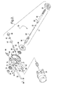
- Steering system 10 alters the direction of travel of a motor vehicle (not shown) in response to an input from an operator of the motor vehicle, a sensor disposed in the motor vehicle, or a combination thereof. Such a response ultimately changes the angle of the steerable wheels of the motor vehicle while the motor vehicle is traveling. By changing the angle of the steerable wheels while the motor vehicle is traveling, a change in the direction of travel can be effectuated.
- Steering system 10 comprises a steering device 14, which is accessible by an operator (not shown) of the motor vehicle and is disposed on a steering shaft 17.
- the rotational force of steering device 14 is transmitted to steering shaft 17, and is detected by a torque sensor 30 disposed thereon.
- Torque sensor 30 measures the torque exerted on steering shaft 17 in axial directions and transmits a signal 31 to a controller 32.
- Controller 32 then transmits an output signal 33 to a motor 34 to initiate the operation of motor 34.
- Motor 34 is in operable communication with a worm shaft 36 so that motor 34 drives worm shaft 36.
- Worm shaft 36 axially rotates, which causes worm 38 (shown on Figure 2) to rotate.
- Worm 38 meshes with worm gear 26, which rotates when worm 38 rotates.
- Worm gear 26 provides turning assistance to steering shaft 17.
- intermediate shaft 52 disposed in mechanical communication with a coupling joint 58 rotates a pinion gear (not shown) located under a gear housing 60.
- Coupling joint 58 may be a universal joint, as shown, or a torsional member.
- Rotation of the pinion gear (not shown) which is located in a housing 60, moves a rack 62, which moves tie rods 64 (only one shown).
- tie rods 64 move, they turn steering knuckles 66 (only one shown), which turn steerable wheels 12 (only one shown).
- Steering shaft 17 comprises an upper shaft 16, which is in operable communication with a lower shaft 18 through a torsion bar 20. Needle bearing 22 and pin 24 support torsion bar 20 and are located at the connection between torsion bar 20 and upper shaft 16. A worm gear 26 is in operable communication with lower shaft 18. A bearing 28 supports lower shaft 18 at worm gear 26.
- a worm 38 is connected to a worm shaft 36.
- Worm shaft 36 is supported by two bearings 40, 42.
- bearing 42 On one side of worm shaft 36, bearing 42 is pressed against worm 38 and axially retained by a nut 44 and a plug 46.
- bearing 40 On the opposite side of worm shaft 36, bearing 40 is pressed against worm 38 and axially supported by a retaining ring 48.
- motor 34 Upon operation of motor 34, worm shaft 36 is driven and worm 38 and worm gear 26 correspondingly rotate to provide turning assistance to lower shaft 18.
- Worm gear 26 may be contained in a housing 50.
- Lower shaft 18 extends through housing 50 and from a downside end 70 thereof to maintain operable communication with an intermediate shaft (not shown).
- a bearing 54 supports housing 50 at lower shaft 18 and is axially secured by a nut 56.
- a column assist isolation system 68 is mounted to downside end 70 of housing 50.
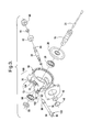
- Column assist isolation system 68 comprises a sleeve support 72, which may be either connected to housing 50 or molded as part of housing 50 that extends from downside end 70.
- Sleeve support 72 may be cylindrically shaped and comprises a first sleeve support 74 and a second sleeve support 76.
- Sleeve 78 is inserted through an opening 75 in first sleeve support 74 and inserted through an opening (not shown) in second sleeve support 76 so that a first end 80 of sleeve 78 is supported by first sleeve support 74 and a second end 82 of sleeve 78 is supported by second sleeve support 76.
- First end 80 of sleeve 78 is retained at first sleeve support 74 by a first bushing 84.
- First bushing 84 is pressed onto first end 80 of sleeve 78 so that an elongated end 88 of first bushing 84 is pressed between first sleeve support 74 and sleeve 78.
- Second end 82 of sleeve 78 is retained at second sleeve support 76 by a second bushing 86.
- Second bushing 86 is pressed onto second end 82 of sleeve 78 so that an elongated end 90 of second bushing 86 is pressed between second sleeve support 76 and sleeve 78.
- First bushing 84 and second bushing 86 are made of a material that has compliant properties.
- An example of such material is that the material could contain a certain amount of rubber or elastomer or be made completely from rubber or elastomer.
- First bushing 84 and second bushing 86 may also be formed from a wire mesh, or a steel wool material.
- spring washers would also be appropriate to provide the compliant properties.
- other materials may also be used so long as such materials have compliant properties.
- Sleeve 78 does not need to be any special material, however, a hard material is preferable. For instance, materials such as wood, plastic, or steel are examples of materials that could be used for sleeve 78.
- First bushing 84 is fixably attached to first end 80 of sleeve 78 and second bushing 86 is fixably attached to second end 82 of sleeve 78, which together form a bushing/sleeve unit 100.
- Downside end 70 of housing 50 comprises a sleeve support 72, as described above with reference to Figure 2, but which also comprises an open slot 102 located at first sleeve support 74 and an open slot 104 located at second sleeve support 76.
- Open slots 102, 104 are sized so as to allow bushing/sleeve unit 100 to be pressed into and retained at first sleeve support 74 and second sleeve support 76.
- the placement of the sleeve and the bushings at the downside end of the housing effectively reduces the rattle experienced by the steering system.
- Such a reduction in rattle is generally a function of the road impact energy being absorbed by the steering system
- the column assist isolation system also adds torsional compliance to the EPS assist mechanism.
- the type of material employed for the bushings allow the bushings to compress slightly when the steering system undergoes torsional stress.
- the additional torsional compliance at the EPS assist mechanism allows the electric power steering assist mechanism to move slightly and allows the road impact energy to be felt by the driver through the steering shaft, thereby increasing the road feel at the steering device.
Landscapes
- Engineering & Computer Science (AREA)
- Chemical & Material Sciences (AREA)
- Combustion & Propulsion (AREA)
- Transportation (AREA)
- Mechanical Engineering (AREA)
- Power Steering Mechanism (AREA)
- Steering Controls (AREA)
- Vibration Dampers (AREA)
Applications Claiming Priority (2)
| Application Number | Priority Date | Filing Date | Title |
|---|---|---|---|
| US09/867,298 US6550568B2 (en) | 2001-05-29 | 2001-05-29 | Column assist isolation system |
| US867298 | 2001-05-29 |
Publications (3)
| Publication Number | Publication Date |
|---|---|
| EP1262392A2 true EP1262392A2 (fr) | 2002-12-04 |
| EP1262392A3 EP1262392A3 (fr) | 2004-03-10 |
| EP1262392B1 EP1262392B1 (fr) | 2007-11-21 |
Family
ID=25349511
Family Applications (1)
| Application Number | Title | Priority Date | Filing Date |
|---|---|---|---|
| EP02076714A Expired - Lifetime EP1262392B1 (fr) | 2001-05-29 | 2002-05-01 | Système d'isolation de vibrations d'une colonne de direction assistée |
Country Status (4)
| Country | Link |
|---|---|
| US (1) | US6550568B2 (fr) |
| EP (1) | EP1262392B1 (fr) |
| JP (1) | JP2003040124A (fr) |
| DE (1) | DE60223622T2 (fr) |
Cited By (4)
| Publication number | Priority date | Publication date | Assignee | Title |
|---|---|---|---|---|
| FR2861357A1 (fr) * | 2003-10-28 | 2005-04-29 | Tokai Rubber Ind Ltd | Systeme de commande de vibrations pour systeme de direction a inclinaison electrique |
| WO2017102320A1 (fr) * | 2015-12-18 | 2017-06-22 | Robert Bosch Automotive Steering Gmbh | Procédé de détection d'un ou de plusieurs bruits suspects pendant le fonctionnement d'un véhicule automobile |
| US10807633B2 (en) | 2017-05-12 | 2020-10-20 | Ka Group Ag | Electric power steering assembly and system with anti-rotation coupler |
| US11511786B2 (en) * | 2019-09-04 | 2022-11-29 | Steering Solutions Ip Holding Corporation | Rattle noise reducing electric power steering column assembly and method |
Families Citing this family (9)
| Publication number | Priority date | Publication date | Assignee | Title |
|---|---|---|---|---|
| US6681883B2 (en) * | 2002-03-12 | 2004-01-27 | Ford Global Technologies, Llc | Method and apparatus for suppressing vibration in vehicle a steering system |
| US7055647B2 (en) * | 2004-07-02 | 2006-06-06 | Nacam France Sa | Electrically-assisted steering mechanism for vehicles |
| US20080093156A1 (en) * | 2006-10-24 | 2008-04-24 | Peringat Jagadish K | Modular steering gear housing |
| JP2008184083A (ja) * | 2007-01-31 | 2008-08-14 | Fuji Kiko Co Ltd | 舵角比可変ステアリング装置 |
| US7742899B2 (en) * | 2008-02-12 | 2010-06-22 | Gm Global Technology Operations, Inc. | Test procedure for determining steering rack rattle |
| US7866435B2 (en) * | 2008-04-21 | 2011-01-11 | Nexteer (Beijing) Technology Co., Ltd. | Electric power steering rotation isolator |
| US11001294B2 (en) | 2017-08-23 | 2021-05-11 | Steering Solutions Ip Holding Corporation | Steering column power assist assembly housing |
| US10718686B2 (en) * | 2018-10-29 | 2020-07-21 | GM Global Technology Operations LLC | Test procedure for determining steering intermediate shaft rattle |
| US11506259B2 (en) * | 2019-10-11 | 2022-11-22 | Steering Solutions Ip Holding Corporation | Cantilevered worm gear assembly with limiter bushing |
Family Cites Families (16)
| Publication number | Priority date | Publication date | Assignee | Title |
|---|---|---|---|---|
| JPS5929147Y2 (ja) * | 1979-02-24 | 1984-08-22 | トヨタ自動車株式会社 | 弾性軸継手 |
| JPS6133367A (ja) * | 1984-07-25 | 1986-02-17 | Aisin Seiki Co Ltd | 電動パワ−ステアリングの動力伝達装置 |
| JPS6192959A (ja) * | 1984-10-11 | 1986-05-10 | Honda Motor Co Ltd | 電動式パワ−ステアリング装置 |
| JPH0275375U (fr) * | 1988-11-30 | 1990-06-08 | ||
| US5259818A (en) * | 1989-04-14 | 1993-11-09 | Fuji Kiko Company, Limited | Stroke absorbing type intermediate shaft for vehicular steering column and method for assembling the same |
| US5704254A (en) * | 1995-02-13 | 1998-01-06 | Chrysler Corporation | Steering column isolator pads |
| JP3604460B2 (ja) * | 1995-06-14 | 2004-12-22 | 光洋精工株式会社 | 電動パワーステアリング装置 |
| DE19531201A1 (de) * | 1995-08-24 | 1997-02-27 | Sgf Gmbh & Co Kg | Schwingungsdämpfendes torsionselastisches Wellengelenk, insbesondere für den Antriebsstrang von Kraftfahrzeugen |
| KR0139454B1 (ko) * | 1995-10-18 | 1998-07-01 | 전성원 | 자동차의 조향축 마운트 구조 |
| GB2327652B (en) * | 1997-05-29 | 2001-04-18 | Nsk Ltd | Electric power assisted steering apparatus |
| US5878832A (en) * | 1997-08-13 | 1999-03-09 | General Motors Corporation | Steering apparatus for motor vehicle |
| US5960673A (en) * | 1998-04-02 | 1999-10-05 | Chrysler Corporation | Isolator pad for a steering column |
| JP2000159128A (ja) * | 1998-11-26 | 2000-06-13 | Nsk Ltd | 電動式パワーステアリング装置 |
| JP4275833B2 (ja) * | 2000-01-13 | 2009-06-10 | 株式会社ショーワ | 電動パワーステアリング装置 |
| US6378647B1 (en) * | 2000-09-26 | 2002-04-30 | Delphi Technologies, Inc. | Electric power steering assist mechanism with isolated output shaft |
| US6389924B1 (en) * | 2000-12-05 | 2002-05-21 | Delphi Technologies, Inc. | Steering column for motor vehicle |
-
2001
- 2001-05-29 US US09/867,298 patent/US6550568B2/en not_active Expired - Fee Related
-
2002
- 2002-05-01 EP EP02076714A patent/EP1262392B1/fr not_active Expired - Lifetime
- 2002-05-01 DE DE60223622T patent/DE60223622T2/de not_active Expired - Lifetime
- 2002-05-29 JP JP2002155969A patent/JP2003040124A/ja active Pending
Non-Patent Citations (1)
| Title |
|---|
| None |
Cited By (5)
| Publication number | Priority date | Publication date | Assignee | Title |
|---|---|---|---|---|
| FR2861357A1 (fr) * | 2003-10-28 | 2005-04-29 | Tokai Rubber Ind Ltd | Systeme de commande de vibrations pour systeme de direction a inclinaison electrique |
| US7226082B2 (en) | 2003-10-28 | 2007-06-05 | Tokai Rubber Industries, Ltd. | Vibration control system for electric tilt steering |
| WO2017102320A1 (fr) * | 2015-12-18 | 2017-06-22 | Robert Bosch Automotive Steering Gmbh | Procédé de détection d'un ou de plusieurs bruits suspects pendant le fonctionnement d'un véhicule automobile |
| US10807633B2 (en) | 2017-05-12 | 2020-10-20 | Ka Group Ag | Electric power steering assembly and system with anti-rotation coupler |
| US11511786B2 (en) * | 2019-09-04 | 2022-11-29 | Steering Solutions Ip Holding Corporation | Rattle noise reducing electric power steering column assembly and method |
Also Published As
| Publication number | Publication date |
|---|---|
| DE60223622D1 (de) | 2008-01-03 |
| US20020179361A1 (en) | 2002-12-05 |
| DE60223622T2 (de) | 2008-10-23 |
| EP1262392B1 (fr) | 2007-11-21 |
| EP1262392A3 (fr) | 2004-03-10 |
| US6550568B2 (en) | 2003-04-22 |
| JP2003040124A (ja) | 2003-02-13 |
Similar Documents
| Publication | Publication Date | Title |
|---|---|---|
| US6550568B2 (en) | Column assist isolation system | |
| KR20110009274A (ko) | 전동식 동력 보조 조향장치의 감속기 | |
| KR20130048837A (ko) | 랙구동형 조향장치 및 이를 구비한 랙구동형 동력 보조 조향장치 | |
| JPH01106776A (ja) | 動力舵取装置 | |
| CN1332842C (zh) | 电动助力转向装置 | |
| JP3763347B2 (ja) | 電動式舵取装置 | |
| JP3888819B2 (ja) | 電動パワーステアリング装置 | |
| US5937704A (en) | Cable-type steering device | |
| KR101085336B1 (ko) | 세레이션이 형성된 댐핑 커플러를 구비한 자동차의 전기식동력 보조 조향장치 | |
| JP3104165B2 (ja) | 車両用ステアリング装置 | |
| KR101261094B1 (ko) | 전동식 동력 보조 조향장치의 감속기 | |
| KR20130074074A (ko) | 자동차의 전기식 동력 보조 조향장치 | |
| KR101251241B1 (ko) | 전동식 동력 보조 조향장치의 감속기 | |
| KR20080007811A (ko) | 차량용 전동 스티어링 장치의 기어 치합 상태 유지장치 | |
| JP4817899B2 (ja) | 電動式パワーステアリング機構を備える車両用ステアリング装置およびその組立方法 | |
| JP4567502B2 (ja) | 電動パワーステアリング装置 | |
| JP4014309B2 (ja) | パワーステアリング装置におけるラックシャフトの軸受構造 | |
| JP6256778B2 (ja) | 電動パワーステアリング装置 | |
| JP3951110B2 (ja) | 電動パワーステアリング装置の防振構造 | |
| KR100349396B1 (ko) | 와이어 스티어링장치용 조향 보조장치 | |
| KR930004011Y1 (ko) | 파워스티어링 장치 | |
| KR20060101622A (ko) | 전동식 파워 스티어링 장치의 감속기 유격보상구조 | |
| JP2005247080A (ja) | 電動パワーステアリング装置 | |
| JPH10271901A (ja) | 耕耘機の伝動機構 | |
| JP2002331942A (ja) | 操舵補助装置の取付部材 |
Legal Events
| Date | Code | Title | Description |
|---|---|---|---|
| PUAI | Public reference made under article 153(3) epc to a published international application that has entered the european phase |
Free format text: ORIGINAL CODE: 0009012 |
|
| AK | Designated contracting states |
Kind code of ref document: A2 Designated state(s): AT BE CH CY DE DK ES FI FR GB GR IE IT LI LU MC NL PT SE TR |
|
| AX | Request for extension of the european patent |
Free format text: AL;LT;LV;MK;RO;SI |
|
| PUAL | Search report despatched |
Free format text: ORIGINAL CODE: 0009013 |
|
| AK | Designated contracting states |
Kind code of ref document: A3 Designated state(s): AT BE CH CY DE DK ES FI FR GB GR IE IT LI LU MC NL PT SE TR |
|
| AX | Request for extension of the european patent |
Extension state: AL LT LV MK RO SI |
|
| 17P | Request for examination filed |
Effective date: 20040910 |
|
| AKX | Designation fees paid |
Designated state(s): DE FR GB IT |
|
| 17Q | First examination report despatched |
Effective date: 20050913 |
|
| GRAP | Despatch of communication of intention to grant a patent |
Free format text: ORIGINAL CODE: EPIDOSNIGR1 |
|
| GRAS | Grant fee paid |
Free format text: ORIGINAL CODE: EPIDOSNIGR3 |
|
| GRAA | (expected) grant |
Free format text: ORIGINAL CODE: 0009210 |
|
| AK | Designated contracting states |
Kind code of ref document: B1 Designated state(s): DE FR GB IT |
|
| REG | Reference to a national code |
Ref country code: GB Ref legal event code: FG4D |
|
| REF | Corresponds to: |
Ref document number: 60223622 Country of ref document: DE Date of ref document: 20080103 Kind code of ref document: P |
|
| ET | Fr: translation filed | ||
| PLBE | No opposition filed within time limit |
Free format text: ORIGINAL CODE: 0009261 |
|
| STAA | Information on the status of an ep patent application or granted ep patent |
Free format text: STATUS: NO OPPOSITION FILED WITHIN TIME LIMIT |
|
| 26N | No opposition filed |
Effective date: 20080822 |
|
| PGFP | Annual fee paid to national office [announced via postgrant information from national office to epo] |
Ref country code: GB Payment date: 20080507 Year of fee payment: 7 |
|
| GBPC | Gb: european patent ceased through non-payment of renewal fee |
Effective date: 20090501 |
|
| PG25 | Lapsed in a contracting state [announced via postgrant information from national office to epo] |
Ref country code: GB Free format text: LAPSE BECAUSE OF NON-PAYMENT OF DUE FEES Effective date: 20090501 |
|
| REG | Reference to a national code |
Ref country code: FR Ref legal event code: TP |
|
| PG25 | Lapsed in a contracting state [announced via postgrant information from national office to epo] |
Ref country code: IT Free format text: LAPSE BECAUSE OF NON-PAYMENT OF DUE FEES Effective date: 20080531 |
|
| REG | Reference to a national code |
Ref country code: DE Ref legal event code: R081 Ref document number: 60223622 Country of ref document: DE Owner name: GM GLOBAL TECHNOLOGY OPERATIONS LLC (N. D. GES, US Free format text: FORMER OWNER: DELPHI TECHNOLOGIES, INC., TROY, US Effective date: 20110412 Ref country code: DE Ref legal event code: R081 Ref document number: 60223622 Country of ref document: DE Owner name: STEERING SOLUTIONS IP HOLDING CORP., US Free format text: FORMER OWNER: DELPHI TECHNOLOGIES, INC., TROY, US Effective date: 20110412 Ref country code: DE Ref legal event code: R081 Ref document number: 60223622 Country of ref document: DE Owner name: STEERING SOLUTIONS IP HOLDING CORP., SAGINAW, US Free format text: FORMER OWNER: DELPHI TECHNOLOGIES, INC., TROY, MICH., US Effective date: 20110412 Ref country code: DE Ref legal event code: R081 Ref document number: 60223622 Country of ref document: DE Owner name: GM GLOBAL TECHNOLOGY OPERATIONS LLC (N. D. GES, US Free format text: FORMER OWNER: DELPHI TECHNOLOGIES, INC., TROY, MICH., US Effective date: 20110412 |
|
| PGFP | Annual fee paid to national office [announced via postgrant information from national office to epo] |
Ref country code: DE Payment date: 20120529 Year of fee payment: 11 |
|
| PGFP | Annual fee paid to national office [announced via postgrant information from national office to epo] |
Ref country code: FR Payment date: 20120607 Year of fee payment: 11 |
|
| REG | Reference to a national code |
Ref country code: DE Ref legal event code: R082 Ref document number: 60223622 Country of ref document: DE Representative=s name: MANITZ, FINSTERWALD & PARTNER GBR, DE |
|
| REG | Reference to a national code |
Ref country code: DE Ref legal event code: R082 Ref document number: 60223622 Country of ref document: DE Representative=s name: MANITZ, FINSTERWALD & PARTNER GBR, DE Effective date: 20121019 Ref country code: DE Ref legal event code: R081 Ref document number: 60223622 Country of ref document: DE Owner name: GM GLOBAL TECHNOLOGY OPERATIONS LLC (N. D. GES, US Free format text: FORMER OWNER: GM GLOBAL TECHNOLOGY OPERATIONS, INC., DETROIT, US Effective date: 20121019 Ref country code: DE Ref legal event code: R081 Ref document number: 60223622 Country of ref document: DE Owner name: STEERING SOLUTIONS IP HOLDING CORP., US Free format text: FORMER OWNER: GM GLOBAL TECHNOLOGY OPERATIONS, INC., DETROIT, US Effective date: 20121019 Ref country code: DE Ref legal event code: R081 Ref document number: 60223622 Country of ref document: DE Owner name: GM GLOBAL TECHNOLOGY OPERATIONS LLC (N. D. GES, US Free format text: FORMER OWNER: GM GLOBAL TECHNOLOGY OPERATIONS, INC., DETROIT, MICH., US Effective date: 20121019 Ref country code: DE Ref legal event code: R081 Ref document number: 60223622 Country of ref document: DE Owner name: STEERING SOLUTIONS IP HOLDING CORP., SAGINAW, US Free format text: FORMER OWNER: GM GLOBAL TECHNOLOGY OPERATIONS, INC., DETROIT, MICH., US Effective date: 20121019 |
|
| REG | Reference to a national code |
Ref country code: DE Ref legal event code: R082 Ref document number: 60223622 Country of ref document: DE Representative=s name: MANITZ, FINSTERWALD & PARTNER GBR, DE |
|
| REG | Reference to a national code |
Ref country code: DE Ref legal event code: R081 Ref document number: 60223622 Country of ref document: DE Owner name: GM GLOBAL TECHNOLOGY OPERATIONS LLC (N. D. GES, US Free format text: FORMER OWNER: GM GLOBAL TECHNOLOGY OPERATIONS LLC (N. D. GES. D. STAATES DELAWARE), DETROIT, US Effective date: 20130313 Ref country code: DE Ref legal event code: R081 Ref document number: 60223622 Country of ref document: DE Owner name: STEERING SOLUTIONS IP HOLDING CORP., US Free format text: FORMER OWNER: GM GLOBAL TECHNOLOGY OPERATIONS LLC (N. D. GES. D. STAATES DELAWARE), DETROIT, US Effective date: 20130313 Ref country code: DE Ref legal event code: R082 Ref document number: 60223622 Country of ref document: DE Representative=s name: MANITZ, FINSTERWALD & PARTNER GBR, DE Effective date: 20130313 Ref country code: DE Ref legal event code: R081 Ref document number: 60223622 Country of ref document: DE Owner name: GM GLOBAL TECHNOLOGY OPERATIONS LLC (N. D. GES, US Free format text: FORMER OWNER: GM GLOBAL TECHNOLOGY OPERATIONS LLC (N. D. GES. D. STAATES DELAWARE), DETROIT, MICH., US Effective date: 20130313 Ref country code: DE Ref legal event code: R081 Ref document number: 60223622 Country of ref document: DE Owner name: STEERING SOLUTIONS IP HOLDING CORP., SAGINAW, US Free format text: FORMER OWNER: GM GLOBAL TECHNOLOGY OPERATIONS LLC (N. D. GES. D. STAATES DELAWARE), DETROIT, MICH., US Effective date: 20130313 |
|
| PG25 | Lapsed in a contracting state [announced via postgrant information from national office to epo] |
Ref country code: DE Free format text: LAPSE BECAUSE OF NON-PAYMENT OF DUE FEES Effective date: 20131203 |
|
| REG | Reference to a national code |
Ref country code: FR Ref legal event code: ST Effective date: 20140131 |
|
| REG | Reference to a national code |
Ref country code: DE Ref legal event code: R119 Ref document number: 60223622 Country of ref document: DE Effective date: 20131203 |
|
| PG25 | Lapsed in a contracting state [announced via postgrant information from national office to epo] |
Ref country code: FR Free format text: LAPSE BECAUSE OF NON-PAYMENT OF DUE FEES Effective date: 20130531 |
|
| REG | Reference to a national code |
Ref country code: FR Ref legal event code: TQ Owner name: STEERING SOLUTIONS IP HOLDING CORPORATION, US Effective date: 20150723 Ref country code: FR Ref legal event code: CD Owner name: STEERING SOLUTIONS IP HOLDING CORPORATION, US Effective date: 20150723 Ref country code: FR Ref legal event code: CD Owner name: GM GLOBAL TECHNOLOGY OPERATIONS LLC, US Effective date: 20150723 Ref country code: FR Ref legal event code: TQ Owner name: GM GLOBAL TECHNOLOGY OPERATIONS LLC, US Effective date: 20150723 |