EP1262626A2 - Dispositif comprenant un volet roulant, des rails de guidage et une serrure - Google Patents
Dispositif comprenant un volet roulant, des rails de guidage et une serrure Download PDFInfo
- Publication number
- EP1262626A2 EP1262626A2 EP02005556A EP02005556A EP1262626A2 EP 1262626 A2 EP1262626 A2 EP 1262626A2 EP 02005556 A EP02005556 A EP 02005556A EP 02005556 A EP02005556 A EP 02005556A EP 1262626 A2 EP1262626 A2 EP 1262626A2
- Authority
- EP
- European Patent Office
- Prior art keywords
- locking
- guide rail
- cylinder housing
- recess
- arrangement according
- Prior art date
- Legal status (The legal status is an assumption and is not a legal conclusion. Google has not performed a legal analysis and makes no representation as to the accuracy of the status listed.)
- Withdrawn
Links
- 241000446313 Lamella Species 0.000 claims description 17
- 230000000903 blocking effect Effects 0.000 description 4
- 206010053648 Vascular occlusion Diseases 0.000 description 3
- 238000004519 manufacturing process Methods 0.000 description 2
- 230000015572 biosynthetic process Effects 0.000 description 1
- 238000010276 construction Methods 0.000 description 1
- 238000006073 displacement reaction Methods 0.000 description 1
- 230000000694 effects Effects 0.000 description 1
- 210000003746 feather Anatomy 0.000 description 1
- 230000003287 optical effect Effects 0.000 description 1
- 239000002689 soil Substances 0.000 description 1
Images




Classifications
-
- E—FIXED CONSTRUCTIONS
- E06—DOORS, WINDOWS, SHUTTERS, OR ROLLER BLINDS IN GENERAL; LADDERS
- E06B—FIXED OR MOVABLE CLOSURES FOR OPENINGS IN BUILDINGS, VEHICLES, FENCES OR LIKE ENCLOSURES IN GENERAL, e.g. DOORS, WINDOWS, BLINDS, GATES
- E06B9/00—Screening or protective devices for wall or similar openings, with or without operating or securing mechanisms; Closures of similar construction
- E06B9/02—Shutters, movable grilles, or other safety closing devices, e.g. against burglary
- E06B9/08—Roll-type closures
- E06B9/11—Roller shutters
- E06B9/115—Roller shutters specially adapted for furniture
-
- E—FIXED CONSTRUCTIONS
- E06—DOORS, WINDOWS, SHUTTERS, OR ROLLER BLINDS IN GENERAL; LADDERS
- E06B—FIXED OR MOVABLE CLOSURES FOR OPENINGS IN BUILDINGS, VEHICLES, FENCES OR LIKE ENCLOSURES IN GENERAL, e.g. DOORS, WINDOWS, BLINDS, GATES
- E06B9/00—Screening or protective devices for wall or similar openings, with or without operating or securing mechanisms; Closures of similar construction
- E06B9/56—Operating, guiding or securing devices or arrangements for roll-type closures; Spring drums; Tape drums; Counterweighting arrangements therefor
- E06B9/80—Safety measures against dropping or unauthorised opening; Braking or immobilising devices; Devices for limiting unrolling
- E06B2009/801—Locking arrangements
- E06B2009/805—Locking arrangements located on or in the guides
Definitions
- the invention relates to an arrangement with a roller shutter individual slats attached to each other by positive locking with lateral first and second ends of which one or several have or form a bolt recess together, a first guide rail and a second guide rail, each one of the lateral ends of the slats in one Take up the guide groove and the slats in one plane movably guide, a closure that the first guide rail is assigned and the one cylinder core, the indirect or is directly connected to a swivel bolt, and a cylinder housing in which the cylinder core between one Open position and a closed position pivotally added is.
- the roller shutter is secured at one end only, so that by applying force to the end remote from the lock cylinder the slats in the area of the second guide rail of the roller shutters can be opened easily. Furthermore, is not without activity the shutter to see if the shutter is in the secured position or not.
- the invention has for its object an arrangement with to propose a roller shutter, guide rails and a lock, in which the roller shutter is better against inadmissible opening is protected and also visually for the user can be seen whether the closure is in the closed position located or not.
- the cylinder housing is adjustable perpendicular to the plane between a position engaging in the first guide groove of the first guide rail, in which it engages in the locking recess, and a position extended from this out of engagement with the latter
- the closure further includes a receiving element, in which the cylinder housing is accommodated so as to be adjustable perpendicular to the plane, and which is held in a stationary manner with respect to the associated first guide rail, and spring means which act on the cylinder housing towards the extended position, and a latch retaining element, which is stationary with the first guide rail the guide groove of which the cylinder housing can be brought into engagement, is arranged and which has a locking slot to which the pivot bolt can be brought into engagement when the cylinder housing engages in the position of the guide groove by actuating the cylinder core, so that the cylinder housing is held in this position ,
- the in the closed position of the roller shutter adjacent to the cylinder housing i.e. opposite slat the latch recess at its first end for engagement of the cylinder housing.
- the Slat having bolt recess a locking bar is assigned, which passes through this lamella from the first recess of the first guide rail to the second Guide rail is guided out.
- a Actuating section provided on the locking bar. This has a locking section towards the second guide rail on.
- the cylinder housing has an adjustment section for Actuation of the actuating section, via which Locking bar engages with its locking section Locking element in the area of the second guide rail is movable.
- the locking element for example through a hole in the second Guide rail shown, in which the locking section entry.
- a spring can be assigned to the locking bar, through which they are disengaged from the locking element is acted upon.
- the bolt recess can also be formed that the slat is shortened. But it can also through the immediate formation of a bolt recess in be represented at its first end.
- the locking bar in the recess having slat it is possible to place the locking bar in the recess having slat to be pivoted.
- the locking section in a locking recess the locking element is pivotable and towards the actuating section against the locking element is supported. This can also be the assembly of a there is no need for a fixed intermediate floor for tall furniture.
- the closing position of the roller shutter adjacent or opposite Arrange slat so that it is adjacent to it Slats is slidably guided.
- That the second end of the slat towards the second Guide rail in engagement with a recess of a locking element or the second guide rail adjustable is.
- the sliding slat is the cylinder housing with one Adjustment section provided, which is in the form of an inclined Floor space is designed.
- one Adjustment section provided, which is in the form of an inclined Floor space is designed.
- Slidable or swiveling locking bar can additionally there may also be a blocking surface perpendicular to the plane, in which the slats of the roller shutter are located.
- the footprint is at an angle to this level.
- the bolt recess becomes that of the slidable slat adjacent slats limited.
- the cylinder housing be designed so that there is the space between the slidable slats spaced slats formed free space fills.
- roller shutters Adjusted by means of which the slats in the guide rails in position when the roller shutter is closed to the cylinder housing or the locking element and the locking hole can be aligned.
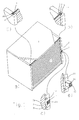
- the body 1 is, for example, office furniture shown, which can be closed by the roller shutter 2.
- the Roller shutter 2 consists of individual slats, of which only the important with position signs regarding the closing function, namely the position symbols 3, 3a and 3b are.
- the slats of the roller shutter 2 are in plane E with their first end 4 and second end 5 by a first guide rail 6 and a second guide rail 7 or through the first guide groove 9 and the second guide groove 10 out.
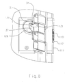
- the roller shutter is 2 closed by a closure 8. This works as follows described in connection with Figures 2 to 9 in more detail with one opposite in the closed position of the roller shutter 2 Slat or its immediately adjacent Slats to close together.
- the closure 8 comprises a fixed in the side wall of the body 1, which is the first guide rail 6, assigned receiving element 11.
- Das Receiving element 11 guides a cylinder housing 12, which is in cross section is rectangular, between one in the receiving element 11 inserted and one extended from this Position as shown by the two representations in figure ld) and 1e) recognizable, movable.
- Figure 1d Figure 1d
- Position that represents the unlocked position is that Cylinder housing 12 out of engagement with first guide groove 9.
- the roller shutter 2 can be in plane E along the two guide rails 6, 7 are moved upward, for example to release the area behind the body 1.
- the Securing the cylinder housing 12 in the in the receiving element 11 retracted position by means of a Cylinder key actuatable cylinder core 13, as follows is described. The design described above applies to all variants of the design of the closure.
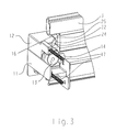
- a first embodiment of the closure is as follows described with reference to Figures 2 to 4.
- the springs 17 are supported on the cylinder housing 12 and on the end plate of the receiving element 11 onwards.
- the cylinder housing 12 is perpendicular to the plane E of the Slats 3 adjustable in the direction of the axis 15. It intervenes the retracted position, as shown in Figure 3 is in the bolt recess 16 and locks the Roller shutters 2 against adjustment in the guide rails 6, 7 in the open position.
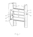
- a lock in the area the second guide rail 7 is provided. For this is in the the locking recess 16 having lamella 3 a locking bar 21 added by the slat 3 to the second Guide rail 7 is guided.
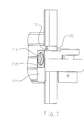
- the actuating section 22 of the locking bar 21 In the area of the transom recess 16 is the actuating section 22 of the locking bar 21. This is by the control section 24 in the form of an oblique Footprint acted upon so that when pressed of the cylinder housing 12 into the receiving element 11 Locking rod 21 is adjusted so that it is in the area of second guide rail 7, as shown in Figure 4 with her Latch section 23 in a locking hole in the second guide rail 7 occurs as a locking element 26. In this position the footprint has the control section 24 forms, the actuating section 22 passes, so that this is against one parallel to axis 15 and thus perpendicular to the plane E blocking portion 25 in shape supports a restricted area.
- a latch holding element in the area of the first guide rail 6 19, the component of the receiving element 11 and has a locking slot 20, in which the Swivel lock 14 with the cylinder housing 12 retracted and actuated Cylinder core 13 enters. This will make the cylinder housing 12 held in the retracted position.
- FIGS. 5 to 8 A second exemplary embodiment is based on FIGS. 5 to 8 explained in more detail.
- the locking bar 121 according to FIGS. 5 to 8 is a locking bar pivoted in the associated lamella 103, those in the area towards the cylinder housing 112, i.e.
- the one in the area of the second guide rail 107 arranged and also cranked latch portion 123 of Locking bar 121 is provided with a groove that has an inclined surface with which it engages with a projection 31 a locking element 126 with a corresponding one Inclined surface can be brought.
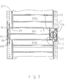
- FIG. 9 shows a further exemplary embodiment, in which the immediately adjacent to the cylinder housing 212 Slat 203 through the immediately adjacent slats 203a and 203b is slidably guided.
- the slats 203, 203a, 203b are fixed to each other and to each other by two pivoted slat elements formed.
- the first End 204 of the slidable slat 203 is through the adjusting section 224 applied to the cylinder housing 12 when this is inserted into the receiving element 211. This will the slat 203 in the direction of arrow X in the direction of the second Guide rail 207 displaces and engages with its second end 205 in a recess 29 of the second guide rail 207 on.
- the two slats spaced by the slat 203 203a, 203b form in the region of the first guide recess first guide rail 206 with the displaced slat 203 the latch recess 216 formed by the cylinder housing 212 is occupied so that the roller shutters 2 are not moved can. Due to the engagement of the lamella 203 in the recess 29 is also a lock in the area of the second guide rail 207 given. If the cylinder core 203 by means of a Cylinder key is moved to the open position, moves the spring-loaded cylinder housing 212 out of the receiving element 211 by a part so that it no longer in the engages first guide groove of the first guide rail 206.
- the second end 205 of the slat 203 becomes disengaged Recess 29 moves and is therefore only in Area of the second guide groove of the second guide rail 207, so that the slats of the roller shutter in the two guide rails 206, 207 can be moved into the open position.
- the locking plate 28 is towards the second End 205 of lamella 203 is convex, so that the lamella 203 are pushed completely out of the recess 29 can.
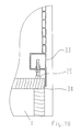
- adjusting means 35 for aligning the slats intended. This is to ensure an exact alignment of the Slat having the bolt recess or the one forming it Slats to the cylinder housing and the locking element allows become.
- the adjusting means 35 are in the form of adjusting screws provided that more or less deep in a final profile 33 of the roller shutter can be screwed in and closed state of the roller shutter 2 against a floor profile 34 Support the body 1 so that the slats in this position are aligned.
- the adjusting means 35 can be in the form of a Set screw arranged within two U-profiles 35, 37 his.
- the U-profiles 36, 37 are with their openings against each other aligned and vertically displaceable.
- the Adjusting screw 35 is designed as an Allen screw whose Head 38 in a groove 39 of the vertically arranged lifting profile 37 is held.
- the adjusting screw 35 can be adjusted using the Allen key through a recess 40 of the lower U-profile 37 can be performed.
- the set screw 35 is through a recess 41 of the upper U-profile 36 inserted.
- a Nut 42 is screwed onto the set screw 35 and in a groove 43 of the upper U-profile 36 is held against rotation.
Landscapes
- Engineering & Computer Science (AREA)
- Structural Engineering (AREA)
- Architecture (AREA)
- Civil Engineering (AREA)
- Operating, Guiding And Securing Of Roll- Type Closing Members (AREA)
Applications Claiming Priority (2)
| Application Number | Priority Date | Filing Date | Title |
|---|---|---|---|
| DE2001124330 DE10124330A1 (de) | 2001-05-17 | 2001-05-17 | Anordnung mit einem Rolladen, Führungsschienen und einem Verschluß |
| DE10124330 | 2001-05-17 |
Publications (2)
| Publication Number | Publication Date |
|---|---|
| EP1262626A2 true EP1262626A2 (fr) | 2002-12-04 |
| EP1262626A3 EP1262626A3 (fr) | 2003-11-05 |
Family
ID=7685328
Family Applications (1)
| Application Number | Title | Priority Date | Filing Date |
|---|---|---|---|
| EP02005556A Withdrawn EP1262626A3 (fr) | 2001-05-17 | 2002-03-12 | Dispositif comprenant un volet roulant, des rails de guidage et une serrure |
Country Status (2)
| Country | Link |
|---|---|
| EP (1) | EP1262626A3 (fr) |
| DE (1) | DE10124330A1 (fr) |
Cited By (2)
| Publication number | Priority date | Publication date | Assignee | Title |
|---|---|---|---|---|
| GB2432876A (en) * | 2005-10-21 | 2007-06-06 | Roy Thomas | Roller-shutter door locking arrangement |
| US8132435B2 (en) | 2007-06-05 | 2012-03-13 | Roy Thomas | Locking apparatus |
Citations (1)
| Publication number | Priority date | Publication date | Assignee | Title |
|---|---|---|---|---|
| DE19921082A1 (de) | 1999-04-30 | 2000-11-02 | Lehmann Vertriebsgesellschaft | Rolljalousie-Zylinderschloß |
Family Cites Families (5)
| Publication number | Priority date | Publication date | Assignee | Title |
|---|---|---|---|---|
| DE1864438U (de) * | 1962-03-29 | 1962-12-27 | Blaupunkt Werke Gmbh | Rundfunk- und/oder fernsehtruhe. |
| US4565078A (en) * | 1983-03-04 | 1986-01-21 | Solomon Martin D | Lock assembly |
| DE9409634U1 (de) * | 1994-06-15 | 1995-10-19 | Gebr. Willach GmbH, 53809 Ruppichteroth | Schiebetürbeschlag |
| DE19958717C2 (de) * | 1999-05-04 | 2001-09-13 | Huwil Werke Gmbh | Verschlußanordnung für einen Rolladenschrank |
| DE19957033C2 (de) * | 1999-11-26 | 2003-12-24 | Lehmann Vertriebsgmbh | Rolljalousieschrank mit Drehzylinderschloß |
-
2001
- 2001-05-17 DE DE2001124330 patent/DE10124330A1/de not_active Ceased
-
2002
- 2002-03-12 EP EP02005556A patent/EP1262626A3/fr not_active Withdrawn
Patent Citations (1)
| Publication number | Priority date | Publication date | Assignee | Title |
|---|---|---|---|---|
| DE19921082A1 (de) | 1999-04-30 | 2000-11-02 | Lehmann Vertriebsgesellschaft | Rolljalousie-Zylinderschloß |
Cited By (3)
| Publication number | Priority date | Publication date | Assignee | Title |
|---|---|---|---|---|
| GB2432876A (en) * | 2005-10-21 | 2007-06-06 | Roy Thomas | Roller-shutter door locking arrangement |
| GB2432876B (en) * | 2005-10-21 | 2010-03-10 | Roy Thomas | A method of locking a roller shutter door |
| US8132435B2 (en) | 2007-06-05 | 2012-03-13 | Roy Thomas | Locking apparatus |
Also Published As
| Publication number | Publication date |
|---|---|
| EP1262626A3 (fr) | 2003-11-05 |
| DE10124330A1 (de) | 2002-11-28 |
Similar Documents
| Publication | Publication Date | Title |
|---|---|---|
| DE102016119515B4 (de) | Beschlag für eine Schiebetür und Schiebetüreinheit | |
| DE9004756U1 (de) | Mit Zylinderschloßeinrichtung arretierbarer Schwenkhebelverschluß | |
| EP1500763B1 (fr) | Dispositif pour empêcher l'ouverture simultanée de tiroirs | |
| DE69808030T2 (de) | Treibstangenschloss für eine Tür, Fenstertür oder dergleichen | |
| EP4180606A1 (fr) | Penture et porte | |
| EP4438836B1 (fr) | Système de fermeture et porte ou fenêtre dotée d'un tel système de fermeture | |
| DE29708308U1 (de) | Schließzylinder | |
| DE202022100516U1 (de) | Verlagerungsvorrichtung zur zwangsweisen Verlagerung eines Flügels, insbesondere eines Schiebeflügels, eines Fensters oder einer Tür | |
| DE29601966U1 (de) | Zusatzschloß für Flügel von Türen, Fenstern o.dgl. | |
| DE102015000606A1 (de) | Verriegelungsvorrichtung für einen schwenkbar gelagerten Flügel | |
| EP3109385B1 (fr) | Dispositif de fermeture de porte comprenant un battant de porte unique ou en plusieurs parties | |
| DE3334298C3 (de) | Verschluß für Fenster, Türen oder dergleichen | |
| EP3192951B1 (fr) | Ferrure de porte coulissante, porte coulissante, procédé d'ouverture d'une porte coulissante et procédé de fermeture d'une porte coulissante | |
| DE60008223T2 (de) | Türbefestigungsvorrichtung | |
| DE29513098U1 (de) | Fenster/Tür mit Dreh-Kipp-Beschlag | |
| DE10124330A1 (de) | Anordnung mit einem Rolladen, Führungsschienen und einem Verschluß | |
| EP0899402B1 (fr) | Ferrure de verrouillage | |
| DE3221110A1 (de) | Beschlag fuer einen kipp- und nachfolgend mindestens parallelabstellbaren fluegel eines fensters, einer tuer od. dgl. | |
| DE102005026930B4 (de) | Vorhangschloss | |
| EP0199270A2 (fr) | Dispositif pour maintenir une porte ou une fenêtre entrouverte dans au moins une position | |
| EP1660745B1 (fr) | Dispositif de verrouillage de barre | |
| EP2910717B1 (fr) | Guidage de tige pour la tige d'une serrure | |
| DE3215452A1 (de) | Eckumlenkung fuer treibstangenbeschlaege von fenstern, tueren od. dgl. | |
| DE9104766U1 (de) | Antipaniktürschloß | |
| DE60026040T2 (de) | Riegel |
Legal Events
| Date | Code | Title | Description |
|---|---|---|---|
| PUAI | Public reference made under article 153(3) epc to a published international application that has entered the european phase |
Free format text: ORIGINAL CODE: 0009012 |
|
| AK | Designated contracting states |
Kind code of ref document: A2 Designated state(s): AT BE CH CY DE DK ES FI FR GB GR IE IT LI LU MC NL PT SE TR |
|
| AX | Request for extension of the european patent |
Free format text: AL;LT;LV;MK;RO;SI |
|
| PUAL | Search report despatched |
Free format text: ORIGINAL CODE: 0009013 |
|
| AK | Designated contracting states |
Kind code of ref document: A3 Designated state(s): AT BE CH CY DE DK ES FI FR GB GR IE IT LI LU MC NL PT SE TR |
|
| AX | Request for extension of the european patent |
Extension state: AL LT LV MK RO SI |
|
| RIC1 | Information provided on ipc code assigned before grant |
Ipc: 7E 05B 65/44 B Ipc: 7E 06B 9/11 A |
|
| AKX | Designation fees paid | ||
| REG | Reference to a national code |
Ref country code: DE Ref legal event code: 8566 |
|
| STAA | Information on the status of an ep patent application or granted ep patent |
Free format text: STATUS: THE APPLICATION IS DEEMED TO BE WITHDRAWN |
|
| 18D | Application deemed to be withdrawn |
Effective date: 20040507 |