EP1262952B1 - Générateur programmable de mélodie - Google Patents
Générateur programmable de mélodieInfo
- Publication number
- EP1262952B1 EP1262952B1 EP01401385A EP01401385A EP1262952B1 EP 1262952 B1 EP1262952 B1 EP 1262952B1 EP 01401385 A EP01401385 A EP 01401385A EP 01401385 A EP01401385 A EP 01401385A EP 1262952 B1 EP1262952 B1 EP 1262952B1
- Authority
- EP
- European Patent Office
- Prior art keywords
- waveform
- synthesis
- analysis
- samples
- time
- Prior art date
- Legal status (The legal status is an assumption and is not a legal conclusion. Google has not performed a legal analysis and makes no representation as to the accuracy of the status listed.)
- Expired - Lifetime
Links
- 238000004458 analytical method Methods 0.000 claims abstract description 100
- 230000015572 biosynthetic process Effects 0.000 claims abstract description 97
- 238000003786 synthesis reaction Methods 0.000 claims abstract description 97
- 238000000034 method Methods 0.000 claims abstract description 24
- 230000015654 memory Effects 0.000 claims description 33
- 230000002194 synthesizing effect Effects 0.000 claims description 7
- 230000006870 function Effects 0.000 claims description 5
- 230000004044 response Effects 0.000 claims description 4
- 238000010252 digital analysis Methods 0.000 claims description 2
- 238000012545 processing Methods 0.000 abstract description 29
- 238000000605 extraction Methods 0.000 abstract description 4
- 230000000737 periodic effect Effects 0.000 abstract description 4
- 230000002093 peripheral effect Effects 0.000 description 8
- ZYXYTGQFPZEUFX-UHFFFAOYSA-N benzpyrimoxan Chemical compound O1C(OCCC1)C=1C(=NC=NC=1)OCC1=CC=C(C=C1)C(F)(F)F ZYXYTGQFPZEUFX-UHFFFAOYSA-N 0.000 description 5
- 238000006243 chemical reaction Methods 0.000 description 4
- 238000010586 diagram Methods 0.000 description 4
- 238000005070 sampling Methods 0.000 description 4
- 238000012546 transfer Methods 0.000 description 4
- 238000004364 calculation method Methods 0.000 description 3
- 230000000694 effects Effects 0.000 description 3
- 238000011068 loading method Methods 0.000 description 3
- 238000001228 spectrum Methods 0.000 description 3
- 101100182721 Mus musculus Ly6e gene Proteins 0.000 description 2
- 238000007792 addition Methods 0.000 description 2
- 230000008901 benefit Effects 0.000 description 2
- 238000004891 communication Methods 0.000 description 2
- 238000009499 grossing Methods 0.000 description 2
- 238000012986 modification Methods 0.000 description 2
- 230000004048 modification Effects 0.000 description 2
- 238000009527 percussion Methods 0.000 description 2
- 230000010076 replication Effects 0.000 description 2
- 238000003491 array Methods 0.000 description 1
- 230000001413 cellular effect Effects 0.000 description 1
- 238000012512 characterization method Methods 0.000 description 1
- 238000010276 construction Methods 0.000 description 1
- 238000013016 damping Methods 0.000 description 1
- 238000013461 design Methods 0.000 description 1
- 230000009977 dual effect Effects 0.000 description 1
- 238000001914 filtration Methods 0.000 description 1
- 238000007689 inspection Methods 0.000 description 1
- 238000001308 synthesis method Methods 0.000 description 1
- 238000012360 testing method Methods 0.000 description 1
- 230000007704 transition Effects 0.000 description 1
Images




Classifications
-
- G—PHYSICS
- G10—MUSICAL INSTRUMENTS; ACOUSTICS
- G10H—ELECTROPHONIC MUSICAL INSTRUMENTS; INSTRUMENTS IN WHICH THE TONES ARE GENERATED BY ELECTROMECHANICAL MEANS OR ELECTRONIC GENERATORS, OR IN WHICH THE TONES ARE SYNTHESISED FROM A DATA STORE
- G10H7/00—Instruments in which the tones are synthesised from a data store, e.g. computer organs
- G10H7/08—Instruments in which the tones are synthesised from a data store, e.g. computer organs by calculating functions or polynomial approximations to evaluate amplitudes at successive sample points of a tone waveform
-
- G—PHYSICS
- G10—MUSICAL INSTRUMENTS; ACOUSTICS
- G10H—ELECTROPHONIC MUSICAL INSTRUMENTS; INSTRUMENTS IN WHICH THE TONES ARE GENERATED BY ELECTROMECHANICAL MEANS OR ELECTRONIC GENERATORS, OR IN WHICH THE TONES ARE SYNTHESISED FROM A DATA STORE
- G10H7/00—Instruments in which the tones are synthesised from a data store, e.g. computer organs
- G10H7/02—Instruments in which the tones are synthesised from a data store, e.g. computer organs in which amplitudes at successive sample points of a tone waveform are stored in one or more memories
-
- G—PHYSICS
- G10—MUSICAL INSTRUMENTS; ACOUSTICS
- G10H—ELECTROPHONIC MUSICAL INSTRUMENTS; INSTRUMENTS IN WHICH THE TONES ARE GENERATED BY ELECTROMECHANICAL MEANS OR ELECTRONIC GENERATORS, OR IN WHICH THE TONES ARE SYNTHESISED FROM A DATA STORE
- G10H2250/00—Aspects of algorithms or signal processing methods without intrinsic musical character, yet specifically adapted for or used in electrophonic musical processing
- G10H2250/131—Mathematical functions for musical analysis, processing, synthesis or composition
- G10H2250/261—Window, i.e. apodization function or tapering function amounting to the selection and appropriate weighting of a group of samples in a digital signal within some chosen time interval, outside of which it is zero valued
- G10H2250/281—Hamming window
-
- G—PHYSICS
- G10—MUSICAL INSTRUMENTS; ACOUSTICS
- G10H—ELECTROPHONIC MUSICAL INSTRUMENTS; INSTRUMENTS IN WHICH THE TONES ARE GENERATED BY ELECTROMECHANICAL MEANS OR ELECTRONIC GENERATORS, OR IN WHICH THE TONES ARE SYNTHESISED FROM A DATA STORE
- G10H2250/00—Aspects of algorithms or signal processing methods without intrinsic musical character, yet specifically adapted for or used in electrophonic musical processing
- G10H2250/131—Mathematical functions for musical analysis, processing, synthesis or composition
- G10H2250/261—Window, i.e. apodization function or tapering function amounting to the selection and appropriate weighting of a group of samples in a digital signal within some chosen time interval, outside of which it is zero valued
- G10H2250/285—Hann or Hanning window
-
- G—PHYSICS
- G10—MUSICAL INSTRUMENTS; ACOUSTICS
- G10H—ELECTROPHONIC MUSICAL INSTRUMENTS; INSTRUMENTS IN WHICH THE TONES ARE GENERATED BY ELECTROMECHANICAL MEANS OR ELECTRONIC GENERATORS, OR IN WHICH THE TONES ARE SYNTHESISED FROM A DATA STORE
- G10H2250/00—Aspects of algorithms or signal processing methods without intrinsic musical character, yet specifically adapted for or used in electrophonic musical processing
- G10H2250/541—Details of musical waveform synthesis, i.e. audio waveshape processing from individual wavetable samples, independently of their origin or of the sound they represent
- G10H2250/631—Waveform resampling, i.e. sample rate conversion or sample depth conversion
Definitions
- This invention generally relates to synthesis of musical sounds.
- the synthesis of musical notes and melodies from a stored data representation is commonly used in a variety of digital systems, such as: instrumental keyboards, toys, games, computers, and wireless communication devices.
- One method of digitally representing musical notes is the Musical Instrument Digital Interface (MIDI) and is a standard for communicating between keyboards, soundcards, sequencers, effects units, and many other devices, most of which are related to audio or video.
- MIDI Musical Instrument Digital Interface
- a synthesizer generates musical tones in response to a MIDI file by controlling a bank of tone generators.
- the tone generators may be discrete oscillators or simulated electronically, often by using a digital signal processor with spectrum models for tone restitution. Another way of making synthetic music is by using samples recorded from actual instruments.
- DSPs Digital Signal Processors
- mobile processing applications many different types of processors are known, of which microprocessors are but one example.
- DSPs Digital Signal Processors
- DSPs are widely used, in particular for specific applications, such as mobile processing applications.
- DSPs are typically configured to optimize the performance of the applications concerned and to achieve this they employ more specialized execution units and instruction sets.
- applications such as mobile telecommunications, but not exclusively, it is desirable to provide ever increasing DSP performance while keeping power consumption as low as possible.
- two or more processors can be interconnected.
- a DSP may be interconnected with a general purpose processor in a digital system.
- the DSP performs numeric intensive signal processing algorithms while the general purpose processor manages overall control flow.
- the two processors communicate and transfer data for signal processing via shared memory.
- a method for synthesizing music in a digital system.
- An analysis digital waveform is first accessed that has duration, a pitch, an attack portion and a decay portion. The duration and pitch for a note to be synthesized is determined.
- a set of timing marks for the analysis waveform is determined such that the timing marks correspond to periodicity of the analysis digital waveform.
- a second set of timing marks is computed for the synthesis waveform such that the second timing marks correspond to periodicity of the synthesis waveform. Samples are calculated for each period defined by adjacent timing marks using samples selected from a corresponding period in the analysis waveform defined by adjacent timing marks to form the synthesized digital waveform.
- the samples are calculated by first calculating a set of samples for a period m using a first cosinous window, then calculating a set of samples for a period m-1 using a second cosinous window; and then combining the set of samples for period m and the set of samples for period m-1 using a weighting function.
- an analysis waveform is used to synthesize a range of at least two octaves for an instrument.
- Another embodiment of the invention is a digital system that has a memory for holding a plurality of instrumentally correct digital waveforms corresponding to a plurality of instruments.
- a first processor connected to the memory and the first processor is operable to store a musical score in the memory.
- a second processor connected to the memory and the second processor is operable to synthesize a melody signal in response to the musical score using the method described above.
- an audio device connected to the second processor for playing the synthesized melody signal.
- Figure 1 is a representative waveform illustrating an attack portion and a decay portion of an instrumentally correct digital waveform 100, according to an aspect of the present invention.
- This waveform is a digitally sampled waveform of a single note struck on a musical instrument, such as a piano.
- the current embodiment of the invention is concerned with wireless telephony, in which the bandwidth of the sound reproducing system is generally limited to approximately four kilohertz, therefore a sampling rate of eight kilohertz is used. The following descriptions all assume this sample rate, however, it should be understood that the invention is equally useful for higher quality sound synthesis systems. In such systems, the sample waveforms would typically be sampled at higher rates, such as twenty kilohertz or higher, for example.
- Digital waveform 100 is a single periodic note.
- the duration of the period is the inverse of the fundamental frequency and is denoted as Ta.
- Waveform 100 has a fundamental frequency of 500 hertz, therefore its period Ta is 2 ms and each period is sampled approximately sixteen times (8000/500).
- Time line 104 provides a time references for the following description.
- a set of timing marks, represented by 106a, b, are marked on time line 104 and correspond to period boundaries of waveform 100.
- each period Ta bounded by adjacent timing marks 106a, 106b includes sixteen digital samples.
- timing marks can be assigned at regular intervals.
- a first portion of digital waveform 100 that includes a set of timing marks denoted as T1 is referred to as the attack portion. This corresponds to the initial sound produced by a stringed instrument when a string is hit or plucked, or by percussion instrument when struck, or by a wind instrument when a note is sounded. Typically, the attack portion builds up to crescendo and then subsides.
- a second portion of digital waveform 100 that includes a set of timing marks denoted as T2 is referred to as the decay portion. During the decay portion, the string vibration slowly dies out or is damped, the percussion vibration slowly dies out or the wind tapers off.
- the relative duration of the T1 phase and the T2 phase depends on the type of instrument. For example, a flute generally produces a strong short attack with a relatively long decay, while a piano produces relatively long attack phases and shorter decay phases. For lower notes produced by longer strings, the decay is longer due to the longer string, resonance, etc.
- this embodiment of the invention captures nuances of the musical instrument, such as reverberation, damping, etc. Therefore, melodies can be synthesized that recreate the tonal characteristics of the original instruments.
- each digital waveform is visually inspected by displaying the waveform on a display device.
- a boundary between T1 and T2 is then selected based on the inspection and included with the digital file.
- the set of timing marks are also included with the digital file associated with digital waveform 100.
- envelope 102 is representative of waveform 100 and will be used for clarity in the following description.
- FIG 2A is an illustration of an analysis waveform envelope 200 of a sample music note representative of waveform 100 of Figure 1 that will form the basis of music notes synthesized according to aspects of the present invention.
- Waveform 200 is referred to as an analysis waveform because it encapsulates an analysis of the original recorded note.
- Waveform 200 has an attack phase duration Da1 and a decay phase duration of Da2.
- the attack phase includes a set of timing marks T1 named T1[i], the number of time-marks in T1 is named Na1.
- the decay phase includes a set of timing marks T2 named T2[i], the number of time-marks in T1 is named Na2.
- FIG. 2B is an illustration of a synthesis waveform envelope 202 of a synthesized music note having a different pitch and a shorter duration than analysis waveform 200 of Figure 2A. Note, only the upper half of the waveform is shown, for simplicity.
- Synthesized waveform 202 has a total duration Ds.
- an attack phase duration Ds1 is approximately equal in length to Da1.
- type-A on analysis time-marks indexes up to the one corresponding to a sample position equal to the last sample position of the synthesis.
- FIG 2C is an illustration of a synthesis waveform envelope 204 of a synthesized music note having a different pitch and a longer duration than analysis waveform 200 of Figure 2A.
- Synthesized waveform 204 has a total duration Ds.
- an attack phase duration Ds1 is formed to be approximately equal in length to Da1 even though the pitch is different.
- the computation consists of a pitch modification of the analysis waveform.
- the computation consists of a pitch modification and a duration extension to be applied only on the T2 time-marks in the decay portion of the analysis waveform. This is referred to as "time warping" because the decay portion of the analysis waveform is stretched out to match the duration of the synthesized waveform.
- Figure 2D illustrates an alternative method that can be used when the duration of the synthesized tone is shorter than the analysis tone, as was discussed with reference to Figure 2B.
- type B processing is used for the decay portion in order to time warp the decay portion and synthesize a gradual decay rather than an abrupt end as was illustrated in Figure 2B.
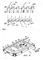
- FIG. 3 is an illustration of a higher pitched note that is synthesized from a lower pitched analysis waveform, illustrating replication of an analysis period, according to an aspect of the present invention.
- Analysis waveform 300 has timing marks 304a-n computed that coincide with each period, such as period 300a. The timing marks are used as indexes during the synthesis calculations, which will be described in more detail later.
- Synthesis waveform 302 has a set of timing marks 306a-n computed to correspond to the periods that are to be synthesized, such as 302a. For each period, samples are selected from the closest time-line wise corresponding analysis period. For example, for synthesis period 302a, samples are selected from corresponding analysis period 300a.
- synthesis waveform 302 Since the pitch of synthesis waveform 302 is higher than analysis waveform 300, a time skew develops. In order to compensate for this time skew, two synthesis periods 312, 314 are formed by selecting samples from the same analysis period 310 whenever the time skew becomes approximately one period in length.
- the relation between the analysis time-mark index and the synthesis time-mark index is a multiplication factor.
- Ks T s / T a
- the T1 time-mark set is computed and corresponds to 20ms of the beginning of the waveform.
- the T2 time-mark set corresponds to the decay portion of the waveform, which in this case includes time-marks in the set [20ms...50ms].
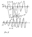
- FIG. 4 is an illustration of another embodiment of the invention illustrating the use of two windows to form a synthesized waveform 410.
- Each window is a Hanning window.
- a Hanning window is a cosinous digital manipulation of a sampled signal which forces the beginning and ending samples of the time record to zero amplitude.
- Other embodiments of the invention may use other known types of windows, such as Hamming, triangular, etc.
- the random number generator gives an even value the samples are copied with the respect of the time sequence, that is, the first sample is A[tm_ia] and the last one is A[tm_ia+tsa-1]. Otherwise, if the random data is odd the time sequence is inverted, such that the first synthesis data is A[tm_ia+tsa-1] and the last one is A[tm_ia].
- FIG. 6A is a flow diagram illustrating how a set of analysis waveforms are collected.
- step 600 a single note from an instrument is sampled to form an instrumentally correct digital analysis waveform.
- the sampling rate is selected according to the expected use. For telephone type devices, a sampling rate of 8kHz is typically used. For a high quality audio synthesizer, a sample rate of 40khz might be used, for example.
- step 802 MPU 102 loads a file that contains a requested musical score into shared memory 112.
- a musical score file is referred to herein as an E2 file.
- the E2 file format is a compressed binary file in order to use as least possible memory in the MPU address space.
- the data rate is about 4 bytes per synthesized note. This size can be greater with optional sound generation effects like: pitch bend, volume tremolo and vibrato.
- the time stamp byte is followed by two bytes (16 bits) of note definition data having the following format: six bits for frequency selection, three bits for amplitude, three bits for the analysis wave selection, and four bits for the duration.
- the MCU reads the first byte of the data stream, then waits a time period according to the time stamp before loading the dual port memory interface with the note definition data: two bytes or six bytes if the extension bit is set. Then the MCU reads the next time stamp byte indicating a delay for the next note before loading the next set of note definition data. For notes to be played in parallel, the time delay could be zero.
- DSP 104 reads each set of note definition data provided by the MPU from the E2 file and computes the frequency, amplitude, and duration of each note to synthesize using the respective fields in the two byte note definition data. DSP 104 then computes a set of synthesis time marks for each note.
- Radio frequency (RF) circuitry (not shown) is connected to an aerial 18 and is driven by megacell 100 as a DSP private peripheral 140 and provides a wireless network link.
- Connector 20 is connected to a cable adaptor-modem (not shown) and thence to megacell 100 as a DSP private peripheral 140 provides a wired network link for use during stationary usage in an office environment, for example.
- a short distance wireless link 23 is also "connected" to earpiece 22 and is driven by a low power transmitter (not shown) connected to megacell 100 as a DSP private peripheral 140.
- Microphone 24 is similarly connected to megacell 100 such that two-way audio information can be exchanged with other users on the wireless or wired network using microphone 24 and wireless earpiece 22.
Landscapes
- Engineering & Computer Science (AREA)
- Physics & Mathematics (AREA)
- Multimedia (AREA)
- Acoustics & Sound (AREA)
- General Engineering & Computer Science (AREA)
- Mathematical Analysis (AREA)
- Pure & Applied Mathematics (AREA)
- Mathematical Physics (AREA)
- Mathematical Optimization (AREA)
- General Physics & Mathematics (AREA)
- Algebra (AREA)
- Electrophonic Musical Instruments (AREA)
- Telephone Function (AREA)
- Toys (AREA)
Claims (13)
- Procédé pour synthétiser de la musique dans un système numérique, comprenant les étapes consistant à :accéder à une forme d'onde d'analyse numérique ayant une première durée, une première hauteur, une première partie d'attaque et une première partie d'amortissement ;déterminer une deuxième durée et une deuxième hauteur pour une forme d'onde de synthèse ;calculer des premiers repères de synchronisation pour la forme d'onde d'analyse de telle sorte que les premiers repères de synchronisation correspondent à la périodicité de la forme d'onde d'analyse ;calculer des deuxièmes repères de synchronisation pour la forme d'onde de synthèse de telle sorte que les deuxièmes repères de synchronisation correspondent à la périodicité de la forme d'onde de synthèse ; etcalculer des échantillons pour chaque période de la forme d'onde de synthèse définie par les deuxièmes repères de synchronisation adjacents en utilisant des échantillons choisis parmi une période correspondante de la forme d'onde d'analyse définie par les premiers repères de synchronisation adjacents afin de former la forme d'onde de synthèse ayant la deuxième hauteur, la deuxième durée, une deuxième partie d'attaque et une deuxième partie d'amortissement.
- Procédé selon la revendication 1, dans lequel l'étape de calcul des échantillons pour chaque période comprend en outre les étapes consistant à :calculer un ensemble d'échantillons pour une période m en utilisant une première fenêtre cosinus ;calculer un ensemble d'échantillons pour une période m - 1 en utilisant une deuxième fenêtre cosinus ; etcombiner l'ensemble d'échantillons pour la période m et l'ensemble d'échantillons pour la période m - 1 en utilisant une fonction de pondération.
- Procédé selon la revendication 2, dans lequel la première fenêtre cosinus fonctionne sur deux périodes adjacentes et la deuxième fenêtre cosinus fonctionne sur deux périodes adjacentes décalées d'une période à partir de la première fenêtre cosinus.
- Procédé selon l'une quelconque des revendications 2 ou 3, comprenant en outre les étapes consistant à :inverser l'un choisi de l'ensemble d'échantillons avant l'étape de combinaison des ensembles d'échantillons.
- Procédé selon la revendication 4, dans lequel l'étape d'inversion est réalisée uniquement lorsque deux périodes consécutives de la forme d'onde de synthèse sont formées en utilisant les mêmes périodes de la forme d'onde d'analyse ; et
dans lequel l'étape d'inversion réagit à un générateur de nombres aléatoires. - Procédé selon l'une quelconque des revendications précédentes, dans lequel l'étape de calcul des échantillons comprend la formation de la forme d'onde de synthèse de telle sorte que la deuxième partie d'attaque a une durée approximativement égale à la durée de la première partie d'attaque.
- Procédé selon l'une quelconque des revendications précédentes, dans lequel l'étape de calcul des échantillons comprend la formation de la forme d'onde de synthèse de telle sorte que la deuxième partie d'amortissement est formée en déformant dans le temps la première partie d'amortissement.
- Procédé selon l'une quelconque des revendications précédentes, dans lequel la deuxième hauteur est choisie dans une plage d'au moins plus ou moins une octave autour de la première hauteur.
- Procédé selon l'une quelconque des revendications précédentes, dans lequel l'étape d'accès à la forme d'onde d'analyse comprend le choix dans une pluralité de formes d'onde numériques correctes d'un point de vue instrumental correspondant à une pluralité d'instruments.
- Procédé selon la revendication 9, dans lequel, pour au moins l'un de la pluralité d'instruments, les formes d'onde numériques correctes d'un point de vue instrumental n'incluent pas plus d'une forme d'onde pour une gamme d'au moins deux octaves.
- Système numérique, comprenant :une mémoire permettant de contenir une pluralité de formes d'ondes numériques correctes d'un point de vue instrumental correspondant à une pluralité d'instruments ;un premier processeur connecté à la mémoire, le premier processeur pouvant être actionné afin de stocker une partition musicale dans la mémoire ; etun deuxième processeur connecté à la mémoire, le deuxième processeur pouvant être actionné afin de synthétiser un signal de mélodie en réponse à la partition musicale en utilisant le procédé selon l'une quelconque des revendications précédentes pour chaque note de la mélodie.
- Système numérique selon la revendication 11, comprenant en outre
un dispositif audio connecté au deuxième processeur afin de jouer le signal de mélodie synthétisé. - Système numérique selon l'une quelconque des revendications 11 ou 12, dans lequel le système numérique comprend un assistant numérique personnel, comprenant en outre :un écran connecté au deuxième processeur par l'intermédiaire d'un adaptateur d' écran ;un circuit radiofréquence (RF) connecté au CPU; etune antenne connectée au circuit RF.
Priority Applications (4)
| Application Number | Priority Date | Filing Date | Title |
|---|---|---|---|
| DE60122296T DE60122296T2 (de) | 2001-05-28 | 2001-05-28 | Programmierbarer Melodienerzeuger |
| AT01401385T ATE336774T1 (de) | 2001-05-28 | 2001-05-28 | Programmierbarer melodienerzeuger |
| EP01401385A EP1262952B1 (fr) | 2001-05-28 | 2001-05-28 | Générateur programmable de mélodie |
| US09/965,141 US6965069B2 (en) | 2001-05-28 | 2001-09-26 | Programmable melody generator |
Applications Claiming Priority (1)
| Application Number | Priority Date | Filing Date | Title |
|---|---|---|---|
| EP01401385A EP1262952B1 (fr) | 2001-05-28 | 2001-05-28 | Générateur programmable de mélodie |
Publications (2)
| Publication Number | Publication Date |
|---|---|
| EP1262952A1 EP1262952A1 (fr) | 2002-12-04 |
| EP1262952B1 true EP1262952B1 (fr) | 2006-08-16 |
Family
ID=8182748
Family Applications (1)
| Application Number | Title | Priority Date | Filing Date |
|---|---|---|---|
| EP01401385A Expired - Lifetime EP1262952B1 (fr) | 2001-05-28 | 2001-05-28 | Générateur programmable de mélodie |
Country Status (4)
| Country | Link |
|---|---|
| US (1) | US6965069B2 (fr) |
| EP (1) | EP1262952B1 (fr) |
| AT (1) | ATE336774T1 (fr) |
| DE (1) | DE60122296T2 (fr) |
Families Citing this family (8)
| Publication number | Priority date | Publication date | Assignee | Title |
|---|---|---|---|---|
| US7551894B2 (en) * | 2003-10-07 | 2009-06-23 | Phonak Communications Ag | Wireless microphone |
| US7720677B2 (en) * | 2005-11-03 | 2010-05-18 | Coding Technologies Ab | Time warped modified transform coding of audio signals |
| US20080299906A1 (en) * | 2007-06-04 | 2008-12-04 | Topway Electrical Appliance Company | Emulating playing apparatus of simulating games |
| JP5651945B2 (ja) * | 2009-12-04 | 2015-01-14 | ヤマハ株式会社 | 音響処理装置 |
| CN102325218B (zh) * | 2011-08-10 | 2013-12-25 | 深圳市无线开锋科技有限公司 | 声控变换手机应用动态显示效果的方法及装置 |
| US9294855B2 (en) * | 2013-01-02 | 2016-03-22 | Samsung Electronics Co., Ltd. | Apparatus and method for processing audio signal |
| US8847054B2 (en) * | 2013-01-31 | 2014-09-30 | Dhroova Aiylam | Generating a synthesized melody |
| US11756516B2 (en) * | 2020-12-09 | 2023-09-12 | Matthew DeWall | Anatomical random rhythm generator |
Family Cites Families (15)
| Publication number | Priority date | Publication date | Assignee | Title |
|---|---|---|---|---|
| JPH0631989B2 (ja) * | 1985-11-14 | 1994-04-27 | ロ−ランド株式会社 | 電子楽器の波形発生装置 |
| US5086475A (en) * | 1988-11-19 | 1992-02-04 | Sony Corporation | Apparatus for generating, recording or reproducing sound source data |
| US5329062A (en) * | 1990-07-31 | 1994-07-12 | Casio Computer Co., Ltd. | Method of recording/reproducing waveform and apparatus for reproducing waveform |
| US5347478A (en) * | 1991-06-09 | 1994-09-13 | Yamaha Corporation | Method of and device for compressing and reproducing waveform data |
| US6025553A (en) * | 1993-05-18 | 2000-02-15 | Capital Bridge Co. Ltd. | Portable music performance device |
| IT1266943B1 (it) * | 1994-09-29 | 1997-01-21 | Cselt Centro Studi Lab Telecom | Procedimento di sintesi vocale mediante concatenazione e parziale sovrapposizione di forme d'onda. |
| US5864812A (en) * | 1994-12-06 | 1999-01-26 | Matsushita Electric Industrial Co., Ltd. | Speech synthesizing method and apparatus for combining natural speech segments and synthesized speech segments |
| GB2296846A (en) * | 1995-01-07 | 1996-07-10 | Ibm | Synthesising speech from text |
| US5567901A (en) * | 1995-01-18 | 1996-10-22 | Ivl Technologies Ltd. | Method and apparatus for changing the timbre and/or pitch of audio signals |
| US5814750A (en) * | 1995-11-09 | 1998-09-29 | Chromatic Research, Inc. | Method for varying the pitch of a musical tone produced through playback of a stored waveform |
| US5828994A (en) * | 1996-06-05 | 1998-10-27 | Interval Research Corporation | Non-uniform time scale modification of recorded audio |
| BE1010336A3 (fr) * | 1996-06-10 | 1998-06-02 | Faculte Polytechnique De Mons | Procede de synthese de son. |
| US5744739A (en) * | 1996-09-13 | 1998-04-28 | Crystal Semiconductor | Wavetable synthesizer and operating method using a variable sampling rate approximation |
| KR100269255B1 (ko) * | 1997-11-28 | 2000-10-16 | 정선종 | 유성음 신호에서 성문 닫힘 구간 신호의 가변에의한 피치 수정방법 |
| US6124542A (en) * | 1999-07-08 | 2000-09-26 | Ati International Srl | Wavefunction sound sampling synthesis |
-
2001
- 2001-05-28 AT AT01401385T patent/ATE336774T1/de not_active IP Right Cessation
- 2001-05-28 EP EP01401385A patent/EP1262952B1/fr not_active Expired - Lifetime
- 2001-05-28 DE DE60122296T patent/DE60122296T2/de not_active Expired - Lifetime
- 2001-09-26 US US09/965,141 patent/US6965069B2/en not_active Expired - Lifetime
Also Published As
| Publication number | Publication date |
|---|---|
| US6965069B2 (en) | 2005-11-15 |
| DE60122296D1 (de) | 2006-09-28 |
| DE60122296T2 (de) | 2007-08-30 |
| EP1262952A1 (fr) | 2002-12-04 |
| ATE336774T1 (de) | 2006-09-15 |
| US20020177997A1 (en) | 2002-11-28 |
Similar Documents
| Publication | Publication Date | Title |
|---|---|---|
| US6298322B1 (en) | Encoding and synthesis of tonal audio signals using dominant sinusoids and a vector-quantized residual tonal signal | |
| Cook | Real sound synthesis for interactive applications | |
| US5744742A (en) | Parametric signal modeling musical synthesizer | |
| US20070289432A1 (en) | Creating music via concatenative synthesis | |
| Massie | Wavetable sampling synthesis | |
| Jensen | The timbre model | |
| EP1262952B1 (fr) | Générateur programmable de mélodie | |
| EP0357096A1 (fr) | Instrument de musique électronique utilisant un système d'intervalles de gamme évitant les conflits d'harmoniques | |
| JP2006146095A (ja) | データ合成装置およびデータ合成処理のプログラム | |
| Fitz | A new algorithm for bandwidth association in bandwidth-enhanced additive sound modeling | |
| US7038119B2 (en) | Dynamic control of processing load in a wavetable synthesizer | |
| US20060217984A1 (en) | Critical band additive synthesis of tonal audio signals | |
| JP2619242B2 (ja) | 時変スペクトルを有する楽音を発生する電子楽器 | |
| JP2606791B2 (ja) | 楽音発生用のディジタル信号処理装置 | |
| CN100533551C (zh) | 在嵌入式器件中产生敲打声 | |
| JPH08211879A (ja) | 音響シミュレーション用システム、装置並びに方法 | |
| Pekonen | Computationally efficient music synthesis–methods and sound design | |
| Jensen | Perceptual and physical aspects of musical sounds | |
| JP3692954B2 (ja) | 楽曲データ編集プログラム、楽曲データ編集方法および装置 | |
| JP3304709B2 (ja) | 楽音信号分析方法 | |
| JP5533021B2 (ja) | 音響信号の符号化方法および装置 | |
| JP3706232B2 (ja) | 楽音生成装置及び楽音生成方法 | |
| Mohr | Music analysis/synthesis by optimized multiple wavetable interpolation | |
| JP3637191B2 (ja) | 楽音生成装置及び楽音生成方法 | |
| JPH0519768A (ja) | 楽音合成装置 |
Legal Events
| Date | Code | Title | Description |
|---|---|---|---|
| PUAI | Public reference made under article 153(3) epc to a published international application that has entered the european phase |
Free format text: ORIGINAL CODE: 0009012 |
|
| AK | Designated contracting states |
Kind code of ref document: A1 Designated state(s): AT BE CH CY DE DK ES FI FR GB GR IE IT LI LU MC NL PT SE TR |
|
| AX | Request for extension of the european patent |
Free format text: AL;LT;LV;MK;RO;SI |
|
| 17P | Request for examination filed |
Effective date: 20030604 |
|
| AKX | Designation fees paid |
Designated state(s): AT BE CH CY DE DK ES FI FR GB GR IE IT LI LU MC NL PT SE TR |
|
| GRAP | Despatch of communication of intention to grant a patent |
Free format text: ORIGINAL CODE: EPIDOSNIGR1 |
|
| GRAS | Grant fee paid |
Free format text: ORIGINAL CODE: EPIDOSNIGR3 |
|
| GRAA | (expected) grant |
Free format text: ORIGINAL CODE: 0009210 |
|
| AK | Designated contracting states |
Kind code of ref document: B1 Designated state(s): AT BE CH CY DE DK ES FI FR GB GR IE IT LI LU MC NL PT SE TR |
|
| PG25 | Lapsed in a contracting state [announced via postgrant information from national office to epo] |
Ref country code: IT Free format text: LAPSE BECAUSE OF FAILURE TO SUBMIT A TRANSLATION OF THE DESCRIPTION OR TO PAY THE FEE WITHIN THE PRESCRIBED TIME-LIMIT;WARNING: LAPSES OF ITALIAN PATENTS WITH EFFECTIVE DATE BEFORE 2007 MAY HAVE OCCURRED AT ANY TIME BEFORE 2007. THE CORRECT EFFECTIVE DATE MAY BE DIFFERENT FROM THE ONE RECORDED. Effective date: 20060816 Ref country code: FI Free format text: LAPSE BECAUSE OF FAILURE TO SUBMIT A TRANSLATION OF THE DESCRIPTION OR TO PAY THE FEE WITHIN THE PRESCRIBED TIME-LIMIT Effective date: 20060816 Ref country code: LI Free format text: LAPSE BECAUSE OF FAILURE TO SUBMIT A TRANSLATION OF THE DESCRIPTION OR TO PAY THE FEE WITHIN THE PRESCRIBED TIME-LIMIT Effective date: 20060816 Ref country code: NL Free format text: LAPSE BECAUSE OF FAILURE TO SUBMIT A TRANSLATION OF THE DESCRIPTION OR TO PAY THE FEE WITHIN THE PRESCRIBED TIME-LIMIT Effective date: 20060816 Ref country code: CH Free format text: LAPSE BECAUSE OF FAILURE TO SUBMIT A TRANSLATION OF THE DESCRIPTION OR TO PAY THE FEE WITHIN THE PRESCRIBED TIME-LIMIT Effective date: 20060816 Ref country code: BE Free format text: LAPSE BECAUSE OF FAILURE TO SUBMIT A TRANSLATION OF THE DESCRIPTION OR TO PAY THE FEE WITHIN THE PRESCRIBED TIME-LIMIT Effective date: 20060816 Ref country code: AT Free format text: LAPSE BECAUSE OF FAILURE TO SUBMIT A TRANSLATION OF THE DESCRIPTION OR TO PAY THE FEE WITHIN THE PRESCRIBED TIME-LIMIT Effective date: 20060816 |
|
| REG | Reference to a national code |
Ref country code: GB Ref legal event code: FG4D |
|
| REG | Reference to a national code |
Ref country code: CH Ref legal event code: EP |
|
| REG | Reference to a national code |
Ref country code: IE Ref legal event code: FG4D |
|
| REF | Corresponds to: |
Ref document number: 60122296 Country of ref document: DE Date of ref document: 20060928 Kind code of ref document: P |
|
| PG25 | Lapsed in a contracting state [announced via postgrant information from national office to epo] |
Ref country code: SE Free format text: LAPSE BECAUSE OF FAILURE TO SUBMIT A TRANSLATION OF THE DESCRIPTION OR TO PAY THE FEE WITHIN THE PRESCRIBED TIME-LIMIT Effective date: 20061116 Ref country code: DK Free format text: LAPSE BECAUSE OF FAILURE TO SUBMIT A TRANSLATION OF THE DESCRIPTION OR TO PAY THE FEE WITHIN THE PRESCRIBED TIME-LIMIT Effective date: 20061116 |
|
| PG25 | Lapsed in a contracting state [announced via postgrant information from national office to epo] |
Ref country code: ES Free format text: LAPSE BECAUSE OF FAILURE TO SUBMIT A TRANSLATION OF THE DESCRIPTION OR TO PAY THE FEE WITHIN THE PRESCRIBED TIME-LIMIT Effective date: 20061127 |
|
| ET | Fr: translation filed | ||
| PG25 | Lapsed in a contracting state [announced via postgrant information from national office to epo] |
Ref country code: PT Free format text: LAPSE BECAUSE OF FAILURE TO SUBMIT A TRANSLATION OF THE DESCRIPTION OR TO PAY THE FEE WITHIN THE PRESCRIBED TIME-LIMIT Effective date: 20070116 |
|
| NLV1 | Nl: lapsed or annulled due to failure to fulfill the requirements of art. 29p and 29m of the patents act | ||
| REG | Reference to a national code |
Ref country code: CH Ref legal event code: PL |
|
| PLBE | No opposition filed within time limit |
Free format text: ORIGINAL CODE: 0009261 |
|
| STAA | Information on the status of an ep patent application or granted ep patent |
Free format text: STATUS: NO OPPOSITION FILED WITHIN TIME LIMIT |
|
| 26N | No opposition filed |
Effective date: 20070518 |
|
| PG25 | Lapsed in a contracting state [announced via postgrant information from national office to epo] |
Ref country code: MC Free format text: LAPSE BECAUSE OF NON-PAYMENT OF DUE FEES Effective date: 20070531 |
|
| PG25 | Lapsed in a contracting state [announced via postgrant information from national office to epo] |
Ref country code: GR Free format text: LAPSE BECAUSE OF FAILURE TO SUBMIT A TRANSLATION OF THE DESCRIPTION OR TO PAY THE FEE WITHIN THE PRESCRIBED TIME-LIMIT Effective date: 20061117 |
|
| PG25 | Lapsed in a contracting state [announced via postgrant information from national office to epo] |
Ref country code: IE Free format text: LAPSE BECAUSE OF NON-PAYMENT OF DUE FEES Effective date: 20070528 |
|
| PG25 | Lapsed in a contracting state [announced via postgrant information from national office to epo] |
Ref country code: LU Free format text: LAPSE BECAUSE OF NON-PAYMENT OF DUE FEES Effective date: 20070528 Ref country code: CY Free format text: LAPSE BECAUSE OF FAILURE TO SUBMIT A TRANSLATION OF THE DESCRIPTION OR TO PAY THE FEE WITHIN THE PRESCRIBED TIME-LIMIT Effective date: 20060816 |
|
| PG25 | Lapsed in a contracting state [announced via postgrant information from national office to epo] |
Ref country code: TR Free format text: LAPSE BECAUSE OF FAILURE TO SUBMIT A TRANSLATION OF THE DESCRIPTION OR TO PAY THE FEE WITHIN THE PRESCRIBED TIME-LIMIT Effective date: 20060816 |
|
| REG | Reference to a national code |
Ref country code: FR Ref legal event code: PLFP Year of fee payment: 16 |
|
| REG | Reference to a national code |
Ref country code: FR Ref legal event code: PLFP Year of fee payment: 17 |
|
| PGFP | Annual fee paid to national office [announced via postgrant information from national office to epo] |
Ref country code: DE Payment date: 20170531 Year of fee payment: 17 Ref country code: GB Payment date: 20170426 Year of fee payment: 17 Ref country code: FR Payment date: 20170418 Year of fee payment: 17 |
|
| REG | Reference to a national code |
Ref country code: DE Ref legal event code: R119 Ref document number: 60122296 Country of ref document: DE |
|
| GBPC | Gb: european patent ceased through non-payment of renewal fee |
Effective date: 20180528 |
|
| PG25 | Lapsed in a contracting state [announced via postgrant information from national office to epo] |
Ref country code: FR Free format text: LAPSE BECAUSE OF NON-PAYMENT OF DUE FEES Effective date: 20180531 Ref country code: GB Free format text: LAPSE BECAUSE OF NON-PAYMENT OF DUE FEES Effective date: 20180528 Ref country code: DE Free format text: LAPSE BECAUSE OF NON-PAYMENT OF DUE FEES Effective date: 20181201 |