EP1263010A1 - Interrupteur à clef avec commande à câble - Google Patents
Interrupteur à clef avec commande à câble Download PDFInfo
- Publication number
- EP1263010A1 EP1263010A1 EP01112625A EP01112625A EP1263010A1 EP 1263010 A1 EP1263010 A1 EP 1263010A1 EP 01112625 A EP01112625 A EP 01112625A EP 01112625 A EP01112625 A EP 01112625A EP 1263010 A1 EP1263010 A1 EP 1263010A1
- Authority
- EP
- European Patent Office
- Prior art keywords
- key
- key switch
- switch according
- housing
- front plate
- Prior art date
- Legal status (The legal status is an assumption and is not a legal conclusion. Google has not performed a legal analysis and makes no representation as to the accuracy of the status listed.)
- Granted
Links
- 238000003780 insertion Methods 0.000 claims abstract description 24
- 230000037431 insertion Effects 0.000 claims abstract description 24
- 238000007789 sealing Methods 0.000 claims description 8
- 230000002787 reinforcement Effects 0.000 claims description 6
- 238000005253 cladding Methods 0.000 claims description 5
- 230000000295 complement effect Effects 0.000 claims description 2
- 230000015572 biosynthetic process Effects 0.000 claims 1
- 238000006073 displacement reaction Methods 0.000 claims 1
- 238000011161 development Methods 0.000 description 3
- 230000018109 developmental process Effects 0.000 description 3
- 238000005553 drilling Methods 0.000 description 3
- 230000008719 thickening Effects 0.000 description 3
- 230000000903 blocking effect Effects 0.000 description 2
- 230000003993 interaction Effects 0.000 description 2
- 230000007935 neutral effect Effects 0.000 description 2
- 238000010276 construction Methods 0.000 description 1
- 230000002265 prevention Effects 0.000 description 1
- 230000003014 reinforcing effect Effects 0.000 description 1
- 230000001960 triggered effect Effects 0.000 description 1
Images


Classifications
-
- H—ELECTRICITY
- H01—ELECTRIC ELEMENTS
- H01H—ELECTRIC SWITCHES; RELAYS; SELECTORS; EMERGENCY PROTECTIVE DEVICES
- H01H27/00—Switches operated by a removable member, e.g. key, plug or plate; Switches operated by setting members according to a single predetermined combination out of several possible settings
- H01H27/06—Key inserted and then turned to effect operation of the switch
-
- H—ELECTRICITY
- H01—ELECTRIC ELEMENTS
- H01H—ELECTRIC SWITCHES; RELAYS; SELECTORS; EMERGENCY PROTECTIVE DEVICES
- H01H27/00—Switches operated by a removable member, e.g. key, plug or plate; Switches operated by setting members according to a single predetermined combination out of several possible settings
- H01H27/06—Key inserted and then turned to effect operation of the switch
- H01H2027/066—Key inserted and then turned to effect operation of the switch having anti-tamper provisions, e.g. avoiding the removal of the lock cylinder
Definitions
- the invention relates to a cable pull key switch according to the preamble of claim 1.
- Such key switches normally work in such a way that after insertion of the key and turning the lock cylinder in one or another direction, an electrical switch is operated, which over a electric drive circuit turns on a motor, for example coupled with a movable gate that can be opened or closed is that it opens the gate in one direction of rotation when the drive is open the gate closes when the drive is in the other direction of rotation.
- a Key switch as known for example from DE-AS 22 08 019 are mainly used to open and close garage doors by means of a security key inserted into a profile half-cylinder lock, where the key is only in a single, preferably middle position can be inserted or removed, in all others Rotary positions, however, are not deducted from the lock can.
- the gate of It has already become known to be able to open the hand by means of the Key unlocking, which is a hand opening of the Tores allowed.
- One way of mechanical emergency release from electrically operated door or gate drives is that the unlocking mechanism via a Bowden cable with the housing of the Key switch connected and by a rotatable threaded pin, which is arranged in the housing of the key switch, over the Bowden cable can be triggered.
- the rotatable threaded pin is from the Front of the housing through an opening in the front panel accessible.
- a disadvantage of the known construction is that on the lock cylinder special locking tab must be mounted and that of the front panel accessible locking tab easily drilled through with a drill can be, which then the emergency release without inserting the key becomes accessible.
- the aim of the present invention is a cable pull key switch to create the genus mentioned at the beginning Safe prevention without structural changes to the cylinder lock mechanical emergency operation with the key removed is.
- the cable pull key switch according to the invention for the use of standard profile half-cylinder locks be suitable.
- an axial movement of the holding pin when in the key removal or insertion position of the Lock cylinder effectively prevented.
- the stop is useful here formed by a recess in the circumference of the holding pin.
- the design of the holding pin as a threaded pin is particularly preferred according to claim 4.
- the interaction between the beard of the cylinder lock and the threaded pin is expediently provided by providing a recess on the circumference of the threaded pin according to claim 5.
- the holding pin provided according to the invention can also be used to disassemble the key switch Allow the front panel to be removed without using a key.
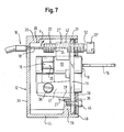
- the retaining pin cooperates with the stop surface fixed to the housing, prevent the stop and the counter surface on the housing removing the front panel after loosening the fastening screw. Only when the key is inserted, the beard by twisting the key is released from the withdrawal or insertion position and the retaining pin is screwed out of the front plate so far that it is from the stop surface on the housing is free, such a pivoting the front panel relative to the housing possible that the stop of the counter surface is released.
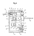
- a cable pull key switch according to the invention a square front plate 11, which in a cuboid Housing 12 is inserted, from the lower wall 44 itself 5 a tab-shaped fastening projection at a distance from the front edge 46 30 extends upwards, in which a threaded bore 31 is located with a mounting hole 32 in the front panel 11 is axially aligned.
- the front panel 11 in the fully assembled state by a sealing plate 35 and a subsequent cladding panel 36 covered, which with the openings have corresponding openings in the front panel 11.
- the cover plate 36, the sealing plate 35 and the front plate 11 are thereby attached to the housing 12 that through the with the mounting hole 32 corresponding bores 33 of the sealing plate 35 and 34 the panel 36 a bolt 45 through the mounting hole 36 is screwed into the threaded bore 31.
- a fastening tab 37 jumps from the rear of the front plate 11 into the interior of the housing 12, on which by means of a bolt 38 Profile half-cylinder lock 13 is attached.
- the front of the castle passes through an opening 14 complementary to it in the front plate 11 ( Figure 1).
- a security key 15 ( Figure 5) can be inserted in the usual way, namely only in the key withdrawal or -Einsteckposition. In this is the beard 16 ( Figure 5) of the castle in a vertically upward position.
- a reinforcement projection 43 is formed ( Figures 4, 5), which has a channel 21 ′ aligned with the bore 21.
- the actuating head 22 ' is also provided with a transverse slot 49 in which a tool or a coin is inserted for actuation can.
- the head also has a marking 50 in the form of a red dot on, which cooperates with a counter mark 51 on the trim panel 36. The normal position is not reached until after screwing in the marking 50 is aligned with the counter marking 51 is.
- the threaded pin 22 protrudes rearward from the reinforcement projection 43 before and extends in the fully screwed-in state ( Figure 5) to almost to the rear wall 39 of the housing 12.
- the threaded pin 22 has one in FIG. 5 shown normal position from the reinforcing approach 43 protruding area on one side a recess 24 which is radially from the outside to about Central axis of the threaded pin 22 is sufficient.
- the threaded pin 22 is at least in the area of the recess 24 hollow (47) to the end near the rear wall 39 To create space for a stop thickening 20, which at the end of the a bore in the rear wall 39 of the housing 12 guided core 18 ' a Bowden cable 18 is attached.
- the Bowden cable 18 provides an emergency operating device for one Not shown gate unlocking mechanism.
- the dimensioning of the threaded pin 22 and its arrangement relative to the profile half-cylinder lock 13 are such that in the shown in Figure 5 Neutral position of the lock the beard 16 largely form-fitting enters the recess 24, in particular the upper end surface 25 of the beard 16 is so close to the flat bottom of the recess 24 that a rotation of the threaded pin 22 is not possible.
- the latter has between the actuating head 22 'and the holding pin 22 a constriction 52, which acts as a predetermined breaking point, such that when trying to force the retaining pin 22 out of its normal position unscrew, the actuating head 22 'breaks off.
- the Bowden cable 18 is in a manner not shown with an emergency release for the gate operated by the key switch.
- Such an emergency release basically works in the following Wise.
- the threaded pin 22 is in the neutral position shown in FIG. 5 secured against unscrewing from the front plate 11 in that the beard 16 engages positively in the recess 24.
- a projection 29 is provided, one below Has stop surface 26, the housing-side at a short distance End region of the threaded pin 22 is opposite.
- a stop protruding downward 27 At the bottom of the Mounting tab 37 is a stop protruding downward 27, which has a stop surface 28 on the rear side of the fastening projection 30 engages behind.
- the arrangement of the stop surface 26 and the stop 27 and the counter surface 28 are such that after Unscrew the bolt 45 from the threaded bore 31 of the fastening projection 30 a removal of the front panel 11 to the front is not possible because the front plate 11 from the position shown in Figure 5 can only be tilted so far that the end region of the threaded pin 22 abuts the abutment surface 26, which is not yet sufficient for the To release stop 27 from the counter surface 28.
- the emergency actuation device is obtained in this way an additional function as a component to prevent disassembly the key switch without a key inserted beforehand.
Landscapes
- Lock And Its Accessories (AREA)
Priority Applications (2)
| Application Number | Priority Date | Filing Date | Title |
|---|---|---|---|
| EP20010112625 EP1263010B1 (fr) | 2001-05-23 | 2001-05-23 | Interrupteur à clef avec commande à câble |
| ES01112625T ES2222291T3 (es) | 2001-05-23 | 2001-05-23 | Interruptor de llave con cable de mando. |
Applications Claiming Priority (1)
| Application Number | Priority Date | Filing Date | Title |
|---|---|---|---|
| EP20010112625 EP1263010B1 (fr) | 2001-05-23 | 2001-05-23 | Interrupteur à clef avec commande à câble |
Publications (2)
| Publication Number | Publication Date |
|---|---|
| EP1263010A1 true EP1263010A1 (fr) | 2002-12-04 |
| EP1263010B1 EP1263010B1 (fr) | 2004-08-18 |
Family
ID=8177530
Family Applications (1)
| Application Number | Title | Priority Date | Filing Date |
|---|---|---|---|
| EP20010112625 Expired - Lifetime EP1263010B1 (fr) | 2001-05-23 | 2001-05-23 | Interrupteur à clef avec commande à câble |
Country Status (2)
| Country | Link |
|---|---|
| EP (1) | EP1263010B1 (fr) |
| ES (1) | ES2222291T3 (fr) |
Cited By (3)
| Publication number | Priority date | Publication date | Assignee | Title |
|---|---|---|---|---|
| EP2442337A1 (fr) | 2010-10-15 | 2012-04-18 | Sewosy, Société Par Actions Simplifiée | Dispositif de contacteur clé |
| CN111395889A (zh) * | 2020-03-30 | 2020-07-10 | 南京康尼机电股份有限公司 | 一种电钥匙开关装置 |
| CN111415835A (zh) * | 2019-01-08 | 2020-07-14 | C·鲍姆加特 | 钥匙开关 |
Families Citing this family (1)
| Publication number | Priority date | Publication date | Assignee | Title |
|---|---|---|---|---|
| EP3703022B1 (fr) * | 2019-03-01 | 2024-05-29 | Diebold Nixdorf Systems GmbH | Agencement permettant de sécuriser la fermeture d'un module de tête d'un dispositif de manipulation des papiers fiduciaires |
Citations (2)
| Publication number | Priority date | Publication date | Assignee | Title |
|---|---|---|---|---|
| US3766341A (en) * | 1973-02-20 | 1973-10-16 | Ramm Ind | Locking device |
| DE4407678A1 (de) * | 1994-03-08 | 1995-09-14 | Baumgart Ind Co Sa | Schlüsselschalter |
-
2001
- 2001-05-23 EP EP20010112625 patent/EP1263010B1/fr not_active Expired - Lifetime
- 2001-05-23 ES ES01112625T patent/ES2222291T3/es not_active Expired - Lifetime
Patent Citations (2)
| Publication number | Priority date | Publication date | Assignee | Title |
|---|---|---|---|---|
| US3766341A (en) * | 1973-02-20 | 1973-10-16 | Ramm Ind | Locking device |
| DE4407678A1 (de) * | 1994-03-08 | 1995-09-14 | Baumgart Ind Co Sa | Schlüsselschalter |
Cited By (3)
| Publication number | Priority date | Publication date | Assignee | Title |
|---|---|---|---|---|
| EP2442337A1 (fr) | 2010-10-15 | 2012-04-18 | Sewosy, Société Par Actions Simplifiée | Dispositif de contacteur clé |
| CN111415835A (zh) * | 2019-01-08 | 2020-07-14 | C·鲍姆加特 | 钥匙开关 |
| CN111395889A (zh) * | 2020-03-30 | 2020-07-10 | 南京康尼机电股份有限公司 | 一种电钥匙开关装置 |
Also Published As
| Publication number | Publication date |
|---|---|
| ES2222291T3 (es) | 2005-02-01 |
| EP1263010B1 (fr) | 2004-08-18 |
Similar Documents
| Publication | Publication Date | Title |
|---|---|---|
| EP1447500B1 (fr) | Dispositif de blocage de sécurité | |
| DE102007035218A1 (de) | Elektrisch automatisiert entriegelbares Schloss, insbesondere für schließfachartige Aufbewahrungssysteme | |
| EP0610542B1 (fr) | Serrure mortaisée en particulier pour portes d'appartement, notamment serrure avec barres coulissantes | |
| DE112007001826B4 (de) | Schlossmechanismus | |
| DE19813166A1 (de) | Türschloßanordnung, vorzugsweise Treibstangenschloßanordnung | |
| EP0653533B1 (fr) | Tige coulissante immobilisable pour serrure d'une fenêtre oscillo-battante | |
| EP1056915B1 (fr) | Serrure | |
| DE102015001960A1 (de) | Schliesszylinder mit zwei auf gleicher Achse beabstandet zueinander angeordneten Schliessnasen | |
| EP0635612B1 (fr) | Dispositif de verrouillage pour porte | |
| EP0175211A1 (fr) | Fermeture de tourniquet actionnée et arrêtée au moyen d'une clé à douille | |
| DE3806189A1 (de) | Verriegelungsvorrichtung | |
| EP1885977B1 (fr) | Dispositif de verrou de securite pour une porte, un portail ou un element similaire | |
| EP1263010B1 (fr) | Interrupteur à clef avec commande à câble | |
| DE3432981A1 (de) | Nebenschloss einer schlosseinrichtung fuer einbruchhemmende tueren | |
| EP0779404A2 (fr) | Serrure de sécurité | |
| EP0779402B1 (fr) | Serrure de sécurité | |
| EP3543436B1 (fr) | Contre-serrure pour vantail passif | |
| DE3342458C2 (fr) | ||
| EP3366873B1 (fr) | Sécurité de fenêtre/porte | |
| EP1724417B1 (fr) | Élément de serrure | |
| EP0601294A1 (fr) | Serrure complémentaire de securité pour battant de fenêtres, portes ou similaires | |
| EP0779403A1 (fr) | Serrure de sécurité | |
| DE102010022742B4 (de) | Sicherheitsschloss mit einem Schlüssel zur Umstellung der Zuhaltungen und zur Betätigung des Schließwerks | |
| EP1164238A1 (fr) | Serrure cylindrique | |
| EP1473427B1 (fr) | Dispositif de blocage de sécurité |
Legal Events
| Date | Code | Title | Description |
|---|---|---|---|
| PUAI | Public reference made under article 153(3) epc to a published international application that has entered the european phase |
Free format text: ORIGINAL CODE: 0009012 |
|
| AK | Designated contracting states |
Kind code of ref document: A1 Designated state(s): AT BE CH CY DE DK ES FI FR GB GR IE IT LI LU MC NL PT SE TR |
|
| AX | Request for extension of the european patent |
Free format text: AL;LT;LV;MK;RO;SI |
|
| AKX | Designation fees paid | ||
| 17P | Request for examination filed |
Effective date: 20030729 |
|
| RBV | Designated contracting states (corrected) |
Designated state(s): ES FR IT |
|
| REG | Reference to a national code |
Ref country code: DE Ref legal event code: 8566 |
|
| GRAP | Despatch of communication of intention to grant a patent |
Free format text: ORIGINAL CODE: EPIDOSNIGR1 |
|
| GRAS | Grant fee paid |
Free format text: ORIGINAL CODE: EPIDOSNIGR3 |
|
| GRAA | (expected) grant |
Free format text: ORIGINAL CODE: 0009210 |
|
| AK | Designated contracting states |
Kind code of ref document: B1 Designated state(s): ES FR IT |
|
| REG | Reference to a national code |
Ref country code: IE Ref legal event code: FG4D Free format text: GERMAN |
|
| REG | Reference to a national code |
Ref country code: ES Ref legal event code: FG2A Ref document number: 2222291 Country of ref document: ES Kind code of ref document: T3 |
|
| REG | Reference to a national code |
Ref country code: IE Ref legal event code: FD4D |
|
| ET | Fr: translation filed | ||
| PLBE | No opposition filed within time limit |
Free format text: ORIGINAL CODE: 0009261 |
|
| STAA | Information on the status of an ep patent application or granted ep patent |
Free format text: STATUS: NO OPPOSITION FILED WITHIN TIME LIMIT |
|
| 26N | No opposition filed |
Effective date: 20050519 |
|
| PGFP | Annual fee paid to national office [announced via postgrant information from national office to epo] |
Ref country code: ES Payment date: 20100525 Year of fee payment: 10 |
|
| REG | Reference to a national code |
Ref country code: ES Ref legal event code: FD2A Effective date: 20130404 |
|
| PG25 | Lapsed in a contracting state [announced via postgrant information from national office to epo] |
Ref country code: ES Free format text: LAPSE BECAUSE OF NON-PAYMENT OF DUE FEES Effective date: 20110524 |
|
| PGFP | Annual fee paid to national office [announced via postgrant information from national office to epo] |
Ref country code: IT Payment date: 20140530 Year of fee payment: 14 |
|
| PGFP | Annual fee paid to national office [announced via postgrant information from national office to epo] |
Ref country code: FR Payment date: 20140530 Year of fee payment: 14 |
|
| PG25 | Lapsed in a contracting state [announced via postgrant information from national office to epo] |
Ref country code: IT Free format text: LAPSE BECAUSE OF NON-PAYMENT OF DUE FEES Effective date: 20150523 |
|
| REG | Reference to a national code |
Ref country code: FR Ref legal event code: ST Effective date: 20160129 |
|
| PG25 | Lapsed in a contracting state [announced via postgrant information from national office to epo] |
Ref country code: FR Free format text: LAPSE BECAUSE OF NON-PAYMENT OF DUE FEES Effective date: 20150601 |