EP1263040A2 - Dissipateur de chaleur à haut prestation pour des dispositif électroniques - Google Patents
Dissipateur de chaleur à haut prestation pour des dispositif électroniques Download PDFInfo
- Publication number
- EP1263040A2 EP1263040A2 EP02076736A EP02076736A EP1263040A2 EP 1263040 A2 EP1263040 A2 EP 1263040A2 EP 02076736 A EP02076736 A EP 02076736A EP 02076736 A EP02076736 A EP 02076736A EP 1263040 A2 EP1263040 A2 EP 1263040A2
- Authority
- EP
- European Patent Office
- Prior art keywords
- heat
- fins
- heat conducting
- fluid
- foam
- Prior art date
- Legal status (The legal status is an assumption and is not a legal conclusion. Google has not performed a legal analysis and makes no representation as to the accuracy of the status listed.)
- Withdrawn
Links
Images


Classifications
-
- F—MECHANICAL ENGINEERING; LIGHTING; HEATING; WEAPONS; BLASTING
- F28—HEAT EXCHANGE IN GENERAL
- F28F—DETAILS OF HEAT-EXCHANGE AND HEAT-TRANSFER APPARATUS, OF GENERAL APPLICATION
- F28F3/00—Plate-like or laminated elements; Assemblies of plate-like or laminated elements
- F28F3/02—Elements or assemblies thereof with means for increasing heat-transfer area, e.g. with fins, with recesses, with corrugations
-
- F—MECHANICAL ENGINEERING; LIGHTING; HEATING; WEAPONS; BLASTING
- F28—HEAT EXCHANGE IN GENERAL
- F28F—DETAILS OF HEAT-EXCHANGE AND HEAT-TRANSFER APPARATUS, OF GENERAL APPLICATION
- F28F13/00—Arrangements for modifying heat-transfer, e.g. increasing, decreasing
- F28F13/003—Arrangements for modifying heat-transfer, e.g. increasing, decreasing by using permeable mass, perforated or porous materials
-
- H—ELECTRICITY
- H10—SEMICONDUCTOR DEVICES; ELECTRIC SOLID-STATE DEVICES NOT OTHERWISE PROVIDED FOR
- H10W—GENERIC PACKAGES, INTERCONNECTIONS, CONNECTORS OR OTHER CONSTRUCTIONAL DETAILS OF DEVICES COVERED BY CLASS H10
- H10W40/00—Arrangements for thermal protection or thermal control
- H10W40/20—Arrangements for cooling
- H10W40/22—Arrangements for cooling characterised by their shape, e.g. having conical or cylindrical projections
- H10W40/226—Arrangements for cooling characterised by their shape, e.g. having conical or cylindrical projections characterised by projecting parts, e.g. fins to increase surface area
- H10W40/228—Arrangements for cooling characterised by their shape, e.g. having conical or cylindrical projections characterised by projecting parts, e.g. fins to increase surface area the projecting parts being wire-shaped or pin-shaped
-
- H—ELECTRICITY
- H10—SEMICONDUCTOR DEVICES; ELECTRIC SOLID-STATE DEVICES NOT OTHERWISE PROVIDED FOR
- H10W—GENERIC PACKAGES, INTERCONNECTIONS, CONNECTORS OR OTHER CONSTRUCTIONAL DETAILS OF DEVICES COVERED BY CLASS H10
- H10W40/00—Arrangements for thermal protection or thermal control
- H10W40/20—Arrangements for cooling
- H10W40/25—Arrangements for cooling characterised by their materials
- H10W40/251—Organics
-
- H—ELECTRICITY
- H10—SEMICONDUCTOR DEVICES; ELECTRIC SOLID-STATE DEVICES NOT OTHERWISE PROVIDED FOR
- H10W—GENERIC PACKAGES, INTERCONNECTIONS, CONNECTORS OR OTHER CONSTRUCTIONAL DETAILS OF DEVICES COVERED BY CLASS H10
- H10W40/00—Arrangements for thermal protection or thermal control
- H10W40/20—Arrangements for cooling
- H10W40/25—Arrangements for cooling characterised by their materials
- H10W40/257—Arrangements for cooling characterised by their materials having a heterogeneous or anisotropic structure, e.g. powder or fibres in a matrix, wire mesh or porous structures
-
- Y—GENERAL TAGGING OF NEW TECHNOLOGICAL DEVELOPMENTS; GENERAL TAGGING OF CROSS-SECTIONAL TECHNOLOGIES SPANNING OVER SEVERAL SECTIONS OF THE IPC; TECHNICAL SUBJECTS COVERED BY FORMER USPC CROSS-REFERENCE ART COLLECTIONS [XRACs] AND DIGESTS
- Y10—TECHNICAL SUBJECTS COVERED BY FORMER USPC
- Y10T—TECHNICAL SUBJECTS COVERED BY FORMER US CLASSIFICATION
- Y10T29/00—Metal working
- Y10T29/49—Method of mechanical manufacture
- Y10T29/4935—Heat exchanger or boiler making
Definitions
- the present invention is directed to heat sinks primarily for use in dissipating waste heat generated by electrical and/or electronic components and assemblies.
- These heat sinks include a heat spreader plate and an assembly of heat conducting fins and reticulated foam structures that are bonded together.
- the foam block may be a continuous single block within the space between two adjacent fins along the length of the fins or may be an array of short-length blocks having intervening gaps along the length of the fins.
- Electronic components are connected to one surface of the spreader plate with the assembly of fins and foam connected to another surface of the spreader plate in contact with a cooling fluid.
- FIG. 1 A typical heat sink for electrical or electronic components is depicted in Fig. 1.
- the heat sink includes a heat spreader plate 10 to which metal fins 12 are attached.
- An electronic component is attached to face 14 of spreader plate 10 and a cooling fluid 16, such as air or water, is passed across fins 12 to dissipate the heat generated by the electronic component.
- a cooling fluid 16 such as air or water
- the spreader plate size i.e., area
- Fin spacing and fin height are usually determined by known methods such as numerical modeling.
- heat sinks for low power density microelectronics such as computer chips
- the chip is bonded directly onto the heat sink via an interface.
- More advanced heat sinks for high power density computer chips employ a separate spreader plate onto which is bonded the chip via an interface. The spreader plate/chip assembly is then bonded onto the heat sink via another interface. The presence of two interfaces significantly increases the overall thermal resistance to heat transfer from the chip to the coolant flow.
- heat exchange In demanding applications, the method of heat exchange is usually forced convection to the cooling fluid. In such systems, heat exchange can be improved by increasing the fin surface area exposed to the cooling fluid. This is accomplished by increasing the number of the fins per unit volume.
- Reticulated foams are also known in the art for their ability to conduct heat such as the metal foams disclosed in U.S. Pat. Nos. 3,616,841 and 3,946,039 to Walz, and the ceramic foams disclosed in U.S. Pat. No. 4,808,558 to Park et al. Metal foams have been sold under the trade name DUOCEL available from Energy Research and Generation, Inc., Oakland, California.
- metal and ceramic reticulated foams have not been adapted for use in heat sinks for dissipating waste heat from electronic components.
- these structures especially when comprised of metal, make excellent heat exchangers because of their conductivity and their extremely high surface area to volume ratio.
- reticulated foam has up to 15,625 open cells per square inch.
- Reticulated foam is far more porous and has far more surface area per unit volume (1600 square feet/cubic foot) than heat exchangers having other structures.
- the pressure drop of fluids flowing through reticulated foam is also relatively low so that movement of a cooling fluid through the foam is practical.
- Bastawros' results were based on thermal and hydraulic measurements (on an open cell aluminum alloy foam having a pore size of 30 pores per inch) used in conjunction with a model based upon a bank of cylinders in cross-flow to understand the effect of various foam morphologies.
- the model prediction was extrapolated to examine the trade-off between heat removal and pressure drop.
- the measurements showed that a high performance cellular aluminum heat sink (i.e., aluminum foam) removed 2-3 times the usual heat flux removed by a pin-fin array with only a moderate increase in pressure drop.
- a range of new heat sinks for electrical and electronic components is herein presented that provides for space-efficient heat exchange with low thermal resistance. These heat sinks are capable of removing the increased waste heat flux generated by today's higher power electronic systems.
- heat sinks of the present invention comprise a spreader plate, at least two fins and at least one porous reticulated foam block that fills the space between the fins.
- the foam block may be a continuous single block within the space between two adjacent fins along the length of the fins or may be an array of short-length blocks having intervening gaps in-between the blocks along the length of the fins. All materials are made from a heat conducting material.
- the fins and foam blocks form an assembly that is connected to one surface of the spreader plate. Electronic components to be cooled are preferably connected to an opposing surface of the spreader plate, but may be connected to any surface of the spreader plate suited for heat transfer.
- the preferred dimensional length is defined for the foam blocks used, whether they comprise continuous single foam blocks (hereinafter referred to as “continuous block”) or an array of short-length foam blocks (hereinafter referred to as "interrupted block”) along each fin length.
- the present invention also defines a relationship for determining the optimum interrupted block length when such an array is selected.
- the present invention further defines the preferred dimensional relationships for establishing the optimum fin spacing and fin height for the heat sinks provided herein. Devices produced using these dimensional relationships find particular use in cooling microelectronic components such as microprocessors.
- heat sinks that use a combination of solid non-porous fins and highly porous reticulated foam can provide improved performance over known applications that use one or the other. It is fully contemplated that any combinations of fins and reticulated foam may be used in a wide variety of different applications to achieve improved cooling.
- Heat sinks of the present invention achieve very high convective heat transfer surface per unit volume.
- These heat sinks comprise a spreader plate, at least two fins and at least one porous reticulated foam block that fill the space between the fins.
- the foam block may be continuous blocks that fill the space between two adjacent fins along the length of the fins, as shown in Figs. 2A and 2B, or may be an arrays of interrupted blocks having gaps in-between successive blocks along the length of the fins, as shown in Figs. 3A and 3B.
- This basic structure may be expanded to any configuration comprising foam blocks in between at least two fins that are mounted onto the surface of a spreader plate.
- Cooling fluid Primary heat transfer to the cooling fluid is by convection from the foam, with the fins and spreader plate being used to conduct heat from the connected heat source (i.e., the electronic component) into the foam.
- the connected heat source i.e., the electronic component
- air-to-air heat exchange i.e., where air is being used as the cooling fluid
- ambient air may be drawn in through the foam's open vertical side walls and exhausted through the foam's top surface, or vice versa.
- the device comprises a heat spreader plate 20, with fins 22 and reticulated foam blocks 24 filling the space in-between the fins.
- the fins 22 and foam blocks 24 form an assembly that is mounted onto one surface of the spreader plate 20, leaving an opposing surface free for contact with an electronic component to be cooled.
- fins 22 are mounted so that they are substantially perpendicular to the spreader plate 20.
- Foam blocks 24 are mounted in-between fins 22 to fill the width region that defines the horizontal space between adjacent fins.
- the foam blocks 24 also preferably fill the height region that defines the vertical space between adjacent fins to the height of the fins 22.
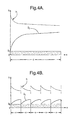
- Figs. 4A and 4B show the heat transfer characteristics of a solid substrate material bonded to foam as depicted in Figs. 4A and 4B.
- the upward sloping solid line in Fig. 4A shows the growth of the thermal boundary layer thickness ⁇ t on a substrate with a long foam block of length c in the flow direction indicated by the arrow.
- the downward sloping dashed line in Fig. 4A shows the variation of the heat transfer coefficient h over the same foam block.
- the opposing trends of the two curves indicate that as the thermal boundary thickness increases, the heat transfer coefficient decreases. In other words, as the thermal boundary thickness increases, the resistance to heat transfer increases since the thermal boundary layer thickness is a direct measure of resistance to heat transfer. The smaller the boundary layer thickness the smaller is the resistance to heat transfer.
- the upward sloping solid lines in Fig. 4B show the growth of the thermal boundary layers on a substrate with an array of short foam blocks each of length x in the flow direction indicated by the arrow.
- the dotted lines in Fig. 4B show the variation of the heat transfer coefficient h over the same array of foam blocks.
- This heat transfer coefficient curve resembles a saw tooth wave. The saw tooth nature of the heat transfer coefficient curve is due to repeated interruption of the fluid flow at the trailing edge of each short foam block, since the thermal boundary layer starts developing anew at the leading edge of the succeeding foam block.
- the overall thermal boundary layer thickness ⁇ t never gets a chance to grow very thick and consequently the heat transfer coefficient remains fairly high over the entire length of the solid substrate.
- an array of short blocks of foam, or "interrupted" blocks are used to select the desired heat transfer.
- Formulas to establish the preferred length of such interrupted blocks are provided herein. While the formulas define the preferred upper and lower thresholds for the length, longer or shorter lengths are also contemplated. In addition, lengths approaching the lower threshold are more preferred.
- the device comprises a heat spreader plate 30 that preferably includes a recessed area 31 suitable for placement and attachment of a microelectronic component such as a computer chip.
- the recessed area 31 eliminates the typical interface between the heat sink and the spreader plate used for high power density chips, thereby reducing the overall thermal resistance to heat transfer from the chip to the coolant flow.
- the device comprises fins 32 and arrays of interrupted blocks 34 having gaps 36 in-between that fill the space between the width of the fins and along at least a portion of the flow length of the fins.
- interrupted blocks are all of approximately equivalent length, it is contemplated that the blocks at each end may be shorter than any other blocks to accommodate for sizing of the selected spreader plate.
- the fins 32 and interrupted blocks 34 form an assembly that is mounted onto surface of spreader plate 30 that is opposite to the surface having the recessed area 31.
- fins 32 are mounted so that they are substantially perpendicular to the spreader plate 30.
- Interrupted blocks 34 are mounted in-between fins 32 to fill the width region that defines the horizontal space between adjacent fins leaving a gap 36 between successive interrupted blocks along the flow length of the fins as shown in Fig. 3B.
- the gap 36 between successive interrupted blocks is unimportant, but it is preferred that the gap 36 be as small as possible.
- the interrupted blocks 34 also preferably fill the height region that defines the vertical space between adjacent fins to the height of the fins 32.
- Fig. 2A and Fig. 3A depict foam blocks 24 and interrupted blocks 34 that fill the height region, it is contemplated that in alternative embodiments the blocks may partially fill or overfill the height region.
- heat sinks of the present invention are configured such that the fins 22 and 32 are substantially parallel to one another and aligned along the length of the spreader plate 20 and 30, respectively.
- the overall dimensions of the spreader plate are generally fixed based on the amount of heat to be dissipated from the surface of the heat source (such as a computer chip).
- the spreader plate surface area should be such that, for a prescribed flow rate of the cooling fluid flowing over the spreader plate, the heat from the heat source is able to spread to the edges of the spreader plate. Additional considerations may also be determinative of the spreader plate surface area such as packaging constraints.
- spreader plate surface area is selected by multiplying the surface area of the heat source with the area magnification factor.
- the area magnification factor ⁇ A s /A h represents a ratio of the surface area of the heat source A h with the surface area of the spreader plate A s .
- Typical values of ⁇ are in the range of 8 to 12, and are generally used in calculating spreader plate surface area for a given surface area of a heat source. From the standpoint of heat removal efficiency, ⁇ should be as low as possible. Highly effective heat transfer surfaces such as highly conductive fins of optimized dimensions and/or the use of heat transfer augmentation means such as reticulated foam provide for relatively low values of ⁇ .
- packaging considerations could prescribe a length of the plate in the flow direction to be 4 in. Then the width of the spreader plate will be 3 in.
- the number of fins and the fin length in the flow direction can be determined following calculation of fin spacing, a .
- the maximum number of fins n can be determined as follows.
- the width of the spreader plate is equal to the space occupied by n fins, n ⁇ f , plus the space taken up by the inter-fin gaps, ( n -1) a .
- the fin spacing a that is equal to the foam width
- fin height b that is equal to the foam height
- ⁇ is about 2.5. However, depending on heat dissipation and pressure drop considerations, higher values of ⁇ may be employed.
- an array of interrupted blocks fill the width in-between the fins and along at least a portion of the length of the fins to replace a single continuous foam block as shown in Figs. 2A and 2B.
- the foam length x of an individual short-length block in the flow direction that is needed to maintain a high heat transfer coefficient is related to the fin spacing a (and foam block width) and fin height b (and foam block height).
- the thermal boundary layer thickness ⁇ t growing from the fin wall should not exceed the value of 0.5 a . Also, it has been determined that minimizing the thermal boundary layer thickness will maximize heat transfer. In addition, it has been determined that the practical minimum value of ⁇ t is about 5% of its maximum value, or about 0.025 a . Accordingly, it is preferred that the range for the length x be selected for ⁇ t greater than about 0.025 a , more preferred that the length x be selected for a ⁇ t less than about 0.05a and most preferred that the length x be selected for ⁇ t equal to about 0.025 a . By introducing each of these value of ⁇ t into Eq. (7), the preferred range for x is thus determined according to the following:
- the fins and foam are bonded to one another and the spreader plate. While thermal bonding such as brazing is preferred, any suitable means may be employed including, for example, using a conductive epoxy to form an adhesive bond.
- a suitable thermally conductive epoxy is, for example, Thermaxx 2600K available from Ablestick, Inc.
- the fins, the foam blocks and the spreader plate are assembled and then preferably furnace-brazed to bond the foam to the fins and the spreader plate.
- the spreader plate and fins are solid and made from thermal conducting materials known in the art.
- the reticulated foam is an open cell media and also made from known thermal conducting materials.
- Preferred thermal conducting materials include aluminum, copper, graphite and aluminum-nitride ceramics.
- the spreader plate, fins and the reticulated foam may be selected from the same or different materials.
- the selected thermal conducting material for the spreader plate, fins and the reticulated foam is aluminum.
- the reticulated foam structure is available from commercial sources or may be made by methods known in the art. Suitable processes for making metal foams are disclosed in U. S. Pat. Nos. 3,616,841 and 3,946,039 to Walz, and processes for making ceramic foams are disclosed in U. S. Pat. No. 4,808,558, the teachings of which are incorporated herein by reference.
- Reticulated foam metal can be formed by the manufacturer to have many shapes, densities and cell sizes. Foam blocks as used herein may be obtained from such manufacturers or cut from larger pieces. Aluminum foams suitable for use herein are available under the tradename DUOCEL from Energy Research and Generation, Inc., Oakland, California.
- the fin length c in the flow direction dictated by the packaging and heat dissipation consideration, is 4 inches (0.3333 ft).
- the transport properties of the ambient air are as follows:
- Example 2 This example is the same as Example 1 except that the fin material has been changed from aluminum to copper.
- the fin length c in the flow direction dictated by the packaging and heat dissipation consideration, is 4 inches (0.3333 ft).
- the transport properties of the ambient air are as follows.
- Optimum fin spacing a follows Example 1.
- the length x is determined using Eq. (8).
- a preferred range for x is about 0.5837 inches to about 2.3348 inches.
- a preferred range for x is about 0.0260 inches to about 0.1040 inches.
Landscapes
- Engineering & Computer Science (AREA)
- Physics & Mathematics (AREA)
- Thermal Sciences (AREA)
- Mechanical Engineering (AREA)
- General Engineering & Computer Science (AREA)
- Chemical & Material Sciences (AREA)
- Dispersion Chemistry (AREA)
- Cooling Or The Like Of Semiconductors Or Solid State Devices (AREA)
- Cooling Or The Like Of Electrical Apparatus (AREA)
Applications Claiming Priority (2)
| Application Number | Priority Date | Filing Date | Title |
|---|---|---|---|
| US09/872,678 US6761211B2 (en) | 2000-03-14 | 2001-06-01 | High-performance heat sink for electronics cooling |
| US872678 | 2001-06-01 |
Publications (2)
| Publication Number | Publication Date |
|---|---|
| EP1263040A2 true EP1263040A2 (fr) | 2002-12-04 |
| EP1263040A3 EP1263040A3 (fr) | 2005-05-25 |
Family
ID=25360088
Family Applications (1)
| Application Number | Title | Priority Date | Filing Date |
|---|---|---|---|
| EP02076736A Withdrawn EP1263040A3 (fr) | 2001-06-01 | 2002-05-03 | Dissipateur de chaleur à haut prestation pour des dispositif électroniques |
Country Status (3)
| Country | Link |
|---|---|
| US (1) | US6761211B2 (fr) |
| EP (1) | EP1263040A3 (fr) |
| JP (1) | JP2003037226A (fr) |
Cited By (4)
| Publication number | Priority date | Publication date | Assignee | Title |
|---|---|---|---|---|
| EP1592060A1 (fr) * | 2004-04-30 | 2005-11-02 | LG Electronics Inc. | Appareil pour augmenter l'éfficacité de transfert thermique d'un article endothermique/exothermique |
| GB2437383A (en) * | 2006-04-20 | 2007-10-24 | Boeing Co | Hybrid ceramic core cold plate |
| US7905275B2 (en) | 2006-04-20 | 2011-03-15 | The Boeing Company | Ceramic foam cold plate |
| US8720828B2 (en) | 2009-12-03 | 2014-05-13 | The Boeing Company | Extended plug cold plate |
Families Citing this family (53)
| Publication number | Priority date | Publication date | Assignee | Title |
|---|---|---|---|---|
| US6840307B2 (en) * | 2000-03-14 | 2005-01-11 | Delphi Technologies, Inc. | High performance heat exchange assembly |
| US20030218057A1 (en) * | 2000-11-07 | 2003-11-27 | Craig Joseph | Electrical bus with associated porous metal heat sink and method of manufacturing same |
| US20020166654A1 (en) * | 2001-05-02 | 2002-11-14 | Smalc Martin D. | Finned Heat Sink Assemblies |
| US6606251B1 (en) | 2002-02-07 | 2003-08-12 | Cooligy Inc. | Power conditioning module |
| AU2003270882A1 (en) | 2002-09-23 | 2004-05-04 | Cooligy, Inc. | Micro-fabricated electrokinetic pump with on-frit electrode |
| US6994151B2 (en) | 2002-10-22 | 2006-02-07 | Cooligy, Inc. | Vapor escape microchannel heat exchanger |
| US7836597B2 (en) | 2002-11-01 | 2010-11-23 | Cooligy Inc. | Method of fabricating high surface to volume ratio structures and their integration in microheat exchangers for liquid cooling system |
| US7156159B2 (en) | 2003-03-17 | 2007-01-02 | Cooligy, Inc. | Multi-level microchannel heat exchangers |
| TWI300466B (en) | 2002-11-01 | 2008-09-01 | Cooligy Inc | Channeled flat plate fin heat exchange system, device and method |
| WO2004042306A2 (fr) | 2002-11-01 | 2004-05-21 | Cooligy, Inc. | Procede et appareil d'obtention de l'uniformite thermique et de refroidissement de point chaud dans un dispositif de production de chaleur |
| US7000684B2 (en) | 2002-11-01 | 2006-02-21 | Cooligy, Inc. | Method and apparatus for efficient vertical fluid delivery for cooling a heat producing device |
| US7293423B2 (en) | 2004-06-04 | 2007-11-13 | Cooligy Inc. | Method and apparatus for controlling freezing nucleation and propagation |
| US7044196B2 (en) | 2003-01-31 | 2006-05-16 | Cooligy,Inc | Decoupled spring-loaded mounting apparatus and method of manufacturing thereof |
| US7090001B2 (en) | 2003-01-31 | 2006-08-15 | Cooligy, Inc. | Optimized multiple heat pipe blocks for electronics cooling |
| US7201012B2 (en) | 2003-01-31 | 2007-04-10 | Cooligy, Inc. | Remedies to prevent cracking in a liquid system |
| US7017654B2 (en) | 2003-03-17 | 2006-03-28 | Cooligy, Inc. | Apparatus and method of forming channels in a heat-exchanging device |
| US7021369B2 (en) * | 2003-07-23 | 2006-04-04 | Cooligy, Inc. | Hermetic closed loop fluid system |
| US7591302B1 (en) | 2003-07-23 | 2009-09-22 | Cooligy Inc. | Pump and fan control concepts in a cooling system |
| US20050088823A1 (en) * | 2003-10-22 | 2005-04-28 | Kabadi Ashok N. | Variable density graphite foam heat sink |
| US6958912B2 (en) * | 2003-11-18 | 2005-10-25 | Intel Corporation | Enhanced heat exchanger |
| US7188662B2 (en) | 2004-06-04 | 2007-03-13 | Cooligy, Inc. | Apparatus and method of efficient fluid delivery for cooling a heat producing device |
| US7616444B2 (en) | 2004-06-04 | 2009-11-10 | Cooligy Inc. | Gimballed attachment for multiple heat exchangers |
| US20050274489A1 (en) * | 2004-06-10 | 2005-12-15 | Brand Joseph H | Heat exchange device and method |
| US7913719B2 (en) | 2006-01-30 | 2011-03-29 | Cooligy Inc. | Tape-wrapped multilayer tubing and methods for making the same |
| US20070227698A1 (en) * | 2006-03-30 | 2007-10-04 | Conway Bruce R | Integrated fluid pump and radiator reservoir |
| US8157001B2 (en) | 2006-03-30 | 2012-04-17 | Cooligy Inc. | Integrated liquid to air conduction module |
| US7715194B2 (en) | 2006-04-11 | 2010-05-11 | Cooligy Inc. | Methodology of cooling multiple heat sources in a personal computer through the use of multiple fluid-based heat exchanging loops coupled via modular bus-type heat exchangers |
| US7742297B2 (en) * | 2006-04-20 | 2010-06-22 | The Boeing Company | Ceramic foam electronic component cooling |
| WO2007149535A1 (fr) * | 2006-06-21 | 2007-12-27 | Ben Strauss | Nid d'abeille doté d'une fraction de parois cellulaires sensiblement poreuses |
| TW200924625A (en) | 2007-08-07 | 2009-06-01 | Cooligy Inc | Deformable duct guides that accommodate electronic connection lines |
| US8479806B2 (en) * | 2007-11-30 | 2013-07-09 | University Of Hawaii | Two-phase cross-connected micro-channel heat sink |
| US20090225514A1 (en) | 2008-03-10 | 2009-09-10 | Adrian Correa | Device and methodology for the removal of heat from an equipment rack by means of heat exchangers mounted to a door |
| US8171986B2 (en) * | 2008-04-02 | 2012-05-08 | Northrop Grumman Systems Corporation | Foam metal heat exchanger system |
| US20090314472A1 (en) * | 2008-06-18 | 2009-12-24 | Chul Ju Kim | Evaporator For Loop Heat Pipe System |
| US20090321045A1 (en) * | 2008-06-30 | 2009-12-31 | Alcatel-Lucent Technologies Inc. | Monolithic structurally complex heat sink designs |
| US8165855B2 (en) * | 2009-05-27 | 2012-04-24 | King Fahd University Of Petroleum & Minerals | Method for modeling fluid flow over porous blocks |
| DE102011078674A1 (de) * | 2011-07-05 | 2013-01-10 | Siemens Aktiengesellschaft | Kühlbauteil |
| US8611088B2 (en) | 2011-11-16 | 2013-12-17 | Cooper Technologies Company | Mechanical heat pump for an electrical housing |
| US9279626B2 (en) * | 2012-01-23 | 2016-03-08 | Honeywell International Inc. | Plate-fin heat exchanger with a porous blocker bar |
| US20140145107A1 (en) * | 2012-11-28 | 2014-05-29 | Massachusetts Institute Of Technology | Heat Exchangers Using Metallic Foams on Fins |
| WO2015157523A1 (fr) * | 2014-04-10 | 2015-10-15 | Advanced Thermal Solutions, Inc. | Dissipateur de chaleur à entrée d'écoulements multiples |
| BE1023686B1 (nl) * | 2015-11-12 | 2017-06-15 | Maes Jonker Nv | Inrichting met metaalschuim voor versnelde overdracht van warmte |
| JP6477800B2 (ja) * | 2017-08-02 | 2019-03-06 | 三菱マテリアル株式会社 | ヒートシンク |
| IL274479B2 (en) | 2017-11-06 | 2024-02-01 | Zuta Core Ltd | Systems and methods for heat exchange |
| JP7098954B2 (ja) * | 2018-02-21 | 2022-07-12 | 三菱マテリアル株式会社 | ヒートシンク |
| JP7148118B2 (ja) * | 2018-08-09 | 2022-10-05 | 国立大学法人 東京大学 | 伝熱装置 |
| CN112566439B (zh) * | 2019-09-10 | 2022-11-15 | 惠州视维新技术有限公司 | 散热器、散热器制作方法及显示装置 |
| DE102019124583B4 (de) | 2019-09-12 | 2021-12-16 | Ford Global Technologies, Llc | Lichtmodul mit Wärmeaustauschvorrichtung mit geschlossenporigem Metallschaum |
| US11276624B2 (en) * | 2019-12-17 | 2022-03-15 | Infineon Technologies Austria Ag | Semiconductor device power metallization layer with stress-relieving heat sink structure |
| WO2022016263A1 (fr) * | 2020-07-19 | 2022-01-27 | Systemex Energies Inc. | Appareil et procédé de refroidissement d'un circuit intégré |
| US11974413B2 (en) * | 2022-04-27 | 2024-04-30 | Quanta Computer Inc. | Systems and methods for heat dissipation in computing systems with environment resistance |
| CN114786448A (zh) * | 2022-05-25 | 2022-07-22 | 南宁市安和机械设备有限公司 | 一种外带翅片的均热板 |
| CN117976631B (zh) * | 2024-03-28 | 2024-06-07 | 常州贺斯特科技股份有限公司 | 一种半导体用高散热通孔化封装结构及其封装方法 |
Family Cites Families (30)
| Publication number | Priority date | Publication date | Assignee | Title |
|---|---|---|---|---|
| US3262190A (en) * | 1961-07-10 | 1966-07-26 | Iit Res Inst | Method for the production of metallic heat transfer bodies |
| US3732919A (en) * | 1970-07-01 | 1973-05-15 | J Wilson | Heat exchanger |
| US4222434A (en) * | 1978-04-27 | 1980-09-16 | Clyde Robert A | Ceramic sponge heat-exchanger member |
| US4523636A (en) * | 1982-09-20 | 1985-06-18 | Stirling Thermal Motors, Inc. | Heat pipe |
| JPH0673364B2 (ja) | 1983-10-28 | 1994-09-14 | 株式会社日立製作所 | 集積回路チップ冷却装置 |
| JPS60162195A (ja) * | 1984-01-31 | 1985-08-23 | Tsuchiya Mfg Co Ltd | 多層式の熱交換器コア |
| JPH06101523B2 (ja) | 1985-03-04 | 1994-12-12 | 株式会社日立製作所 | 集積回路チツプ冷却装置 |
| US4714049A (en) * | 1986-10-08 | 1987-12-22 | Dorr-Oliver Incorporated | Apparatus to reduce or eliminate fluid bed tube erosion |
| DE3877438T2 (de) | 1987-07-10 | 1993-06-03 | Hitachi Ltd | Halbleiter-kuehlungsapparat. |
| CA1238428A (fr) * | 1987-08-21 | 1988-06-21 | John J. Kost | Boitier de circuit integre a dissipation de chaleur accrue |
| CA1261482A (fr) * | 1988-06-22 | 1989-09-26 | John J. Kost | Boitier autonome pour circuits integres a transfert thermique |
| JP2708495B2 (ja) | 1988-09-19 | 1998-02-04 | 株式会社日立製作所 | 半導体冷却装置 |
| JPH0636421B2 (ja) | 1988-09-21 | 1994-05-11 | 株式会社日立製作所 | 半導体モジュール及びそれを用いた電子計算機 |
| US5205353A (en) * | 1989-11-30 | 1993-04-27 | Akzo N.V. | Heat exchanging member |
| SU1725423A1 (ru) * | 1989-12-26 | 1992-04-07 | Опытно-Конструкторское Бюро При Волгоградском Машиностроительном Заводе | Радиатор дл охлаждени радиоэлементов |
| US5123982A (en) * | 1990-06-29 | 1992-06-23 | The United States Of American As Represented By The United States Department Of Energy | Process of making cryogenically cooled high thermal performance crystal optics |
| US5304845A (en) * | 1991-04-09 | 1994-04-19 | Digital Equipment Corporation | Apparatus for an air impingement heat sink using secondary flow generators |
| JPH05136305A (ja) | 1991-11-08 | 1993-06-01 | Hitachi Ltd | 発熱体の冷却装置 |
| JPH06104358A (ja) | 1992-09-04 | 1994-04-15 | Hitachi Ltd | 液体により冷却される電子装置 |
| US5315154A (en) * | 1993-05-14 | 1994-05-24 | Hughes Aircraft Company | Electronic assembly including heat absorbing material for limiting temperature through isothermal solid-solid phase transition |
| JPH07211832A (ja) * | 1994-01-03 | 1995-08-11 | Motorola Inc | 電力放散装置とその製造方法 |
| IL108860A (en) * | 1994-03-04 | 1998-10-30 | Elisra Gan Ltd | Heat radiating element |
| US5774334A (en) | 1994-08-26 | 1998-06-30 | Hitachi, Ltd. | Low thermal resistant, fluid-cooled semiconductor module |
| JP2926537B2 (ja) | 1994-12-15 | 1999-07-28 | 株式会社日立製作所 | マルチチップモジュ−ルの冷却装置 |
| US5754401A (en) * | 1996-02-16 | 1998-05-19 | Sun Microsystems, Inc. | Pressure compliantly protected heatsink for an electronic device |
| US5623828A (en) * | 1996-04-05 | 1997-04-29 | Harrington; Steven S. | Thermoelectric air cooling device |
| US5923086A (en) | 1997-05-14 | 1999-07-13 | Intel Corporation | Apparatus for cooling a semiconductor die |
| US6424529B2 (en) * | 2000-03-14 | 2002-07-23 | Delphi Technologies, Inc. | High performance heat exchange assembly |
| US20020108743A1 (en) * | 2000-12-11 | 2002-08-15 | Wirtz Richard A. | Porous media heat sink apparatus |
| KR100381303B1 (ko) * | 2001-01-16 | 2003-04-26 | 윤재석 | 다공성 히트싱크 |
-
2001
- 2001-06-01 US US09/872,678 patent/US6761211B2/en not_active Expired - Fee Related
-
2002
- 2002-05-03 EP EP02076736A patent/EP1263040A3/fr not_active Withdrawn
- 2002-05-13 JP JP2002136548A patent/JP2003037226A/ja active Pending
Cited By (7)
| Publication number | Priority date | Publication date | Assignee | Title |
|---|---|---|---|---|
| EP1592060A1 (fr) * | 2004-04-30 | 2005-11-02 | LG Electronics Inc. | Appareil pour augmenter l'éfficacité de transfert thermique d'un article endothermique/exothermique |
| US7215544B2 (en) | 2004-04-30 | 2007-05-08 | Lg Electronics Inc. | Apparatus for enhancing heat transfer efficiency of endothermic/exothermic article |
| GB2437383A (en) * | 2006-04-20 | 2007-10-24 | Boeing Co | Hybrid ceramic core cold plate |
| GB2437383B (en) * | 2006-04-20 | 2008-12-17 | Boeing Co | Hybrid ceramic core cold plate |
| US7905275B2 (en) | 2006-04-20 | 2011-03-15 | The Boeing Company | Ceramic foam cold plate |
| US8505616B2 (en) | 2006-04-20 | 2013-08-13 | The Boeing Company | Hybrid ceramic core cold plate |
| US8720828B2 (en) | 2009-12-03 | 2014-05-13 | The Boeing Company | Extended plug cold plate |
Also Published As
| Publication number | Publication date |
|---|---|
| US20010045270A1 (en) | 2001-11-29 |
| EP1263040A3 (fr) | 2005-05-25 |
| JP2003037226A (ja) | 2003-02-07 |
| US6761211B2 (en) | 2004-07-13 |
Similar Documents
| Publication | Publication Date | Title |
|---|---|---|
| US6761211B2 (en) | High-performance heat sink for electronics cooling | |
| US6424531B1 (en) | High performance heat sink for electronics cooling | |
| US6424529B2 (en) | High performance heat exchange assembly | |
| US6591897B1 (en) | High performance pin fin heat sink for electronics cooling | |
| US6840307B2 (en) | High performance heat exchange assembly | |
| US6196307B1 (en) | High performance heat exchanger and method | |
| US7690419B2 (en) | Porous media cold plate | |
| KR100495699B1 (ko) | 판형 열전달장치 및 그 제조방법 | |
| EP0471552B1 (fr) | Module de transport de chaleur pour des applications à très haute densité et à empaquetage silicium sur silicium | |
| US10727156B2 (en) | Heat spreader with high heat flux and high thermal conductivity | |
| WO2009137653A2 (fr) | Ensemble transfert de chaleur et procédés s’y rapportant | |
| US6880624B1 (en) | Heat pipe | |
| EP3907457A1 (fr) | Appareil de facilitation d'ébullition | |
| TW200528014A (en) | Variable density graphite foam heat sink | |
| CN101209006A (zh) | 冷却装置 | |
| US20030062151A1 (en) | Heat sink and electronic circuit module including the same | |
| CN110998833A (zh) | 散热器 | |
| CN114551379B (zh) | 一种具有高效散热性能的芯片散热器 | |
| Kraus et al. | Cooling electronic equipment | |
| CN113067249A (zh) | 一种半导体激光器封装结构 | |
| CN114867244A (zh) | 基于相变抑制板的散热器及电子设备 | |
| JPH10190265A (ja) | ピンフィン型放熱装置 | |
| CN111769086B (zh) | 一种飞行器散热系统及其散热方法 | |
| Elkholy et al. | Twisted offset strip fin heat sink for power electronics cooling | |
| JPH06120385A (ja) | 発熱体用放熱装置 |
Legal Events
| Date | Code | Title | Description |
|---|---|---|---|
| PUAI | Public reference made under article 153(3) epc to a published international application that has entered the european phase |
Free format text: ORIGINAL CODE: 0009012 |
|
| AK | Designated contracting states |
Kind code of ref document: A2 Designated state(s): AT BE CH CY DE DK ES FI FR GB GR IE IT LI LU MC NL PT SE TR |
|
| AX | Request for extension of the european patent |
Free format text: AL;LT;LV;MK;RO;SI |
|
| PUAL | Search report despatched |
Free format text: ORIGINAL CODE: 0009013 |
|
| AK | Designated contracting states |
Kind code of ref document: A3 Designated state(s): AT BE CH CY DE DK ES FI FR GB GR IE IT LI LU MC NL PT SE TR |
|
| AX | Request for extension of the european patent |
Extension state: AL LT LV MK RO SI |
|
| 17P | Request for examination filed |
Effective date: 20051125 |
|
| AKX | Designation fees paid |
Designated state(s): DE FR GB |
|
| STAA | Information on the status of an ep patent application or granted ep patent |
Free format text: STATUS: THE APPLICATION IS DEEMED TO BE WITHDRAWN |
|
| 18D | Application deemed to be withdrawn |
Effective date: 20090911 |