EP1264079B1 - Leitapparat für eine axial durchströmte abgasturbine - Google Patents
Leitapparat für eine axial durchströmte abgasturbine Download PDFInfo
- Publication number
- EP1264079B1 EP1264079B1 EP01907304A EP01907304A EP1264079B1 EP 1264079 B1 EP1264079 B1 EP 1264079B1 EP 01907304 A EP01907304 A EP 01907304A EP 01907304 A EP01907304 A EP 01907304A EP 1264079 B1 EP1264079 B1 EP 1264079B1
- Authority
- EP
- European Patent Office
- Prior art keywords
- vane
- guide
- shank
- ring
- adjusting
- Prior art date
- Legal status (The legal status is an assumption and is not a legal conclusion. Google has not performed a legal analysis and makes no representation as to the accuracy of the status listed.)
- Expired - Lifetime
Links
- 125000006850 spacer group Chemical group 0.000 claims description 8
- 238000005096 rolling process Methods 0.000 claims description 5
- 238000001816 cooling Methods 0.000 claims description 4
- 239000002826 coolant Substances 0.000 claims description 3
- 239000007789 gas Substances 0.000 description 32
- 230000005540 biological transmission Effects 0.000 description 4
- 230000033001 locomotion Effects 0.000 description 3
- 239000003570 air Substances 0.000 description 2
- 238000002485 combustion reaction Methods 0.000 description 2
- 230000002349 favourable effect Effects 0.000 description 2
- 230000000284 resting effect Effects 0.000 description 2
- 229910000831 Steel Inorganic materials 0.000 description 1
- 239000012080 ambient air Substances 0.000 description 1
- 210000000078 claw Anatomy 0.000 description 1
- 238000010276 construction Methods 0.000 description 1
- 230000001419 dependent effect Effects 0.000 description 1
- 230000000694 effects Effects 0.000 description 1
- 239000010959 steel Substances 0.000 description 1
- 230000008646 thermal stress Effects 0.000 description 1
- 238000011144 upstream manufacturing Methods 0.000 description 1
Images


Classifications
-
- F—MECHANICAL ENGINEERING; LIGHTING; HEATING; WEAPONS; BLASTING
- F01—MACHINES OR ENGINES IN GENERAL; ENGINE PLANTS IN GENERAL; STEAM ENGINES
- F01D—NON-POSITIVE DISPLACEMENT MACHINES OR ENGINES, e.g. STEAM TURBINES
- F01D17/00—Regulating or controlling by varying flow
- F01D17/10—Final actuators
- F01D17/12—Final actuators arranged in stator parts
- F01D17/14—Final actuators arranged in stator parts varying effective cross-sectional area of nozzles or guide conduits
- F01D17/16—Final actuators arranged in stator parts varying effective cross-sectional area of nozzles or guide conduits by means of nozzle vanes
-
- F—MECHANICAL ENGINEERING; LIGHTING; HEATING; WEAPONS; BLASTING
- F01—MACHINES OR ENGINES IN GENERAL; ENGINE PLANTS IN GENERAL; STEAM ENGINES
- F01D—NON-POSITIVE DISPLACEMENT MACHINES OR ENGINES, e.g. STEAM TURBINES
- F01D17/00—Regulating or controlling by varying flow
- F01D17/10—Final actuators
- F01D17/12—Final actuators arranged in stator parts
- F01D17/14—Final actuators arranged in stator parts varying effective cross-sectional area of nozzles or guide conduits
- F01D17/16—Final actuators arranged in stator parts varying effective cross-sectional area of nozzles or guide conduits by means of nozzle vanes
- F01D17/162—Final actuators arranged in stator parts varying effective cross-sectional area of nozzles or guide conduits by means of nozzle vanes for axial flow, i.e. the vanes turning around axes which are essentially perpendicular to the rotor centre line
-
- F—MECHANICAL ENGINEERING; LIGHTING; HEATING; WEAPONS; BLASTING
- F05—INDEXING SCHEMES RELATING TO ENGINES OR PUMPS IN VARIOUS SUBCLASSES OF CLASSES F01-F04
- F05D—INDEXING SCHEME FOR ASPECTS RELATING TO NON-POSITIVE-DISPLACEMENT MACHINES OR ENGINES, GAS-TURBINES OR JET-PROPULSION PLANTS
- F05D2220/00—Application
- F05D2220/40—Application in turbochargers
-
- F—MECHANICAL ENGINEERING; LIGHTING; HEATING; WEAPONS; BLASTING
- F05—INDEXING SCHEMES RELATING TO ENGINES OR PUMPS IN VARIOUS SUBCLASSES OF CLASSES F01-F04
- F05D—INDEXING SCHEME FOR ASPECTS RELATING TO NON-POSITIVE-DISPLACEMENT MACHINES OR ENGINES, GAS-TURBINES OR JET-PROPULSION PLANTS
- F05D2250/00—Geometry
- F05D2250/30—Arrangement of components
- F05D2250/33—Arrangement of components symmetrical
Definitions
- a diffuser according to the preamble of This diffuser is connected upstream of an axially impinged exhaust gas turbine and has in an exhaust-carrying flow channel axially symmetrical to the turbine axis arranged guide vanes, which in each case pivotable about a radially guided axis are, and a the guide vanes about the pivot axis adjusting pivoting device.
- the size of the diffuser can be such a diffuser
- Exhaust gas flow cross-sectional area of the flow channel can be changed and can the exhaust gas turbine in a particularly advantageous manner to changing exhaust gas flows be adapted as they deliver the exhaust gas at about part load operation Internal combustion engine occur.
- Such a distributor is, for example, in EP 0 131 719 B1, in particular Embodiment according to Figures 3 to 5, described.
- this diffuser is concentric with the turbine runner wheel in one direction resistant with an adjusting force acted adjusting ring provided, which is arranged radially outwardly in the flow channel is.
- Each of the vanes is radially oriented and in the region of Shovel front edge located pivot axis. The trailing edge of each vane lies on an end face of the adjusting ring.
- the vanes By adjusting the adjusting ring parallel to the Turbine axis, the vanes can be pivoted between two end positions and it can be achieved as a uniform flow of the turbine runner. In Dependent on the strength of the exhaust gas flow, the vanes automatically adjust in the most favorable angular position.
- each guide devices are disclosed in to each of the vanes through a housing wall radially outwardly of the Flow channel guided blade shank is attached.
- the shovel shaft is with his outwardly guided part rotatably mounted about a pivot axis.
- adjusting the vanes by means of a each shaft end attached toothed segment causes, each with an outside of the Flow channel arranged and rotatable about the turbine axis sprocket interacts.
- the invention as defined in the claims solves the problem, a Specify the diffuser of the type mentioned, which despite a simple structure even with difficult operating conditions characterized by great reliability.
- a collar which is part of one of the type mentioned Leitapparates is According to the invention stored with its outer surface on rolling elements, each as one-armed levers are executed and on a designed as a support ring component of a Housing wall are pivotally mounted.
- This storage is a self-locking the Leitapparats countered.
- the diffuser is therefore characterized by a large Operational safety and a long life and can also in extremely easy Be wise manner with adjusting.
- each one attached to the collar guide cam in the lever arm can intervene. It is also very favorable to provide guide grooves in these ends, which each lead a portion of the adjusting ring.
- the guide grooves each have one resting on the outer surface of the adjusting ring, curved in opposite directions to the outer surface Groove on, on which a portion of the outside of the ring can roll.
- Undesirable large bearing forces on the shovel shaft are avoided when the after externally guided part of the blade shank on two radially offset from each other arranged bearings is held.
- the bearings are advantageous in the as a support ring trained component of the housing wall arranged.
- the support ring and the at the Bearing points pivotally guided vanes can then extremely easy in the Installed exhaust gas or - if desired - easily easily removed. Low bearing forces at the two bearing points are guaranteed with certainty, if the Bearings are far apart. Therefore, the support ring in the radial direction one big height.
- the reliability and service life of the diffuser can affect the support ring on its inside by a Flow channel to the outside limiting relief ring of the hot exhaust gases shielded leading flow channel. Although the support ring on its outside with Ambient air comes into contact, can in this way large thermal loads be greatly reduced.
- the in Diaphragm according to the invention provided lever at one end with each be connected to the blade shank and at its other end in a groove of the adjusting ring be guided.
- This can be achieved by simple means with advantage in that the Adjusting lever is attached to the blade shank, and that on the lever on the Adjusting ring supported spacers is attached. The spacer then ensures that regardless of the position of the control lever always a safe and good power transmission is ensured by the collar on the shovel shaft, and that self-locking of the Diaphragm according to the invention is avoided with certainty.
- Is in the support ring a connectable with a coolant source cooling channel formed, which is guided over the housing passages of the blade shafts in the flow channel, so Be lifetime and reliability of the diffuser according to the invention additionally elevated. At the same time thereby the escape of hot and aggressive exhaust gas from the Flow channel can be avoided with great certainty.
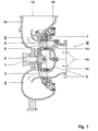
- FIG. 1 is from an exhaust gas turbocharger, only the turbine part with an exhaust gas turbine shown.
- Exhaust gas turbine has a rotatable about an axis 1 rotor 2 with a turbine runner and attached rotor blades 3 and a turbine housing 4 and a nozzle 5 with an axially symmetrical to the turbine axis 1 arranged ring of adjustable Guide vanes 6 and with a pivoting device 7.
- the vanes 6 can each through Turning about a guided in the radial direction axis 8 in any angular positions between two end positions are pivoted.
- the rotor 2 is in gas-tight manner from the turbine housing 4 to a not shown Led bearing point and carries at its left in Fig. 1 end one of the figure 1 no longer visible compressor wheel.
- the turbine housing 4 contains a gas inlet housing 9 with an axisymmetric arranged inlet opening 10 and a gas outlet housing 12 with a radial aligned outlet opening 13. Between inlet opening 10 and outlet opening 13th extends a limited by the turbine housing 4 flow channel 14.
- Inlet opening 10 is symbolized by arrows hot exhaust gas 15 from a not shown exhaust gas source, in particular an internal combustion engine supplied.
- This hot Exhaust gas 15 is first in a direction aligned in the direction of the turbine axis 1 section the flow channel 14 out. In this section, the exhaust gas 15 via the Guides 6 and the blades 3 out. Downstream of the blades 3 occurs that Exhaust gas 15 in a limited by the gas outlet housing 12 section of the Flow channel 14 in which it led away from the axis 1 to the outside and over Finally, the outlet opening 13 is removed from the turbine housing 4.
- the nozzle 5 is at a between the gas inlet 9 and the gas outlet housing 12 by means of screws clamped support ring 16 is held. Between the two housings 9 and 12 is also a clamped by the support ring 16 thermally decoupled relief ring 17, which the Flow channel 14 in the region of the vanes 6 radially outwardly limited and thereby shields the support ring 16 against the direct effect of the hot exhaust gases and thus thermally relieved.
- An attached to each of the vanes 6 blade shank 18 is through acting as a housing wall rings 17 and 16 radially outwardly of the Flow channel 14 out.
- the blade shank 18 is with its outwardly guided part rotatably supported about the pivot axis 8.
- the rotary motion is initiated by a arranged outside the flow channel 14 and rotatable about the turbine axis 1 Adjusting ring 19 and a torque from the adjusting ring 19 on the blade shank 18 each Guide vane transmitting control lever 20.
- the blade shank 18 is attached to the guide blade 6 in such a way that the Swivel axis 8 between the front edge 21 and one of the blade pressure points connecting line 22 of the vane runs. This ensures that the Exhaust gas flow, the guide vane 6 always loaded with a defined torque, thereby undesirable fluttering and swinging of the vane during operation of the vane Exhaust gas turbine can be largely suppressed.
- the outwardly guided part of the blade shaft 18 is at two radially against each other staggered locations 23, 24 stored.
- the two bearings 23, 24 are in the as Section of the housing 4 used support ring 16 is arranged. As between support ring 16 and flow channel 14 of the relief ring 17 is located, the support ring 16 in the radial Direction are large without being concerned that he is undesirably high is exposed to thermal stresses.
- the two bearings 23 and 24 can therefore in be arranged relatively far apart radial direction, whereby of the Lagerstellen23, 24 large bearing forces are kept away.
- the adjusting lever 20 is at its one end by plugging with the blade shank 18th connected.
- the end of the Schaufelschaft 18 two arranged on the type of forks claws, which on two plane-parallel guided holding surfaces of the blade shank 18 are attached.
- the Holding surfaces are arranged between the two bearing points 23, 24. It can be on this Way in the radial direction space can be saved.
- the Adjusting lever 20 is guided in a groove 25 of the adjusting ring 19. This groove 25 is limited by two in essentially radially guided groove walls, which seen in the circumferential direction of the adjusting ring 19 have a distance from each other, which is slightly larger than the diameter of the actuating lever 20.
- the depth of the groove 25 is dimensioned slightly larger than the diameter of the Stellhebels 20. By this dimensioning of the groove 25 is a jam-free leadership of Adjusting lever 20 when executing a caused by turning the adjusting ring 19 Pivoting movement about the pivot axis 8 ensured. By a on the lever 20 attached and supported on the collar 19 spacers 26 ensures that the connector between the lever 20 and blade shank 18 in the execution of Pivoting movement is not affected.
- FIG 3 is a lever 20 of another embodiment of the nozzle 5 after Invention shown. Also, this lever is attached to the blade shank 18. in the Difference to the previously described lever 20 is at this lever 20, however, a fastened from a sheet steel, sheet-shaped fuse element 33 is attached.
- This Securing element 33 has an elastically deformable fork-shaped end 34 on.
- the fork 34 is first spread and engages after completion of the Aufsteckvorganges the blade shank 18 to form a spreading.
- To the Adjusting lever 20 to keep as free of play in the radial direction are in the cylindrical executed blade shank 18 only in the region of the connector with the lever 20 two of Figure 3 apparent plan guided side surfaces molded.
- the Moment transmission from the adjusting ring 19 on the blade shank is characterized by a particularly high level of security, since in contrast to the spacer 26 the Securing element 33 during operation of the diffuser only with relatively small Strain deformation forces is charged.
- the adjusting ring 19 is mounted with its outer surface on Wälzkörpem. As in particular from 4, it can be seen that these rolling elements are pivotally mounted on the support ring 16 one-armed lever 27 executed. At the end remote from the support ring 16 end of each lever 27th a gate is provided into which a guide ring 19 attached to the guide cam 28 engages. Further, in this end of the lever and a recording of a portion of the adjusting ring 19 serving guide groove 29 formed with a on the outer surface of the adjusting ring 19th resting, opposite to the outer surface curved and serving as Wälz Structure Groove base.
- a channel 31 is formed in the support ring 16, a channel 31 is formed.
- This channel can after removal of a cap 32 ( Figure 4) with a coolant source, such as Output of a charge air cooler to be connected.
- the channel 31 is over the Housing passages for the blade shafts 18 guided in the flow channel 14. in the Channel-guided compressed air ensures effective cooling of the nozzle 5 and prevents by overflow into the flow channel 14, the entry of hot exhaust gases in the Diffuser.
Landscapes
- Engineering & Computer Science (AREA)
- Mechanical Engineering (AREA)
- General Engineering & Computer Science (AREA)
- Control Of Turbines (AREA)
- Supercharger (AREA)
Description
- Fig.1
- eine Aufsicht auf einen längs der Turbinenachse geführten Schnitt durch den Turbinenteil eines Abgasturboladers mit einer ersten Ausführungsform des Leitapparats nach der Erfindung,
- Fig.2
- einen vergrössert dargestellten Ausschnitt aus Fig.1,
- Fig.3
- eine Draufsicht auf einen Stellhebel einer zweiten Ausführungsform des Leitapparates nach der Erfindung, und
- Fig.4
- eine Draufsicht in Richtung eines Pfeils IV auf das Gaseintrittsgehäuse und den Leitapparat des Turbinenteils gemäss Fig.1 in perspektivischer Darstellung.
- 1
- Turbinenachse
- 2
- Rotor
- 3
- Laufschaufeln
- 4
- Turbinengehäuse
- 5
- Leitapparat
- 6
- Leitschaufel
- 7
- Schwenkvorrichtung
- 8
- Schwenkachse
- 9
- Gaseintrittsgehäuse
- 10
- Eintrittsöffnung
- 12
- Gasaustrittsgehäuse
- 13
- Austrittsöffnung
- 14
- Strömungskanal
- 15
- Abgasströmung
- 16
- Tragring
- 17
- Entlastungsring
- 18
- Schaufelschaft
- 19
- Stellring
- 20
- Stellhebel
- 21
- Vorderkante
- 22
- Linie der Druckpunkte
- 23, 24
- Lagerstellen
- 25
- Nut
- 26
- Abstandshalter
- 27
- Hebel
- 28
- Führungsnocke
- 29
- Führungsnut
- 30
- Hebel
- 31
- Kühlkanal
- 32
- Verschlusskappe
- 33
- Sicherungselement
- 34
- gabelförmiges Ende
- 35
- Kugelkopf
- 36
- Kugelfläche
Claims (10)
- Leitapparat (5) für eine axial angeströmte Abgasturbine, insbesondere eines Turboladers, mita) axialsymmetrisch zur Turbinenachse (1) in einem Strömungskanal (14) angeordneten Leitschaufeln (6), von denen jede einen durch eine Gehäusewand radial nach aussen aus dem Strömungskanal (14) herausgeführten Schaufelschaft (18) aufweist,b) mit einer Schwenkvorrichtung (7), mit deren Hilfe die Leitschaufeln (6) um eine durch den Schaufelschaft (18) definierte Schwenkachse (8) drehbar sind, wobeic) die Schwenkvorrichtung (7) einen ausserhalb des Strömungskanals (14) auf Wälzkörpern gelagerten und um die Turbinenachse (1) drehbaren Stellring (19)d) sowie einen ein Drehmoment vom Stellring (19) auf den Schaufelschaft (18) jeder Leitschaufel (6) übertragenden Stellhebel (20) aufweist., dadurch gekennzeichnet, dasse) die Wälzkörper jeweils als einarmige Hebel (27) ausgeführt sind, die an einem als Tragring (16) ausgebildeten Bauteil einer Gehäusewand schwenkbar gelagert sind.
- Leitapparat nach Anspruch 1, dadurch gekennzeichnet, dass im vom Tragring (16) abgewandten Ende jedes Hebels (27) jeweils eine am Stellring (19) befestigte Führungsnocke (28) eingreift und eine der Aufnahme eines Abschnitts des Stellrings (19) dienende Führungsnut (29) mit einem auf der Aussenfläche des Stellrings aufliegenden, gegenläufig zur Aussenfläche gekrümmten und als Wälzfläche dienendem Nutgrund eingeformt ist.
- Leitapparat nach Anspruch 1 oder 2, dadurch gekennzeichnet, dass der nach aussen geführte Teil des Schaufelschafts (18) auf zwei radial gegeneinander versetzt angeordneten Stellen (23, 24) im Tragring (16) gelagert ist.
- Leitapparat nach einem der Ansprüche 1 bis 3, dadurch gekennzeichnet, dass der Tragring (16) durch einen den Strömungskanal (14) nach aussen begrenzenden Entlastungsring (17) thermisch entlastet ist.
- Leitapparat nach einem der Ansprüche 1 bis 4, dadurch gekennzeichnet, dass der Stellhebel (20) zwischen den beiden Lagerstellen (23, 24) mit dem Schaufelschaft (18) verbunden ist.
- Leitapparat nach einem der Ansprüche 1 bis 5, dadurch gekennzeichnet, dass der Stellhebel (20) lösbar mit dem Schaufelschaft (18) verbunden und mittels einer Spielsicherung gegen Spiel zwischen Schaufelschaft und Stellhebel gesichert ist.
- Leitapparat nach Anspruch 6, dadurch gekennzeichnet, dass der Stellhebel (20) auf den Schaufelschaft (18) aufgesteckt ist, und die Spielsicherung ein auf dem Stellring (19) abgestützter Abstandshalter (26) ist.
- Leitapparat nach Anspruch 6, dadurch gekennzeichnet, dass der Stellhebel (20) auf den Schaufelschaft (18) aufgesteckt ist, und die Spielsicherung ein den Schaufelschaft (18) hintergreifendes Sicherungselement (33) ist.
- Leitapparat nach einem der Ansprüche 1 bis 8, dadurch gekennzeichnet, dass in den Tragring (16) ein mit einer Kühlmittelquelle verbindbarer Kühlkanal (31) eingeformt ist, welcher über die Gehäusedurchführungen der Schaufelschäfte (18) in den Strömungskanal (14) geführt ist.
- Leitapparat nach einem Ansprüche 1 bis 9, dadurch gekennzeichnet, dass der Schaufelschaft (18) derart mit der Leitschaufel (6) verbunden ist, dass die Schwenkachse (18) zwischen der Vorderkante (21) und einer Schaufeldruckpunkte verbindenden Linie (22) der Leitschaufel (6) verläuft.
Applications Claiming Priority (3)
| Application Number | Priority Date | Filing Date | Title |
|---|---|---|---|
| DE10013335A DE10013335A1 (de) | 2000-03-17 | 2000-03-17 | Leitapparat für eine axial durchströmte Abgasturbine |
| DE10013335 | 2000-03-17 | ||
| PCT/CH2001/000139 WO2001069044A1 (de) | 2000-03-17 | 2001-03-06 | Leitapparat für eine axial durchströmte abgasturbine |
Publications (2)
| Publication Number | Publication Date |
|---|---|
| EP1264079A1 EP1264079A1 (de) | 2002-12-11 |
| EP1264079B1 true EP1264079B1 (de) | 2005-01-05 |
Family
ID=7635318
Family Applications (1)
| Application Number | Title | Priority Date | Filing Date |
|---|---|---|---|
| EP01907304A Expired - Lifetime EP1264079B1 (de) | 2000-03-17 | 2001-03-06 | Leitapparat für eine axial durchströmte abgasturbine |
Country Status (10)
| Country | Link |
|---|---|
| US (1) | US6824355B2 (de) |
| EP (1) | EP1264079B1 (de) |
| JP (1) | JP4526055B2 (de) |
| KR (1) | KR100751743B1 (de) |
| CN (1) | CN1304733C (de) |
| AU (1) | AU2001235307A1 (de) |
| CZ (1) | CZ298199B6 (de) |
| DE (2) | DE10013335A1 (de) |
| TW (1) | TW513516B (de) |
| WO (1) | WO2001069044A1 (de) |
Families Citing this family (33)
| Publication number | Priority date | Publication date | Assignee | Title |
|---|---|---|---|---|
| DE10311227B4 (de) * | 2003-03-14 | 2005-03-31 | Man B & W Diesel Ag | Leitapparat |
| EP1604280B1 (de) * | 2003-03-19 | 2012-07-04 | BRITISH TELECOMMUNICATIONS public limited company | Flexible mehragent-systemarchitektur |
| GB2402180B (en) * | 2003-05-30 | 2006-09-20 | Rolls Royce Plc | Variable stator vane actuating levers |
| DE102004038748A1 (de) * | 2004-08-10 | 2006-02-23 | Daimlerchrysler Ag | Abgasturbolader für eine Brennkraftmaschine |
| EP1669548A1 (de) * | 2004-12-08 | 2006-06-14 | ABB Turbo Systems AG | Leitapparat für Abgasturbine |
| DE102005027890B4 (de) * | 2005-06-16 | 2007-05-03 | Man Diesel Se | Abgasturbolader für eine Brennkraftmaschine |
| DE102007021448B4 (de) * | 2006-05-18 | 2012-06-28 | Man Diesel & Turbo Se | Leitapparat für einen Abgasturbolader einer mit Schweröl betriebenen Hubkolben-Brennkraftmaschine |
| CH700499B1 (de) * | 2006-05-18 | 2010-09-15 | Man Diesel & Turbo Se | Leitapparat für eine Turbine eines Abgasturboladers sowie Abgasturbolader mit demselben. |
| CH698928B1 (de) * | 2006-05-18 | 2009-12-15 | Man Diesel Se | Leitapparat für eine axial angeströmte Turbine eines Abgasturboladers. |
| DE102007021340B4 (de) * | 2006-05-18 | 2021-06-02 | Man Energy Solutions Se | Leitapparat für einen Abgasturbolader einer mit Schweröl betriebenen Hubkolben-Brennkraftmaschine |
| DE102006039064B4 (de) * | 2006-08-19 | 2020-06-25 | Man Energy Solutions Se | Abgasturbolader für eine Brennkraftmaschine |
| EP2092165B1 (de) | 2006-12-20 | 2010-10-20 | ABB Technology AG | Verwendung eines turboladers und abwärmeumwandlungssystem |
| WO2008116922A2 (de) * | 2007-03-27 | 2008-10-02 | Abb Turbo Systems Ag | Gehäuseisolation |
| EP2080871A1 (de) * | 2008-01-15 | 2009-07-22 | ABB Turbo Systems AG | Leitvorrichtung für Schaufelverstellung |
| US20110138805A1 (en) * | 2009-12-15 | 2011-06-16 | Honeywell International Inc. | Conjugate curve profiles for vane arms, main-arms, and unison rings |
| US8468826B2 (en) * | 2010-04-19 | 2013-06-25 | Honeywell International Inc. | Axial turbine wheel |
| US20110173972A1 (en) * | 2010-06-14 | 2011-07-21 | Robert Andrew Wade | Internal Combustion Engine Cylinder Head With Integral Exhaust Ducting And Turbocharger Housing |
| US9874218B2 (en) * | 2011-07-22 | 2018-01-23 | Hamilton Sundstrand Corporation | Minimal-acoustic-impact inlet cooling flow |
| DE102011119879A1 (de) * | 2011-12-01 | 2013-06-06 | Ihi Charging Systems International Gmbh | Fluidenergiemaschine, insbesondere für einen Abgasturbolader eines Kraftwagens |
| WO2013116136A1 (en) * | 2012-02-02 | 2013-08-08 | Borgwarner Inc. | Mixed-flow turbocharger with variable turbine geometry |
| DE102015223257A1 (de) * | 2015-11-25 | 2017-06-01 | Volkswagen Aktiengesellschaft | Abgasturbine, Abgasturbolader, Brennkraftmaschine und Kraftfahrzeug |
| CN105464711A (zh) * | 2015-12-14 | 2016-04-06 | 中国北方发动机研究所(天津) | 一种适合脉冲增压的新型轴流涡轮机 |
| DE102016110269A1 (de) * | 2016-06-03 | 2017-12-07 | Man Diesel & Turbo Se | Axialturbine eines Turboladers und Turbolader |
| DE102016114253A1 (de) * | 2016-08-02 | 2018-02-08 | Man Diesel & Turbo Se | Axialturbine eines Turboladers und Turbolader |
| CN106437870B (zh) * | 2016-08-31 | 2018-09-11 | 中车大连机车研究所有限公司 | 轴流涡轮增压器可调喷嘴装置 |
| US10767564B2 (en) | 2017-03-17 | 2020-09-08 | Hamilton Sunstrand Corporation | Air turbine starter with automated variable inlet vanes |
| DE102017114608A1 (de) * | 2017-06-30 | 2019-01-03 | Man Diesel & Turbo Se | Turbinenzuströmgehäuse einer Axialturbine eines Turboladers |
| JP6939682B2 (ja) * | 2018-04-06 | 2021-09-22 | トヨタ自動車株式会社 | 内燃機関 |
| WO2019217979A1 (en) | 2018-05-09 | 2019-11-14 | Gaffoor Feizal Alli | Turbocharger |
| CN112096658B (zh) * | 2020-11-06 | 2021-01-22 | 中国航发上海商用航空发动机制造有限责任公司 | 航空发动机压气机及其可调静子叶片位置保持结构 |
| DE102021129534A1 (de) * | 2021-11-12 | 2023-05-17 | MTU Aero Engines AG | Leitschaufelanordnung einer Strömungsmaschine und Verfahren zur Montage einer Leitschaufelanordnung |
| CN116950725A (zh) * | 2023-08-11 | 2023-10-27 | 中国航发燃气轮机有限公司 | 一种联动环定心结构及其燃气轮机 |
| EP4571056A1 (de) * | 2023-12-13 | 2025-06-18 | MTU Aero Engines AG | Schaufelverstellarm für eine gasturbine, strömungsmaschine mit dem schaufelverstellarm und verfahren zur montage eines schaufelverstellarms für eine strömungsmaschine |
Family Cites Families (17)
| Publication number | Priority date | Publication date | Assignee | Title |
|---|---|---|---|---|
| BE496713A (de) * | 1949-07-01 | |||
| DE1121885B (de) | 1960-06-14 | 1962-01-11 | Daimler Benz Ag | Leitschaufel-Verstellvorrichtung fuer Stroemungsmaschinen, insbesondere Gasturbinen |
| US4066694A (en) * | 1971-02-09 | 1978-01-03 | Pfizer Inc. | 4-hydroxy-4-dedimethylamino-tetracyclines |
| GB1410481A (en) | 1972-01-12 | 1975-10-15 | Lucas Industries Ltd | Control vane arrangement for a turbine |
| CH558477A (de) * | 1972-11-27 | 1975-01-31 | Bbc Sulzer Turbomaschinen | Verstellvorrichtung fuer drehbare leitschaufeln. |
| US4003675A (en) * | 1975-09-02 | 1977-01-18 | Caterpillar Tractor Co. | Actuating mechanism for gas turbine engine nozzles |
| JPS597708A (ja) * | 1982-07-07 | 1984-01-14 | Hitachi Ltd | 軸流機械における静翼取付角可変装置 |
| DE3325756C1 (de) | 1983-07-16 | 1984-09-13 | Aktiengesellschaft Kühnle, Kopp & Kausch, 6710 Frankenthal | Verstellbarer Leitapparat |
| JPH0352987Y2 (de) * | 1984-10-04 | 1991-11-19 | ||
| JPS61128342U (de) * | 1985-01-31 | 1986-08-12 | ||
| DE3516685C2 (de) * | 1985-05-09 | 1987-04-16 | Daimler-Benz Ag, 7000 Stuttgart | Vorrichtung zur Kühlung eines zur Lagerung des Verstellringes einer Luftschaufelverstelleinrichtung für die Nutzleistungsturbine eines Gasturbinentriebwerks vorgesehenen Drahtlagers |
| DE3623001C1 (de) * | 1986-07-09 | 1987-07-09 | Mtu Muenchen Gmbh | Verstellvorrichtung fuer schwenkbare Leitschaufeln von Turbotriebwerken |
| JPS6369736U (de) * | 1986-10-27 | 1988-05-11 | ||
| US4979874A (en) * | 1989-06-19 | 1990-12-25 | United Technologies Corporation | Variable van drive mechanism |
| DE4100224C2 (de) * | 1991-01-07 | 1994-05-19 | Daimler Benz Ag | Halterung eines Diffusors einer Gasturbine in einem Turbinengehäuse |
| US5553117A (en) * | 1994-01-03 | 1996-09-03 | Danny R. Peterson | Vehicular communications system |
| DE19640872C2 (de) | 1996-10-04 | 1999-07-01 | Ind Fahrzeugtechnik Gmbh & Co | Nocken für gebaute Nockenwelle |
-
2000
- 2000-03-17 DE DE10013335A patent/DE10013335A1/de not_active Withdrawn
-
2001
- 2001-03-06 WO PCT/CH2001/000139 patent/WO2001069044A1/de not_active Ceased
- 2001-03-06 AU AU2001235307A patent/AU2001235307A1/en not_active Abandoned
- 2001-03-06 CZ CZ20023107A patent/CZ298199B6/cs not_active IP Right Cessation
- 2001-03-06 EP EP01907304A patent/EP1264079B1/de not_active Expired - Lifetime
- 2001-03-06 CN CNB018096476A patent/CN1304733C/zh not_active Expired - Lifetime
- 2001-03-06 KR KR1020027012037A patent/KR100751743B1/ko not_active Expired - Fee Related
- 2001-03-06 DE DE50105028T patent/DE50105028D1/de not_active Expired - Lifetime
- 2001-03-06 JP JP2001567904A patent/JP4526055B2/ja not_active Expired - Fee Related
- 2001-03-06 US US10/221,661 patent/US6824355B2/en not_active Expired - Lifetime
- 2001-03-09 TW TW090105541A patent/TW513516B/zh not_active IP Right Cessation
Also Published As
| Publication number | Publication date |
|---|---|
| TW513516B (en) | 2002-12-11 |
| DE50105028D1 (de) | 2005-02-10 |
| KR100751743B1 (ko) | 2007-08-27 |
| US20030049120A1 (en) | 2003-03-13 |
| WO2001069044A1 (de) | 2001-09-20 |
| KR20020077535A (ko) | 2002-10-11 |
| CN1429311A (zh) | 2003-07-09 |
| EP1264079A1 (de) | 2002-12-11 |
| CN1304733C (zh) | 2007-03-14 |
| JP2003527521A (ja) | 2003-09-16 |
| AU2001235307A1 (en) | 2001-09-24 |
| JP4526055B2 (ja) | 2010-08-18 |
| DE10013335A1 (de) | 2001-09-20 |
| CZ20023107A3 (en) | 2004-03-17 |
| US6824355B2 (en) | 2004-11-30 |
| CZ298199B6 (cs) | 2007-07-18 |
Similar Documents
| Publication | Publication Date | Title |
|---|---|---|
| EP1264079B1 (de) | Leitapparat für eine axial durchströmte abgasturbine | |
| EP2002127B1 (de) | Vordrall-leitvorrichtung | |
| EP1662094B1 (de) | Leitapparat für einen Abgasturbolader sowie Abgasturbolader | |
| DE60112822T2 (de) | Turbine mit veränderlicher Kapazität | |
| EP0224083B1 (de) | Abgasturbolader | |
| EP0289697B1 (de) | Verstelleinrichtung für die Leitschaufeln einer Axialströmungsmaschine | |
| DE3874439T2 (de) | Kompressor mit geteiltem gehaeuse. | |
| EP0093462B1 (de) | Abgasturbolader mit verstellbarem Ringschieber | |
| DE2810240C2 (de) | Verstelleitgitter für axial durchströmte Turbinen, insbesondere Hochdruckturbinen von Gasturbinentriebwerken | |
| EP1495210B1 (de) | Turbolader mit mittel auf der welle zur axialen sicherung der besagten welle beim bersten des verdichterrades | |
| DE69818589T2 (de) | Positionierantriebsvorrichtung mit Spieleinstellung für variablen rohrförmigen Diffusor | |
| EP1977085A1 (de) | Verstellbare leitvorrichtung | |
| DE112017001114B4 (de) | Düsenantriebsmechanismus, Turbolader und Turbolader mit variabler Kapazität | |
| EP2455584A1 (de) | Gasturbine mit Steuerungsmittel zur Kühlung, welche teilweise aus einer Gedächtnislegierung bestehen | |
| EP1520959B1 (de) | Turbokompressor mit verstellbaren Leitschaufeln | |
| EP1734231B1 (de) | Turbolader mit variabler turbinengeometrie | |
| WO2006060925A1 (de) | Leitapparat für abgasturbine | |
| DE10011440B4 (de) | Abgasturbolader mit verstellbaren Düsenflügeln | |
| EP2243932B1 (de) | Abgasturboladerturbine mit einem eine Reihe von verstellbaren Leitschaufeln umfassenden Leitapparat | |
| DE10011441A1 (de) | Gasdichtungsvorrichtung für einen Auflader mit variabler Leistung | |
| DE102011103518A1 (de) | Abblaseventil | |
| WO2018162306A1 (de) | Turbine mit verstellbaren leitschaufeln | |
| DE602004006197T2 (de) | Führungszusammenbau für aussenliegendes Lager einer verstellbaren Schaufel einer Turbomaschine | |
| EP1574673B1 (de) | Leitgitter variabler Geometrie und Turbolader mit einem solchen Leitgitter | |
| EP1391585B1 (de) | Turbolader mit variabler Turbinengeometrie |
Legal Events
| Date | Code | Title | Description |
|---|---|---|---|
| PUAI | Public reference made under article 153(3) epc to a published international application that has entered the european phase |
Free format text: ORIGINAL CODE: 0009012 |
|
| 17P | Request for examination filed |
Effective date: 20020909 |
|
| AK | Designated contracting states |
Kind code of ref document: A1 Designated state(s): AT BE CH CY DE DK ES FI FR GB GR IE IT LI LU MC NL PT SE TR |
|
| AX | Request for extension of the european patent |
Free format text: AL;LT;LV;MK;RO;SI |
|
| RBV | Designated contracting states (corrected) |
Designated state(s): DE FR GB |
|
| GRAP | Despatch of communication of intention to grant a patent |
Free format text: ORIGINAL CODE: EPIDOSNIGR1 |
|
| RAP1 | Party data changed (applicant data changed or rights of an application transferred) |
Owner name: ABB TURBO SYSTEMS AG |
|
| GRAS | Grant fee paid |
Free format text: ORIGINAL CODE: EPIDOSNIGR3 |
|
| GRAA | (expected) grant |
Free format text: ORIGINAL CODE: 0009210 |
|
| AK | Designated contracting states |
Kind code of ref document: B1 Designated state(s): DE FR GB |
|
| REG | Reference to a national code |
Ref country code: GB Ref legal event code: FG4D Free format text: NOT ENGLISH |
|
| REG | Reference to a national code |
Ref country code: IE Ref legal event code: FG4D Free format text: GERMAN |
|
| REF | Corresponds to: |
Ref document number: 50105028 Country of ref document: DE Date of ref document: 20050210 Kind code of ref document: P |
|
| GBT | Gb: translation of ep patent filed (gb section 77(6)(a)/1977) |
Effective date: 20050406 |
|
| PLBE | No opposition filed within time limit |
Free format text: ORIGINAL CODE: 0009261 |
|
| STAA | Information on the status of an ep patent application or granted ep patent |
Free format text: STATUS: NO OPPOSITION FILED WITHIN TIME LIMIT |
|
| ET | Fr: translation filed | ||
| 26N | No opposition filed |
Effective date: 20051006 |
|
| REG | Reference to a national code |
Ref country code: GB Ref legal event code: FG4D Free format text: NOT ENGLISH |
|
| REG | Reference to a national code |
Ref country code: FR Ref legal event code: PLFP Year of fee payment: 16 |
|
| REG | Reference to a national code |
Ref country code: FR Ref legal event code: PLFP Year of fee payment: 17 |
|
| REG | Reference to a national code |
Ref country code: FR Ref legal event code: PLFP Year of fee payment: 18 |
|
| PGFP | Annual fee paid to national office [announced via postgrant information from national office to epo] |
Ref country code: DE Payment date: 20180322 Year of fee payment: 18 Ref country code: GB Payment date: 20180321 Year of fee payment: 18 |
|
| PGFP | Annual fee paid to national office [announced via postgrant information from national office to epo] |
Ref country code: FR Payment date: 20180323 Year of fee payment: 18 |
|
| REG | Reference to a national code |
Ref country code: DE Ref legal event code: R119 Ref document number: 50105028 Country of ref document: DE |
|
| GBPC | Gb: european patent ceased through non-payment of renewal fee |
Effective date: 20190306 |
|
| PG25 | Lapsed in a contracting state [announced via postgrant information from national office to epo] |
Ref country code: GB Free format text: LAPSE BECAUSE OF NON-PAYMENT OF DUE FEES Effective date: 20190306 Ref country code: DE Free format text: LAPSE BECAUSE OF NON-PAYMENT OF DUE FEES Effective date: 20191001 |
|
| PG25 | Lapsed in a contracting state [announced via postgrant information from national office to epo] |
Ref country code: FR Free format text: LAPSE BECAUSE OF NON-PAYMENT OF DUE FEES Effective date: 20190331 |