EP1264291B1 - Mikrosystem mit einem magnetometrischen sensor und einem neigungssensor zur überwachung von wertsachen - Google Patents
Mikrosystem mit einem magnetometrischen sensor und einem neigungssensor zur überwachung von wertsachen Download PDFInfo
- Publication number
- EP1264291B1 EP1264291B1 EP01913992A EP01913992A EP1264291B1 EP 1264291 B1 EP1264291 B1 EP 1264291B1 EP 01913992 A EP01913992 A EP 01913992A EP 01913992 A EP01913992 A EP 01913992A EP 1264291 B1 EP1264291 B1 EP 1264291B1
- Authority
- EP
- European Patent Office
- Prior art keywords
- alert
- message
- processing
- magnetometer
- triggering
- Prior art date
- Legal status (The legal status is an assumption and is not a legal conclusion. Google has not performed a legal analysis and makes no representation as to the accuracy of the status listed.)
- Expired - Lifetime
Links
Images

Classifications
-
- G—PHYSICS
- G08—SIGNALLING
- G08B—SIGNALLING SYSTEMS, e.g. PERSONAL CALLING SYSTEMS; ORDER TELEGRAPHS; ALARM SYSTEMS
- G08B13/00—Burglar, theft or intruder alarms
- G08B13/02—Mechanical actuation
- G08B13/14—Mechanical actuation by lifting or attempted removal of hand-portable articles
- G08B13/1436—Mechanical actuation by lifting or attempted removal of hand-portable articles with motion detection
Definitions
- the invention lies in the field of alarm triggering assemblies when it is detected that a normally immobile object, for example an art object exhibited in a museum, moves abnormally. It also relates to a method of assisting the monitoring of a set of objects and an object or set of objects equipped with means for detecting movement and sending messages.
- the patent application RU 2104 554 thus describes a measurement system for determining the pitch and yaw roll speeds of a vehicle.
- the device uses variations in the value of the local terrestrial magnetic field on each of three vehicle-related axes. From these measurements, it is possible to determine the value of pitch and yaw roll speeds of the vehicle. By subtraction of the global rotation speed vector, the global motion vector gives the linear velocity of the vehicle.
- the device relates to a property protection assembly 2a, 2b, 2c which may be, for example, a television set, a calculator, a radio or works of art.
- a property protection assembly 2a, 2b, 2c which may be, for example, a television set, a calculator, a radio or works of art.
- Each of the devices comprises a motion detection assembly 3a, 3b or 3c.
- a message is transmitted by one of the devices 3 to an alarm center 1 which triggers an alarm 12.
- each of the devices 3 comprises a motion detector 9 whose signal is processed by a microprocessor 5 to possibly trigger an alarm through means 4 or a transmitter 7.
- An interface 10 makes it possible to activate or deactivate each of the sets 3. It is indicated in column 3, line 41 that the motion detection means 9 may comprise a ball device.
- a ball 4 is movable inside a coil 3 coiled on a coil body 2.
- Contact terminals 7, 8 can pick up a voltage across the coil 3.
- a processing system consisting of an amplifier 9, a counter 10 or a counter 12 and an alarm trigger 11 can trigger an alarm in case of movement of the object on which the detector is placed or in case of magnetic change due to a displacement of this object.
- the operation is as follows; the ball 4 is made of mild steel and its movements induce changes in the value of the voltage at the terminals 7, 8 of the coil.
- These voltages are amplified by the amplifier 9, the voltage pulses are counted in a counter 10 and the alarm is triggered when a predetermined number of pulses or vibrations is counted.
- the counter 12 makes it possible to count voltage variations due to a distance or a change in the magnetic medium in which the detection assembly is immersed.
- a removal of a magnetic mass or an approximation of such a mass causes variations in the voltage at the terminals 7, 8 which, if they are proved by the counter 12, can trigger the alarm 11.
- These surveillance systems may also include, for example, video sets monitoring by camera the works to be protected. These systems require the presence of an operator to carefully monitor the image or images from each of the cameras. It has also been envisaged magnetic marking systems in which a magnetic resonator is included in the the work to watch. The passage of the work containing the resonator through a gantry receiving a frequency corresponding to the resonance frequency of the resonator can detect the passage of the work. Such devices assume that the protected work will go through the portico. Implantable microchips, infrared curtains, mercury ball contactors, piezoelectric devices, accelerometers have also been envisaged. These systems could be satisfactory if the false alarm rate was not as important.
- the present invention is a new device for detecting a movement of the protected object, with a very low rate of false alarm.
- the present invention relates to a device for detecting an abnormal movement, that is to say different from the "invisible" movements of an object considered immobile, a protected work. It aims a device generating a false alarm rate very low or zero. It aims at a device aimed at limiting the quantity and the vigilance of the surveillance personnel. It aims at a device aimed at limiting the quantity and the vigilance of the surveillance personnel. It also aims to detect a theft or attempted theft from the beginning of the offense.
- the invention relates to a set of triggering an alert or a pre-alert, as defined by claim 1.
- the signals emitted by the magnetometer (s) and possibly other sensor means such as an inclinometer are digital.
- the filtering can be performed in the form of Kalman filtering to reduce the convergence time of the processing algorithm and to determine a moving average value taking into account the temporal evolution of the received values.
- the detection means further comprise one or more inclinometers with one or more axes mechanically secured to the object to be protected and coupled to the processing means.
- the device further comprises one or more additional magnetometers mechanically secured to the object, connected to the processing means.
- the device may comprise a generator of a magnetic field, for example, random. This generator is coupled to the processing means so that they are able to permanently determine the parameters defining a local magnetic field vector.
- the distribution of the means constituting the alarm trigger assembly may vary.
- the means attached to the object may comprise the measurement means, the measurement transmission means, the processing means and the message transmission means.
- the means for transmitting the measured values to the means for processing the measured values may consist of a single connection, for example a wired connection.
- the warning triggering means of the station monitoring are coupled to the processing means via the message transmitting means and message receiving means.
- the means attached to the object comprise only the measuring means and the means for transmitting the measured values.
- the means for transmitting the measurements include the message transmission means.
- the alert tripping means are coupled to the processing means by a single connection for example wire.
- the invention also relates to a method of monitoring an object or set of objects as defined by claim 10.
- the real movement of the object can be much more complex than a simple rotation, it can then be interesting, to reduce the rate of error, to detect a succession of rotations that constitute this movement.
- the magnitudes to be compared will then be calculated from a multicomponent vector quantity.
- the presence message is constituted by the message transmitting the measurement values of the measuring means.
- the presence and alert messages are transmitted in the form of a free electromagnetic wave.
- the transmission of the alert message is done on a frequency different from the transmission frequency of the presence message.
- the presence and alert messages include an identification code of the monitored object and / or a location of the monitored object.
- the alert transmission means are standard means IR, video etc.
- an alert causes the appearance of at least one reported image of the object on a screen of a monitor of the monitoring station.
- the image is said to be indicated in this way, that the monitor, showing the image, is indicated for example by a blinking of a lamp associated with the monitor or by an audible signal.
- the station can count means measuring a rotational movement of the object, these means being mechanically integral with the object, for example one or more one or more axis magnetometers, optionally associated with one or more inclinometers one or more axes, means for transmission of presence message and warning message, these means being coupled to processing means coupled to the means for measuring a rotation of the object.
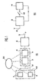
- a device comprises, on the one hand, means 10 fixed to the object together constituting a detection station of the object to be protected and, on the other hand, receiving and triggering means 20 alarm, constituting together at least a portion of a monitoring station, coupled to different objects to be protected.
- the detection means attached to the object comprise, on the one hand, a magnetometer 1 coupled by measurement transmission means 15, for example a wire link, to processing means 5, these processing means being coupled to means transmitting message 6 transmitting via an antenna or other means 7 a message to a monitoring station 20, disposed near or objects to monitor.
- the means attached to the object comprise a power supply source 30 coupled to the constituent elements of these fixed means. This source may be a battery, a microbattery, a cell for transforming an electromagnetic wave into an electric current or any other known means.
- the monitoring station 20 comprises, on the one hand, a message receiving station 9 coupled via a switch 12 to an alarm sending means 11.
- the alarm sending means 11 is coupled in return on the station 9 so as to allow after alert an acknowledgment function, for example, by resetting the alarm trigger.
- the communication means between the detection station 10 and the warning station 20 have been represented in the form of an antenna 7 coupled to the message transmission means 6 of the detection station and an antenna 8 coupled to the receiving means 9 of the monitoring station 20.
- These antennas assume that the connection between the detection station 10 and the warning station 20 is in the form of an electromagnetic link.
- This mode of embodiment is the preferred mode. It is obvious, however, that the connection between the receiving station 20 and detection and transmission 10 can be performed by any other means of connection known in particular, a wired link or an infrared link.
- the signal processing means 5 comprise, on the one hand, means 3 for processing the signal of the magnetometer 1 and, on the other hand, means 4 for filtering this signal and for detecting the movement.
- the means 3 receive the data coming from the magnetometer 1 and process these data to form at least one rotation vector, or at least one component of this vector, of the magnetometer 1 with respect to the local magnetic field of the object.
- This rotation vector is then filtered by the filtering means 4, for example, a Kalman filter or from a so-called “maximum likelihood” technique or any algorithm relating to the detection / estimation in information theory, for detect a rotation amplitude greater than a fixed threshold and trigger a message in case the detected rotation has an amplitude greater than the threshold.
- the filtering means 4 for example, a Kalman filter or from a so-called “maximum likelihood” technique or any algorithm relating to the detection / estimation in information theory, for detect a rotation amplitude greater than a fixed threshold and trigger a message in case the detected rotation has an amplitude greater than the threshold.
- the magnetometer one or more axes 1 continuously measures the magnetic field present on each of these axes.
- the value of the magnetic field present on each of the axes is sent continuously to the processing means 3.
- the processing means 3 generate on receipt of each set of values from the magnetometer 1 the value of a rotation vector of the magnetic field captured by each axis of the magnetometer 1 relative to the natural magnetic field or not surrounding the object to be detected.
- the object is in principle immobile, this immobility is not complete.
- the object is subjected to the natural seismic noise of the building of implantation of the object.
- the object is subject to any vibrations due to the activity around the object and around the building where the magnetometer 1 is fixed to the object.
- the natural local magnetic field around the magnetometer 1 may vary in particular due to changes in the magnetic conditions around this magnetometer induced in particular by the passage of visitors.
- Other reasons for mobility of the object and therefore the magnetometer may be due to the nature of the object.
- the table according to its mode of attachment can be sensitive to drafts causing slight local movements of the fabric and possibly the frame of the table.
- weather conditions can induce large transient variations in the local magnetic field, especially in the event of a magnetic storm.
- the rotation vector calculated by the processing means 3 is filtered in filtering and detection means 4. These means make it possible to determine an adaptive average value of the noise of the vector rotation of the magnetometer. This adaptive average value is multiplied by a false alarm safety factor to provide an adaptive threshold. When the value of the rotation vector exceeds the adaptive threshold thus fixed, the filtering and detection means 4 change their logic state which constitutes a message for the message transmission means 6.
- the transmission means 6 emit, of Preferably, permanently a message in the direction of the receiving station 9. When no amplitude rotation greater than the threshold is detected, the message is a presence message. When a rotation greater than the predetermined threshold is detected, an alert message is immediately transmitted.
- the presence and alert messages comprise a set of identification signals of the object on which the device 10 is fixed and / or the location of the object in the monitored enclosure, for example, the Museum.
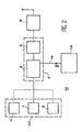
- the device 40 for measuring a rotation further comprises an inclinometer 2 connected to the processing means 3.
- the processing means 3 elaborate the rotation vector of the object taking into account the data coming from on the one hand, the magnetometer and, on the other hand, the inclinometer. This device makes decoying rotation detection even more difficult.
- the device represented in figure 2 comprises one or more additional magnetometers 1 'distributed over the surface of the object to be protected and / or in the immediate vicinity. These magnetometers 1 'are connected to the processing means 3. With this set of magnetometers 1, 1' it is possible to calculate a value and a direction of the magnetic field with respect to a reference trihedron linked to the object to be protected. When this field undergoes rotations or changes in its average time value with respect to this trihedron, this modification is detected by the measuring and treatment and filtering means 5 which, in this case, must be adapted to this function, and an alert message is issued.
- the invention may include a magnetic field generator 13.
- This generator permanently or randomly causes a magnetic field which is intended to facilitate the calculation of a modification of the magnetic field due to the presence of an external metal object.
- the generator 13 also causes a local variation of the magnetic field so that the local magnetic field vector varies in the space in modulus and direction. It thus becomes possible to detect any movement of rotation and / or translation.
- the characteristics of the magnetic field caused by the generator 13 are transmitted by a link 14 to the calculation means 3.
- the processing means 3 and 4 are located on the side of the object. These processing means can also be arranged on the side of the monitoring station as shown figure 3 .
- the measuring means 40 composed of one or more magnetometers 1, 1 'as in the previous case and possibly inclinometers 2 are coupled to a transmitter 6.
- the processing means 3, 4 are These means 3, 4 are directly coupled to the warning trigger 11.
- This version may comprise, like the previous versions, a magnetic field generator 13 which is in this case coupled to the means 3, 4 of the invention. located on the side of the monitoring station.
- This version of the invention operates as the previous one.
- the presence message is this time obligatory. It consists of measurement transmissions. An absence of such a transmission will trigger a particular message of the processing means 3, 4 by triggering alert 11.
- An alert message is a message different from a presence message.
- the alert message further contains a code whose reception at the monitoring station triggers the alert.
- the code can be constituted by a simple change of the transmission frequency.
- the device described in connection with the Figures 1 to 3 has been described as an isolated device inside an enclosure. It is obvious that, especially in a museum, the objects to be protected are not isolated and that there may be several thousand objects to protect in a small volume enclosure. There is therefore a problem of managing the presence and alert messages for all the objects to be protected contained in the enclosure.
- the links between the transmission means 6 and the receiving means 9 are point-to-point links, for example wired or infrared, it is possible to identify the object by the source of the message received on the receiving means.
- the connection between the transmission means 6 and the reception means 9 is electromagnetic, there is a problem of frequency management.
- This problem can be solved, either by frequency allocation to each of the objects, or by time distribution, programmed or random, of the emission slots of each object, or else by a combination of the two methods, that is to say ie allocation of different frequencies and distribution of transmission slots for each of the frequencies.
Landscapes
- Physics & Mathematics (AREA)
- General Physics & Mathematics (AREA)
- Geophysics And Detection Of Objects (AREA)
- Emergency Alarm Devices (AREA)
- Burglar Alarm Systems (AREA)
Claims (10)
- Auslösesystem eines Alarms oder eines Voralarms, wenn bei einem normalerweise immobilen Gegenstand eine Bewegung detektiert wird, wobei dieses System umfasst:- Messeinrichtungen (40), die Messwerte erzeugen,- Übertragungseinrichtungen (5) der gemessenen Werte zu Verarbeitungseinrichtungen (3, 4, 5) der gemessenen Werte,- Meldungs-Sendeeinrichtungen (6),- Überwachungseinrichtungen (20), umfassend:- Meldungs-Empfangseinrichtungen (9),- Alarmauslösungseinrichtungen (11),
bei dem außerdem:- die Messeinrichtungen (40) wenigstens ein fest mit dem Gegenstand verbundenes ein- oder mehrachsiges Magnetometer (1) umfassen, das auf wenigstens einer Achse das Magnetfeld misst,- die Verarbeitungseinrichtungen (3, 4, 5) aufgrund einer Serie von den Messeinrichtungen (40) stammender Messungen eine für eine Bewegung repräsentative Vektorgröße berechnen und ein Bewegungsdetektionssignal erzeugen, wenn die berechnete Vektorgröße einen Vektorschwellenwert überschreitet,- die Alarmauslösungseinrichtungen mit den Messungsverarbeitungseinrichtungen (3, 4, 5) gekoppelt sind und bei Empfang des von den genannten Messungsverarbeitungseinrichtungen (3, 4, 5) stammenden Detektionssignals ein Alarmsignal aussenden. - Auslösesystem eines Alarms nach Anspruch 1, dadurch gekennzeichnet, dass der Vektorschwellenwert eine vorgegebene Größe ist.
- Auslösesystem eines Alarms nach Anspruch 1, dadurch gekennzeichnet, dass der Vektorschwellenwert eine in Abhängigkeit von einem aufgrund der letzten gemessenen Vektorgrößen berechnete variable Größe ist.
- Alarmauslösesystem nach einem der Ansprüche 1 bis 3, dadurch gekennzeichnet, dass die Verarbeitungseinrichtungen (3, 4, 5) von dem Gegenstand beabstandet sind.
- Alarmauslösesystem nach einem der Ansprüche 1 bis 3, dadurch gekennzeichnet, dass die Messungsverarbeitungseinrichtungen (3, 4, 5) sich auf dem Gegenstand befinden.
- Alarmauslösesystem nach Anspruch 5, dadurch gekennzeichnet, dass die fest mit dem Gegenstand verbundenen Messeinrichtungen (40) außerdem einen oder mehrere ein- oder mehrachsige Neigungsmesser (2) umfassen.
- Alarmauslösesystem nach einem der Ansprüche 5 oder 6, dadurch gekennzeichnet, dass die Meldungs-Sendeeinrichtungen (6, 7) außerdem periodisch eine Präsenzmeldung senden.
- Alarmsystem nach einem der Ansprüche 1 bis 7, dadurch gekennzeichnet, dass die Verarbeitungseinrichtungen (3, 4, 5) einen Kalman-Filter umfassen.
- Detektorstation (10), an dem Gegenstand befestigt und fähig zu detektieren, wenn ein normalerweise immobiler Gegenstand sich bewegt, wenigstens ein fest mit dem Gegenstand verbundenes ein- oder mehrachsiges Magnetometer (1) umfassend sowie Einrichtungen zur Verarbeitung der von dem (den) Magnetometer(n) (1, 1') stammenden Messwerte, um eine Vektorgröße, die repräsentativ ist für eine Rotationsbewegung des Gegenstands, zu detektieren und ein Detektionssignal der mit den Verarbeitungseinrichtungen (3, 4, 5) gekoppelten Meldungs-Sendeeinrichtungen (6, 7) zu senden, um bei Empfang des Detektionssignals eine Alarmmeldung zu senden, wenn die genannte Vektorgröße größer ist als ein Schwellenwert.
- Verfahren zur Überwachung eines Gegenstands oder einer Anzahl von Gegenständen, bei dem jeder Gegenstand mit einer Überwachungsstation kommuniziert und bei dem - aufseiten des Gegenstands:- man mit Hilfe eines fest mit dem Gegenstand verbundenen ein- oder mehrachsigen Magnetometers das Magnetfeld auf wenigstens einer Achse misst,- man aufgrund einer Serie von Messungen des Magnetometers wenigstens eine für eine Rotationsbewegung des Gegenstands repräsentative Vektorgröße detektiert, deren Amplitude einen Schwellenwert überschreitet,- man, solange es keine Detektion gibt, permanent und periodisch eine Präsenzmeldung sendet,- man wenigstens eine Absenzmeldung sendet, sobald eine für eine Rotationsbewegung des Gegenstands repräsentative Vektorgröße, deren Amplitude einen Schwellenwert überschreitet, detektiert wird, und
und man aufseiten der Überwachungsstation bei Empfang einer Alarmmeldung des Standardalarmtyps oder wenn es während eines Zeitraums, der größer ist als eine vorgegebene Dauer, keinen Empfang einer Präsenzmeldung gegeben hat, einen Alarm sendet.
Applications Claiming Priority (3)
| Application Number | Priority Date | Filing Date | Title |
|---|---|---|---|
| FR0003237 | 2000-03-14 | ||
| FR0003237A FR2806506B1 (fr) | 2000-03-14 | 2000-03-14 | Microsysteme magnetometrique et inclinometrique pour la surveillance d'objets de valeur |
| PCT/FR2001/000740 WO2001069561A1 (fr) | 2000-03-14 | 2001-03-13 | Microsysteme magnetometrique et inclinometrique pour la surveillance d'objets de valeur |
Publications (2)
| Publication Number | Publication Date |
|---|---|
| EP1264291A1 EP1264291A1 (de) | 2002-12-11 |
| EP1264291B1 true EP1264291B1 (de) | 2010-06-16 |
Family
ID=8848052
Family Applications (1)
| Application Number | Title | Priority Date | Filing Date |
|---|---|---|---|
| EP01913992A Expired - Lifetime EP1264291B1 (de) | 2000-03-14 | 2001-03-13 | Mikrosystem mit einem magnetometrischen sensor und einem neigungssensor zur überwachung von wertsachen |
Country Status (5)
| Country | Link |
|---|---|
| US (1) | US6882275B2 (de) |
| EP (1) | EP1264291B1 (de) |
| DE (1) | DE60142390D1 (de) |
| FR (1) | FR2806506B1 (de) |
| WO (1) | WO2001069561A1 (de) |
Families Citing this family (54)
| Publication number | Priority date | Publication date | Assignee | Title |
|---|---|---|---|---|
| FR2826127B1 (fr) * | 2001-06-19 | 2003-09-26 | Commissariat Energie Atomique | Installation de telesurveillance et procede mettant en oeuvre cette installation |
| US20060068754A1 (en) * | 2004-09-30 | 2006-03-30 | Helena Goldfarb | System and method for securing a large infrastructure |
| US8092251B2 (en) * | 2007-12-29 | 2012-01-10 | Apple Inc. | Active electronic media device packaging |
| WO2014047078A1 (en) * | 2012-09-18 | 2014-03-27 | Vootner Goushe Llc | Sensor system for protection of artworks and other valuable objects |
| KR101710666B1 (ko) * | 2012-12-12 | 2017-02-27 | 한국전자통신연구원 | 무선 네트워크 기반 복합 사면 감시 장치 및 방법 |
| US9245432B2 (en) | 2013-08-15 | 2016-01-26 | Xiao Hui Yang | EAS tag utilizing magnetometer |
| US9853837B2 (en) | 2014-04-07 | 2017-12-26 | Lockheed Martin Corporation | High bit-rate magnetic communication |
| US9835693B2 (en) | 2016-01-21 | 2017-12-05 | Lockheed Martin Corporation | Higher magnetic sensitivity through fluorescence manipulation by phonon spectrum control |
| US9910104B2 (en) | 2015-01-23 | 2018-03-06 | Lockheed Martin Corporation | DNV magnetic field detector |
| US9823313B2 (en) | 2016-01-21 | 2017-11-21 | Lockheed Martin Corporation | Diamond nitrogen vacancy sensor with circuitry on diamond |
| US9614589B1 (en) | 2015-12-01 | 2017-04-04 | Lockheed Martin Corporation | Communication via a magnio |
| US10012704B2 (en) | 2015-11-04 | 2018-07-03 | Lockheed Martin Corporation | Magnetic low-pass filter |
| US9910105B2 (en) | 2014-03-20 | 2018-03-06 | Lockheed Martin Corporation | DNV magnetic field detector |
| US9557391B2 (en) | 2015-01-23 | 2017-01-31 | Lockheed Martin Corporation | Apparatus and method for high sensitivity magnetometry measurement and signal processing in a magnetic detection system |
| US9638821B2 (en) | 2014-03-20 | 2017-05-02 | Lockheed Martin Corporation | Mapping and monitoring of hydraulic fractures using vector magnetometers |
| US9817081B2 (en) | 2016-01-21 | 2017-11-14 | Lockheed Martin Corporation | Magnetometer with light pipe |
| US10168393B2 (en) | 2014-09-25 | 2019-01-01 | Lockheed Martin Corporation | Micro-vacancy center device |
| US9541610B2 (en) | 2015-02-04 | 2017-01-10 | Lockheed Martin Corporation | Apparatus and method for recovery of three dimensional magnetic field from a magnetic detection system |
| CA2945016A1 (en) | 2014-04-07 | 2015-10-15 | Lockheed Martin Corporation | Energy efficient controlled magnetic field generator circuit |
| EP3248021A4 (de) * | 2015-01-23 | 2018-12-12 | Lockheed Martin Corporation | Dnv-magnetfelddetektor |
| WO2016190909A2 (en) | 2015-01-28 | 2016-12-01 | Lockheed Martin Corporation | Magnetic navigation methods and systems utilizing power grid and communication network |
| BR112017016261A2 (pt) | 2015-01-28 | 2018-03-27 | Lockheed Martin Corporation | carga de energia in situ |
| GB2550809A (en) | 2015-02-04 | 2017-11-29 | Lockheed Corp | Apparatus and method for estimating absolute axes' orientations for a magnetic detection system |
| GB2560283A (en) | 2015-11-20 | 2018-09-05 | Lockheed Corp | Apparatus and method for closed loop processing for a magnetic detection system |
| WO2017087014A1 (en) | 2015-11-20 | 2017-05-26 | Lockheed Martin Corporation | Apparatus and method for hypersensitivity detection of magnetic field |
| WO2017123261A1 (en) | 2016-01-12 | 2017-07-20 | Lockheed Martin Corporation | Defect detector for conductive materials |
| WO2017127098A1 (en) | 2016-01-21 | 2017-07-27 | Lockheed Martin Corporation | Diamond nitrogen vacancy sensed ferro-fluid hydrophone |
| GB2562193B (en) | 2016-01-21 | 2021-12-22 | Lockheed Corp | Diamond nitrogen vacancy sensor with common RF and magnetic fields generator |
| WO2017127096A1 (en) | 2016-01-21 | 2017-07-27 | Lockheed Martin Corporation | Diamond nitrogen vacancy sensor with dual rf sources |
| WO2017127079A1 (en) | 2016-01-21 | 2017-07-27 | Lockheed Martin Corporation | Ac vector magnetic anomaly detection with diamond nitrogen vacancies |
| GB2562958A (en) | 2016-01-21 | 2018-11-28 | Lockheed Corp | Magnetometer with a light emitting diode |
| US9953503B2 (en) | 2016-02-23 | 2018-04-24 | Honeywell International Inc. | Door and window contact systems and methods that include MEMS accelerometers and MEMS magnetometers |
| US10228429B2 (en) | 2017-03-24 | 2019-03-12 | Lockheed Martin Corporation | Apparatus and method for resonance magneto-optical defect center material pulsed mode referencing |
| US10274550B2 (en) | 2017-03-24 | 2019-04-30 | Lockheed Martin Corporation | High speed sequential cancellation for pulsed mode |
| US10338163B2 (en) | 2016-07-11 | 2019-07-02 | Lockheed Martin Corporation | Multi-frequency excitation schemes for high sensitivity magnetometry measurement with drift error compensation |
| US10408890B2 (en) | 2017-03-24 | 2019-09-10 | Lockheed Martin Corporation | Pulsed RF methods for optimization of CW measurements |
| US10677953B2 (en) | 2016-05-31 | 2020-06-09 | Lockheed Martin Corporation | Magneto-optical detecting apparatus and methods |
| US10359479B2 (en) | 2017-02-20 | 2019-07-23 | Lockheed Martin Corporation | Efficient thermal drift compensation in DNV vector magnetometry |
| US10330744B2 (en) | 2017-03-24 | 2019-06-25 | Lockheed Martin Corporation | Magnetometer with a waveguide |
| US10145910B2 (en) | 2017-03-24 | 2018-12-04 | Lockheed Martin Corporation | Photodetector circuit saturation mitigation for magneto-optical high intensity pulses |
| US20170343621A1 (en) | 2016-05-31 | 2017-11-30 | Lockheed Martin Corporation | Magneto-optical defect center magnetometer |
| US10345395B2 (en) | 2016-12-12 | 2019-07-09 | Lockheed Martin Corporation | Vector magnetometry localization of subsurface liquids |
| US10527746B2 (en) | 2016-05-31 | 2020-01-07 | Lockheed Martin Corporation | Array of UAVS with magnetometers |
| US10571530B2 (en) | 2016-05-31 | 2020-02-25 | Lockheed Martin Corporation | Buoy array of magnetometers |
| US10281550B2 (en) | 2016-11-14 | 2019-05-07 | Lockheed Martin Corporation | Spin relaxometry based molecular sequencing |
| US10317279B2 (en) | 2016-05-31 | 2019-06-11 | Lockheed Martin Corporation | Optical filtration system for diamond material with nitrogen vacancy centers |
| US10345396B2 (en) | 2016-05-31 | 2019-07-09 | Lockheed Martin Corporation | Selected volume continuous illumination magnetometer |
| US10371765B2 (en) | 2016-07-11 | 2019-08-06 | Lockheed Martin Corporation | Geolocation of magnetic sources using vector magnetometer sensors |
| US10371760B2 (en) | 2017-03-24 | 2019-08-06 | Lockheed Martin Corporation | Standing-wave radio frequency exciter |
| US10338164B2 (en) | 2017-03-24 | 2019-07-02 | Lockheed Martin Corporation | Vacancy center material with highly efficient RF excitation |
| US10379174B2 (en) | 2017-03-24 | 2019-08-13 | Lockheed Martin Corporation | Bias magnet array for magnetometer |
| US10459041B2 (en) | 2017-03-24 | 2019-10-29 | Lockheed Martin Corporation | Magnetic detection system with highly integrated diamond nitrogen vacancy sensor |
| US10147289B2 (en) | 2017-04-05 | 2018-12-04 | Ut-Battelle, Llc | Magnetic field sensing for tamper-indicating devices |
| DE102020216530A1 (de) * | 2020-12-23 | 2022-06-23 | Continental Automotive Gmbh | Tachographensystem für ein Kraftfahrzeug, Kraftfahrzeug und Verfahren zum Betreiben eines Tachographensystems |
Family Cites Families (14)
| Publication number | Priority date | Publication date | Assignee | Title |
|---|---|---|---|---|
| US3611345A (en) * | 1969-04-16 | 1971-10-05 | Intron Int Inc | Motion detector |
| US3781664A (en) * | 1972-10-24 | 1973-12-25 | Develco | Magnetic detection for an anti-shoplifting system utilizing combined magnetometer and gradiometer signals |
| DE2430710A1 (de) * | 1974-06-26 | 1976-01-15 | Honeywell Gmbh | Lageaenderungsfuehler |
| DE2802075C3 (de) * | 1978-01-18 | 1980-11-13 | Compur-Electronic Gmbh, 8000 Muenchen | Verfahren zur Sicherung und Überwachung, insbesondere zur Personensicherung und -überwachung, sowie Anordnung zur Durchführung des Verfahrens |
| EP0097742B1 (de) * | 1982-06-28 | 1987-09-23 | Jerome Hal Lemelson | Diebstahlermittlungssystem und Verfahren |
| IT1181336B (it) * | 1984-04-03 | 1987-09-23 | Mario Coppola | Dispositivo atto a rivelare le variazioni di inclinazione |
| US5331561A (en) * | 1992-04-23 | 1994-07-19 | Alliant Techsystems Inc. | Active cross path position correlation device |
| US5376921A (en) * | 1992-11-30 | 1994-12-27 | Trikilis; Emmanuel M. | Security system employing magnetization and detection |
| FR2729239B1 (fr) * | 1995-01-10 | 1997-04-04 | Sgs Thomson Microelectronics | Systeme de protection de biens contre le vol |
| US5910774A (en) * | 1996-09-18 | 1999-06-08 | Itron, Inc. | Sensor for count and tamper detection |
| US6150810A (en) * | 1997-03-24 | 2000-11-21 | Bechtel Bwxt Idaho, Llc | Method for detecting the presence of a ferromagnetic object using maximum and minimum magnetic field data |
| FR2765372B1 (fr) * | 1997-06-27 | 1999-09-03 | Val Protect Sa | Capteur de detection de mouvement et dispositif de detection de mouvement le comportant |
| GB9813889D0 (en) * | 1998-06-27 | 1998-08-26 | Secr Defence | Apparatus for detecting metals |
| US6310549B1 (en) * | 2000-08-29 | 2001-10-30 | Digitech International | Wireless security system |
-
2000
- 2000-03-14 FR FR0003237A patent/FR2806506B1/fr not_active Expired - Fee Related
-
2001
- 2001-03-13 DE DE60142390T patent/DE60142390D1/de not_active Expired - Lifetime
- 2001-03-13 US US10/220,632 patent/US6882275B2/en not_active Expired - Lifetime
- 2001-03-13 EP EP01913992A patent/EP1264291B1/de not_active Expired - Lifetime
- 2001-03-13 WO PCT/FR2001/000740 patent/WO2001069561A1/fr not_active Ceased
Also Published As
| Publication number | Publication date |
|---|---|
| FR2806506A1 (fr) | 2001-09-21 |
| WO2001069561A1 (fr) | 2001-09-20 |
| US20030076229A1 (en) | 2003-04-24 |
| DE60142390D1 (de) | 2010-07-29 |
| US6882275B2 (en) | 2005-04-19 |
| EP1264291A1 (de) | 2002-12-11 |
| FR2806506B1 (fr) | 2003-07-18 |
Similar Documents
| Publication | Publication Date | Title |
|---|---|---|
| EP1264291B1 (de) | Mikrosystem mit einem magnetometrischen sensor und einem neigungssensor zur überwachung von wertsachen | |
| EP3472811B1 (de) | Alarmsensor und system mit solch einem sensor | |
| EP2232298B1 (de) | Ausrüstung zur erfassung von personen in einem abgegrenzten raum | |
| EP2727099B1 (de) | Warnsystem für den hinweis auf gefahrensituationen in einem aggressiven umfeld | |
| EP0748492B1 (de) | Verfahren und vorrichtung zur detektierung, identifizierung und sicherung von gegenständen gegen diebstahl | |
| EP2336990B1 (de) | Geräuschlose Diebstahlsicherungseinrichtung für der Öffentlichkeit vorgestellte Waren | |
| EP2807638A1 (de) | System zur erkennung eines eindringversuches in einen durch einen zaun definierten perimeter | |
| CA2573641A1 (fr) | Pneumatique, roue ou ensemble pneumatique et roue equipes d`un dispositif de comptage du nombre de rotations | |
| EP3158343B1 (de) | Energieeffiziente domotikvorrichtung und verfahren zur verfolgung der bewegung eines zu überwachenden objekts | |
| EP0252801B1 (de) | Detektionsvorrichtung für einen elektromagnetischen Impuls, insbesondere hervorgerufen durch eine Kernexplosion | |
| EP3287402B1 (de) | Trommel für verbundenes stromtransportkabel | |
| EP1092615A1 (de) | Überwachungseinrichtung für parkende Gegenstände mit integrierter Diebstahlsicherungsvorrichtung | |
| FR2768249A1 (fr) | Dispositif de recherche et de surveillance | |
| WO1994017505A1 (fr) | Dispositif antibrouillage radio infraudable pour systemes de surveillance d'intrusions | |
| EP1221678A1 (de) | Empfänger zum Aufnehmen eines elektromagnetischen Signals und Vorrichtung mit einem solchen Empfänger | |
| WO2002011096A1 (fr) | Procede et dispositif pour la protection en continu contre les intrusions dans des locaux eventuellement habites | |
| EP3971610B1 (de) | Alarm für kraftfahrzeug | |
| FR2901902A1 (fr) | Dispositif de surveillance de cables ou de lignes electriques aeriennes hors tension et de teletransmission des tentatives de vol ou de degradations | |
| FR2720178A1 (fr) | Ensemble de protection d'appareils, en particulier contre le vol, sous-ensemble de détection et sous-ensemble de surveillance pour un tel ensemble de protection. | |
| FR2851680A1 (fr) | Procede et dispositif de surveillance d'edifices, en particulier de pylones | |
| FR3075756A1 (fr) | Dispositif de protection aquatique | |
| EP1952366A1 (de) | Vorrichtung zur überwachung eines empfindlichen objektes, wie z.b. eines flugzeugs, und verfahren zum betrieb dieser vorrichtung | |
| EP0428432B1 (de) | Selbstanpassender Ultraschall-Diebstahlschutz | |
| EP0411234A1 (de) | Elektronisches automatisches Überwachungssystem | |
| FR2704960A1 (fr) | Dispositif de détection de passage d'étiquettes. |
Legal Events
| Date | Code | Title | Description |
|---|---|---|---|
| PUAI | Public reference made under article 153(3) epc to a published international application that has entered the european phase |
Free format text: ORIGINAL CODE: 0009012 |
|
| 17P | Request for examination filed |
Effective date: 20020816 |
|
| AK | Designated contracting states |
Kind code of ref document: A1 Designated state(s): AT BE CH CY DE DK ES FI FR GB GR IE IT LI LU MC NL PT SE TR |
|
| RBV | Designated contracting states (corrected) |
Designated state(s): DE GB IT |
|
| 17Q | First examination report despatched |
Effective date: 20050414 |
|
| RAP1 | Party data changed (applicant data changed or rights of an application transferred) |
Owner name: COMMISSARIAT A L'ENERGIE ATOMIQUE |
|
| 17Q | First examination report despatched |
Effective date: 20050414 |
|
| GRAP | Despatch of communication of intention to grant a patent |
Free format text: ORIGINAL CODE: EPIDOSNIGR1 |
|
| RAP1 | Party data changed (applicant data changed or rights of an application transferred) |
Owner name: COMMISSARIAT A L'ENERGIE ATOMIQUE ET AUX ENERGIES |
|
| GRAS | Grant fee paid |
Free format text: ORIGINAL CODE: EPIDOSNIGR3 |
|
| GRAA | (expected) grant |
Free format text: ORIGINAL CODE: 0009210 |
|
| AK | Designated contracting states |
Kind code of ref document: B1 Designated state(s): DE GB IT |
|
| REF | Corresponds to: |
Ref document number: 60142390 Country of ref document: DE Date of ref document: 20100729 Kind code of ref document: P |
|
| PLBE | No opposition filed within time limit |
Free format text: ORIGINAL CODE: 0009261 |
|
| STAA | Information on the status of an ep patent application or granted ep patent |
Free format text: STATUS: NO OPPOSITION FILED WITHIN TIME LIMIT |
|
| 26N | No opposition filed |
Effective date: 20110317 |
|
| REG | Reference to a national code |
Ref country code: DE Ref legal event code: R097 Ref document number: 60142390 Country of ref document: DE Effective date: 20110316 |
|
| PGFP | Annual fee paid to national office [announced via postgrant information from national office to epo] |
Ref country code: GB Payment date: 20180316 Year of fee payment: 18 Ref country code: DE Payment date: 20180309 Year of fee payment: 18 |
|
| PGFP | Annual fee paid to national office [announced via postgrant information from national office to epo] |
Ref country code: IT Payment date: 20180309 Year of fee payment: 18 |
|
| REG | Reference to a national code |
Ref country code: DE Ref legal event code: R119 Ref document number: 60142390 Country of ref document: DE |
|
| GBPC | Gb: european patent ceased through non-payment of renewal fee |
Effective date: 20190313 |
|
| PG25 | Lapsed in a contracting state [announced via postgrant information from national office to epo] |
Ref country code: DE Free format text: LAPSE BECAUSE OF NON-PAYMENT OF DUE FEES Effective date: 20191001 Ref country code: GB Free format text: LAPSE BECAUSE OF NON-PAYMENT OF DUE FEES Effective date: 20190313 |
|
| PG25 | Lapsed in a contracting state [announced via postgrant information from national office to epo] |
Ref country code: IT Free format text: LAPSE BECAUSE OF NON-PAYMENT OF DUE FEES Effective date: 20190313 |