EP1265061A1 - Hochdrucksensor mit separatem Druckstutzen und Gehäuse und Verfahren zu dessen Herstellung - Google Patents
Hochdrucksensor mit separatem Druckstutzen und Gehäuse und Verfahren zu dessen Herstellung Download PDFInfo
- Publication number
- EP1265061A1 EP1265061A1 EP02011651A EP02011651A EP1265061A1 EP 1265061 A1 EP1265061 A1 EP 1265061A1 EP 02011651 A EP02011651 A EP 02011651A EP 02011651 A EP02011651 A EP 02011651A EP 1265061 A1 EP1265061 A1 EP 1265061A1
- Authority
- EP
- European Patent Office
- Prior art keywords
- housing
- pressure port
- pressure sensor
- section
- pressure
- Prior art date
- Legal status (The legal status is an assumption and is not a legal conclusion. Google has not performed a legal analysis and makes no representation as to the accuracy of the status listed.)
- Granted
Links
- 238000000034 method Methods 0.000 title claims description 14
- 229910001220 stainless steel Inorganic materials 0.000 claims abstract description 10
- 239000010935 stainless steel Substances 0.000 claims abstract description 10
- 239000004593 Epoxy Substances 0.000 claims abstract description 8
- 239000000834 fixative Substances 0.000 claims abstract description 8
- 230000013011 mating Effects 0.000 claims abstract description 5
- 230000004323 axial length Effects 0.000 claims abstract description 3
- 239000000463 material Substances 0.000 claims description 27
- 239000012530 fluid Substances 0.000 claims description 15
- 238000003754 machining Methods 0.000 claims description 9
- 230000001012 protector Effects 0.000 claims description 9
- 230000033001 locomotion Effects 0.000 claims description 5
- XAGFODPZIPBFFR-UHFFFAOYSA-N aluminium Chemical compound [Al] XAGFODPZIPBFFR-UHFFFAOYSA-N 0.000 claims description 4
- 229910052782 aluminium Inorganic materials 0.000 claims description 4
- 238000007789 sealing Methods 0.000 claims description 3
- 230000000717 retained effect Effects 0.000 claims 1
- 210000004907 gland Anatomy 0.000 description 5
- 238000009434 installation Methods 0.000 description 5
- 230000008878 coupling Effects 0.000 description 3
- 238000010168 coupling process Methods 0.000 description 3
- 238000005859 coupling reaction Methods 0.000 description 3
- 238000002955 isolation Methods 0.000 description 2
- 238000004519 manufacturing process Methods 0.000 description 2
- -1 and hence Substances 0.000 description 1
- 230000005540 biological transmission Effects 0.000 description 1
- 230000015572 biosynthetic process Effects 0.000 description 1
- 238000005553 drilling Methods 0.000 description 1
- 238000005516 engineering process Methods 0.000 description 1
- 230000010354 integration Effects 0.000 description 1
- 230000007774 longterm Effects 0.000 description 1
- 238000005259 measurement Methods 0.000 description 1
- 239000010705 motor oil Substances 0.000 description 1
- XLYOFNOQVPJJNP-UHFFFAOYSA-N water Substances O XLYOFNOQVPJJNP-UHFFFAOYSA-N 0.000 description 1
Images

Classifications
-
- G—PHYSICS
- G01—MEASURING; TESTING
- G01L—MEASURING FORCE, STRESS, TORQUE, WORK, MECHANICAL POWER, MECHANICAL EFFICIENCY, OR FLUID PRESSURE
- G01L19/00—Details of, or accessories for, apparatus for measuring steady or quasi-steady pressure of a fluent medium insofar as such details or accessories are not special to particular types of pressure gauges
- G01L19/14—Housings
- G01L19/142—Multiple part housings
-
- G—PHYSICS
- G01—MEASURING; TESTING
- G01L—MEASURING FORCE, STRESS, TORQUE, WORK, MECHANICAL POWER, MECHANICAL EFFICIENCY, OR FLUID PRESSURE
- G01L19/00—Details of, or accessories for, apparatus for measuring steady or quasi-steady pressure of a fluent medium insofar as such details or accessories are not special to particular types of pressure gauges
- G01L19/0007—Fluidic connecting means
- G01L19/0038—Fluidic connecting means being part of the housing
-
- G—PHYSICS
- G01—MEASURING; TESTING
- G01L—MEASURING FORCE, STRESS, TORQUE, WORK, MECHANICAL POWER, MECHANICAL EFFICIENCY, OR FLUID PRESSURE
- G01L19/00—Details of, or accessories for, apparatus for measuring steady or quasi-steady pressure of a fluent medium insofar as such details or accessories are not special to particular types of pressure gauges
- G01L19/14—Housings
-
- G—PHYSICS
- G01—MEASURING; TESTING
- G01L—MEASURING FORCE, STRESS, TORQUE, WORK, MECHANICAL POWER, MECHANICAL EFFICIENCY, OR FLUID PRESSURE
- G01L9/00—Measuring steady of quasi-steady pressure of fluid or fluent solid material by electric or magnetic pressure-sensitive elements; Transmitting or indicating the displacement of mechanical pressure-sensitive elements, used to measure the steady or quasi-steady pressure of a fluid or fluent solid material, by electric or magnetic means
- G01L9/0041—Transmitting or indicating the displacement of flexible diaphragms
- G01L9/0051—Transmitting or indicating the displacement of flexible diaphragms using variations in ohmic resistance
Definitions
- the present invention relates to a high pressure sensor having a pressure port that is separate from the housing.
- High pressure sensors have found utility in a number of different applications. For example, high pressure sensors are often employed in the area of automotive controls to obtain a measurement of certain pressure parameters such as engine oil pressure, transmission fluid pressure or brake pressure. High pressure applications generally utilize an integral stainless steel housing and pressure port which attaches to the pressure vessel by a threaded fitting, for example.
- the pressure sensors are very expensive and difficult to machine.
- the pressure sensors may have housing installation sizes (hexagonal shape) that range from 24 mm - 27 mm from flat to flat.
- the pressure ports of these pressure sensors may be in the 12 mm diameter range.
- Current technology achieves this reduction in size with an integrated single pressure port/housing part.
- the part is made from 24 to 27 mm hex stock that is machined down to 12 mm diameter in the port section.
- the high strength stainless steel that the pressure sensors are made from is expensive and very difficult to machine. However, it is one of the few materials that is acceptable for the application due to the material strength required to deal with the stresses induced by system pressures reaching 3,000 bars, for example.
- a pressure sensor comprising a pressure port having first and second ends and a fluid chamber extending through the pressure port with an opening at a pressure inlet at the second end of the pressure port and terminating at a diaphragm at the first end of the pressure port.
- the pressure sensor also comprises a housing having a central opening that surrounds the outer circumference of the pressure port along only a portion of the axial length of the pressure port.
- a retaining element is provided between the housing and pressure port and axially locks the pressure port relative to the housing.
- a fixative covers the retaining element to lock the retaining element in place.
- the pressure port has a first section with a non-circular outer circumference configured to mate with the inner circumference of a first section of the central opening of the housing to prevent relative rotation between the pressure port and the housing.
- a high pressure sensor comprising a single-piece machined pressure port with a fluid chamber having a fluid inlet at a first end, and a housing surrounding a portion of the pressure port and mechanically coupled to the pressure port such that the pressure port is rotationally and axially locked with respect to the housing.
- a pressure port and a housing surrounding a portion of the pressure port allows the pressure port and housing to be separately manufactured.
- a high-grade material is required for the pressure port.
- the present invention avoids the machining of a single-piece housing and integral pressure port from a relatively large-diameter hex stock.
- the housing is required to have a diameter between about 24 mm to 27 mm and the pressure port is required to have a diameter of approximately 12mm
- the prior art integral high pressure sensor is machined from 24 to 27 mm hex stock. The machining of the pressure port down to 12 mm diameter is difficult to achieve and creates a lot of expensive wasted scrap material.
- the extensive machining involves excessive machine time and tool wear.
- the present invention only the smaller diameter pressure port is machined. This allows the pressure port to be machined from a smaller, less expensive 16 mm diameter cylinder, rather than an equivalent length of 24 to 27 mm hex stock. The amount of scrap material is greatly reduced.
- the present invention allows the housing of the pressure sensor to be manufactured from a less expensive material than that of the pressure port, and one that is also easier to machine.
- embodiments of the present invention which provide a method of forming a high pressure sensor comprising the steps of forming a pressure port by machining the pressure port from high strength material stock.
- a separate housing is formed from a lower strength material, this housing having a central opening.
- the pressure port is inserted through the central opening of the housing with a first section of the pressure port remaining within the central opening and a second section of the pressure port extending externally from the central opening and the housing.
- the pressure port is then rotationally and axially locked to the housing.
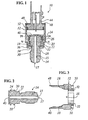
- Figure 1 is a cross-section of a pressure sensor constructed in accordance with embodiments of the present invention, but without the associated electronic components depicted for illustrative purposes.
- Figure 2 is a cross-section of a pressure port constructed in accordance with an embodiment of the present invention.
- Figure 3 is a cross-section of a housing constructed in accordance with embodiments of the present invention.
- Figure 4 is a cross-section of the assembled pressure sensor, taken along line IV-IV in Figure 1.
- Figure 5 is a cross-section of another portion of the assembled pressure sensor in accordance with an embodiment of the present invention, taken along line V-V in Figure 1.
- Figure 6 is a top view of a retaining ring constructed in accordance with an embodiment of the present invention.
- Figure 7 is a schematic cross-section depicting the assembled pressure sensor with electronics in accordance with embodiments of the present invention.
- the present invention addresses and solves problems related to high pressure sensors, including those of reducing costs to the manufacturer, while creating a mechanically sound method of integrating a separate pressure port and housing in a sensor. These are achieved, in the present invention, by the formation of a pressure port machined from relatively smaller diameter stock.
- the pressure port has no internal gaskets or O-rings.
- the end of the pressure port terminates at a diaphragm that is integral with the pressure port. Fluid is therefore prevented from entering inside of the housing which surrounds and securely holds a portion of the pressure port.
- Through mechanical coupling, and configuration of the housing and the pressure port excessive rotation between the port and the housing during high torque installations is prevented. Furthermore, excessive movement on the longitudinal axis between the pressure port and the housing is prevented by the mechanical coupling.
- the high pressure sensor 10 is depicted with a housing 12 and pressure port 14 in an assembled state.
- the pressure port 14 which may be machined from a relatively small diameter cylinder of a suitable material such as high strength stainless steel, has a fluid chamber 15 extending through most of the pressure port 14.
- the fluid chamber 15 opens at a fluid inlet 17.
- the fluid chamber 15 can be made by drilling a borehole (e.g. a 3 mm bore hole, when the diameter of the pressure port is approximately 12 mm).
- the fluid chamber 15 extends, in certain embodiments of the invention, through most of the pressure port 14 but terminates at a diaphragm 40.
- the diaphragm 40 is integral to the pressure port 14. This has a number of advantages, including avoiding the steps of securing a diaphragm to the pressure port, and ensuring that leaks from the pressure sensor into the housing do not occur.
- the diaphragm may be approximately 1 mm thick, although other thicknesses may be employed.
- the pressure port 14 is inserted through a central opening 16 (see Figure 3) of the housing 12 into the position shown in Figure 1, during assembly.
- the housing 12 has a housing shoulder 18 against which an O-ring gland ledge 20 of the port 14 abuts in the assembled position. This limits the movement of the pressure port 14 relative to the housing 12 in the downward axial direction depicted in Figure 1.
- a retaining ring 28 is placed around the pressure port 14 and extends into mating slots 30 of the pressure port 14. Retaining ring 28 also bears against ends 32 of the housing 12. The retaining ring 28 is flexed and biases the pressure port 14 (in a downward direction in Figure 1) to lock the pressure port 14 with respect to the housing 12 in axial direction.
- a top view of an embodiment of the retaining ring 28 is depicted in Figure 6.
- the retaining ring 28 has an opening 29 in its circumference that allows the retaining ring 28 to be slipped around the circumference of the pressure port 14.
- a plastic retaining ring protector 36 over the retaining ring 28.
- the retaining ring protector 36 is press-fit onto the housing 12.
- the retaining ring protector 36 ensures that the end user cannot displace the retaining ring 28 from its installed position without causing visible damage.
- a fixative such as epoxy 34, is inserted into the space created by the retaining ring protector 36 and the housing 12, and secures the retaining ring protector 36 in place. Tins epoxy 34 fills all the space around the retaining ring 28.
- the epoxy 34, or other fixative prevents relative motion and fretting between the retaining ring 28 and the housing 12 under heavy (e.g. 50 Grms) levels of vibration.
- the epoxy 34 provides long-term reliability of the system.
- the epoxy 34 prevents the retaining ring 28 from rubbing material off of the face of the housing 12. Such wear could possibly cause "slop" in the system after periods of heavy vibration. This slop eventually wears down the O-ring leading to water intrusion to the electronics of the sensor 10 inside the housing 12. Fluid sealing is further enhanced by an O-ring 26 that is provided between the O-ring gland 20 of the pressure port and the O-ring gland in the housing 12.
- the retaining ring protector is inserted into a mating gland in the housing 12 and secured in place by crimps that are deformed over the retaining ring protector 36.
- the epoxy 34 provides additional sccurement in this embodiment.
- the pressure port 14 and housing 12 are configured to prevent relative rotation during high-torque installations.
- at least a section of the pressure port 14 has an outer circumference that is a non-circular shape.
- This first section 22 of the pressure port 14 matches the shape of the inner circumference of the housing 12 in that region.
- the pressure port 14 has an approximately square configuration in the first section 22 in an exemplary embodiment.
- the inner circumference of the housing 12 also has an approximately square configuration. Other shapes are contemplated by the invention. These mating configurations, and their non-circular shapes, prevent relative rotation between the pressure port 14 and housing 12.
- Other sections of the pressure port 14 may remain in a circular shape, such as second section 24.
- a cross-section of the circular section of the housing 12 and the pressure port 14, including the O-ring 26, is depicted in Figure 4.
- a connector 44 is provided in the housing 12 and is sealed with O-ring 52 located between connector 44 and the housing 12.
- the connector 44 provides the connections between the electronics inside sensor 10 to electronic components outside the sensor 10.
- the connector 44 is secured to the housing 12 by crimps 48 (shown in an uncrimped position in Figure 1) that are crimped over the shoulders of connector 44.
- the plastic retaining ring 36 is press-fit in position on the housing 12.
- the pressure port 14 in isolation is depicted in cross-section in Figure 2.
- the housing 12 in isolation is depicted in cross-section in Figure 3. Since the housing 12 is not integrally formed from the same piece of material as the pressure port 14, the housing 12 may be made of less expensive material than stainless steel, such as aluminum or other suitable material.
- a piezoresistive die 46 is provided on the diaphragm 40 and contains conventional strain gages that sense the diaphragm stress.
- An ASIC 48 is provided and is connected with the piezoresistive die 46 to a two-lobed flexible circuit 50.
- the flexible circuit 50 is connected to connector pins 53 which serve to connect the electronics within the housing 12 to external components that receive and interpret the sensor signals.
- a plastic wire bond cover 54 covers the wire bonding within the housing 12.
- One of the advantages of the pressure port 14 is the lack of O-rings or gaskets in the pressure inlet 17 leading to the diaphragm 40. This helps to ensure the sealing of the inside of the housing 12 from the environment, and is especially important in light of the very high pressures, such as 10,000 to 30,000 psi, or greater, that the high pressure sensor 10 may be exposed to.
- the present invention provides a multi-piece sensor that reduces the cost of manufacture by machining only the pressure port from high-grade expensive materials.
- the invention ensures that the high pressure sensor has mechanically sound integration of the pressure port and the housing so as to not permit excessive rotation between the court and the housing during high (e.g. 50 Nm) torque installations.
- the inside of the housing is sealed from the environment with the present invention. Excessive movement along the longitudinal axis is also prevented during installation, handling or strong vibrations.
Landscapes
- Physics & Mathematics (AREA)
- General Physics & Mathematics (AREA)
- Measuring Fluid Pressure (AREA)
Applications Claiming Priority (2)
| Application Number | Priority Date | Filing Date | Title |
|---|---|---|---|
| US29644101P | 2001-06-08 | 2001-06-08 | |
| US296441P | 2001-06-08 |
Publications (3)
| Publication Number | Publication Date |
|---|---|
| EP1265061A1 true EP1265061A1 (de) | 2002-12-11 |
| EP1265061B1 EP1265061B1 (de) | 2006-02-01 |
| EP1265061B8 EP1265061B8 (de) | 2006-05-03 |
Family
ID=23142009
Family Applications (1)
| Application Number | Title | Priority Date | Filing Date |
|---|---|---|---|
| EP02011651A Expired - Lifetime EP1265061B8 (de) | 2001-06-08 | 2002-05-29 | Hochdrucksensor mit separatem Druckstutzen und Gehäuse und Verfahren zu dessen Herstellung |
Country Status (3)
| Country | Link |
|---|---|
| US (1) | US6742397B2 (de) |
| EP (1) | EP1265061B8 (de) |
| DE (1) | DE60208948T2 (de) |
Cited By (1)
| Publication number | Priority date | Publication date | Assignee | Title |
|---|---|---|---|---|
| DE102005012686A1 (de) * | 2005-01-14 | 2006-07-27 | Trafag Ag | Drucksensor, darin verwendbarer Verformungskörper und Herstellverfahren dafür |
Families Citing this family (13)
| Publication number | Priority date | Publication date | Assignee | Title |
|---|---|---|---|---|
| DE10034460A1 (de) * | 2000-07-15 | 2002-01-31 | Bosch Gmbh Robert | Hochdrucksensor, Verfahren und Werkzeug zu seiner Herstellung |
| US20050097721A1 (en) * | 2003-11-06 | 2005-05-12 | Bratek Daniel J. | High pressure sensor with knurl press-fit assembly |
| US20060059994A1 (en) * | 2004-09-21 | 2006-03-23 | Honeywell International, Inc. | Carrier to port mechanical interface for a pressure sensor |
| US7086290B2 (en) * | 2004-12-09 | 2006-08-08 | Honeywell International Inc. | Pressure sensor with single deposit adhesive |
| US20070028697A1 (en) * | 2005-08-08 | 2007-02-08 | Honeywell International Inc. | One piece needle and diaphragm assembly |
| US20080191474A1 (en) * | 2007-02-12 | 2008-08-14 | Kotz George J | Tri-Lobed O-Ring Seal |
| US9354132B2 (en) * | 2009-02-12 | 2016-05-31 | Continental Automotive Systems, Inc. | Jointless pressure sensor port |
| US8286496B2 (en) * | 2009-02-17 | 2012-10-16 | Nagano Keiki Co., Ltd. | Fluid pressure sensor incorporating flexible circuit board |
| EP2312290B1 (de) * | 2009-10-16 | 2019-09-25 | First Sensor Mobility GmbH | Drucksensor und dessen Verwendung in einem Fluidtank |
| DE102012222089A1 (de) * | 2012-12-03 | 2014-06-05 | Robert Bosch Gmbh | Drucksensormodul |
| JP6325901B2 (ja) * | 2014-05-30 | 2018-05-16 | 矢崎総業株式会社 | 組み付け方法 |
| US20160033348A1 (en) * | 2014-07-30 | 2016-02-04 | Yi-Lin Motor Parts Co., Ltd. | Pressure transducer |
| US10620071B2 (en) * | 2016-06-29 | 2020-04-14 | Danfoss A/S | Pressure sensor and method for manufacturing a pressure sensor |
Citations (3)
| Publication number | Priority date | Publication date | Assignee | Title |
|---|---|---|---|---|
| US3899766A (en) * | 1974-03-29 | 1975-08-12 | Tyco Laboratories Inc | Pressure transducer |
| EP0352240A1 (de) * | 1988-07-21 | 1990-01-24 | MARELLI AUTRONICA S.p.A. | Wandler für sehr hohen Druck, insbesondere zur Druckmessung einer hydraulischen Flüssigkeit |
| US6050147A (en) * | 1997-12-05 | 2000-04-18 | Delco Electronics Corp. | Pressure sensor assembly |
Family Cites Families (8)
| Publication number | Priority date | Publication date | Assignee | Title |
|---|---|---|---|---|
| US2390103A (en) * | 1943-03-08 | 1945-12-04 | William J Johnson | Union tube connection locking nut |
| US4927188A (en) * | 1988-11-30 | 1990-05-22 | Shipley Company, Inc. | Fitting for connecting a drum to a pipeline |
| US5186501A (en) * | 1991-03-25 | 1993-02-16 | Mano Michael E | Self locking connector |
| US5131690A (en) * | 1991-07-29 | 1992-07-21 | Mano Michael E | Self-locking connector |
| US5472058A (en) * | 1994-04-20 | 1995-12-05 | Smith International, Inc. | Rock bit with mechanical seal |
| US5902478A (en) * | 1997-02-12 | 1999-05-11 | Advanced Performance Technology, Inc. | Filter anti-rotation device |
| US5944190A (en) * | 1997-05-30 | 1999-08-31 | Mallinckrodt Inc. | Radiopharmaceutical capsule safe |
| US6505398B2 (en) * | 2000-12-04 | 2003-01-14 | Kavlico Corporation | Very high pressure miniature sensing and mounting technique |
-
2002
- 2002-05-29 EP EP02011651A patent/EP1265061B8/de not_active Expired - Lifetime
- 2002-05-29 US US10/156,095 patent/US6742397B2/en not_active Expired - Lifetime
- 2002-05-29 DE DE60208948T patent/DE60208948T2/de not_active Expired - Fee Related
Patent Citations (3)
| Publication number | Priority date | Publication date | Assignee | Title |
|---|---|---|---|---|
| US3899766A (en) * | 1974-03-29 | 1975-08-12 | Tyco Laboratories Inc | Pressure transducer |
| EP0352240A1 (de) * | 1988-07-21 | 1990-01-24 | MARELLI AUTRONICA S.p.A. | Wandler für sehr hohen Druck, insbesondere zur Druckmessung einer hydraulischen Flüssigkeit |
| US6050147A (en) * | 1997-12-05 | 2000-04-18 | Delco Electronics Corp. | Pressure sensor assembly |
Cited By (1)
| Publication number | Priority date | Publication date | Assignee | Title |
|---|---|---|---|---|
| DE102005012686A1 (de) * | 2005-01-14 | 2006-07-27 | Trafag Ag | Drucksensor, darin verwendbarer Verformungskörper und Herstellverfahren dafür |
Also Published As
| Publication number | Publication date |
|---|---|
| US20020184955A1 (en) | 2002-12-12 |
| DE60208948D1 (de) | 2006-04-13 |
| EP1265061B1 (de) | 2006-02-01 |
| US6742397B2 (en) | 2004-06-01 |
| DE60208948T2 (de) | 2006-10-26 |
| EP1265061B8 (de) | 2006-05-03 |
Similar Documents
| Publication | Publication Date | Title |
|---|---|---|
| US6742397B2 (en) | High pressure sensor with separate pressure port and housing and method for making the same | |
| US6928880B2 (en) | High pressure sensor | |
| US7086412B2 (en) | Snap-in grommet for a valve steam assembly | |
| EP0621470B1 (de) | Ein Zylinderdrucksensor | |
| US4982608A (en) | High-pressure transducer | |
| EP0692416B1 (de) | Bremsflüssigkeits-Drucksteuergerät | |
| EP2331852A2 (de) | Kompressionssensordichtung und konstruktionsverfahren dafür | |
| US7086411B2 (en) | Snap-in grommet for a valve stem assembly | |
| EP1335195A1 (de) | Einsatz gespritzte Einheit eines Druckwandlers mit einem Druckgefäss | |
| CA2245764C (en) | Screw-on pressure medium-actuated working cylinder with closure components for coupling the cylinder tube | |
| US6050147A (en) | Pressure sensor assembly | |
| EP3224449B1 (de) | Unterwasser-sensorhub | |
| CN106051332A (zh) | 具有联接接头的测量仪器 | |
| JP6480375B2 (ja) | 圧力センサ | |
| JPH04223242A (ja) | 圧力媒質測定センサー | |
| US7895897B2 (en) | Sensor assembly and use of a sensor assembly | |
| US6575048B1 (en) | Sensor positioning assembly | |
| JP3966065B2 (ja) | 圧力センサ | |
| JP2007187609A (ja) | 圧力センサの取付構造 | |
| US20050126297A1 (en) | Pressure sensor element having an integrated sealing surface | |
| KR100481237B1 (ko) | 링너트를구비한압축슬리브 | |
| US12436055B2 (en) | Pressure transducer for use in charged media | |
| KR200285966Y1 (ko) | 온도 센서 하우징 | |
| JP2002340637A (ja) | 電磁流量計 | |
| EP1368880B1 (de) | Verbesserungen in elektromotorisch angetriebenen hydraulikpumpen |
Legal Events
| Date | Code | Title | Description |
|---|---|---|---|
| PUAI | Public reference made under article 153(3) epc to a published international application that has entered the european phase |
Free format text: ORIGINAL CODE: 0009012 |
|
| AK | Designated contracting states |
Kind code of ref document: A1 Designated state(s): AT BE CH CY DE DK ES FI FR GB GR IE IT LI LU MC NL PT SE TR |
|
| AX | Request for extension of the european patent |
Free format text: AL;LT;LV;MK;RO;SI |
|
| 17P | Request for examination filed |
Effective date: 20030611 |
|
| AKX | Designation fees paid |
Designated state(s): DE FR GB |
|
| 17Q | First examination report despatched |
Effective date: 20040211 |
|
| GRAP | Despatch of communication of intention to grant a patent |
Free format text: ORIGINAL CODE: EPIDOSNIGR1 |
|
| GRAS | Grant fee paid |
Free format text: ORIGINAL CODE: EPIDOSNIGR3 |
|
| GRAA | (expected) grant |
Free format text: ORIGINAL CODE: 0009210 |
|
| AK | Designated contracting states |
Kind code of ref document: B1 Designated state(s): DE FR GB |
|
| REG | Reference to a national code |
Ref country code: GB Ref legal event code: FG4D |
|
| REG | Reference to a national code |
Ref country code: GB Ref legal event code: ERR Free format text: NOTIFICATION HAS NOW BEEN RECEIVED FROM THE EUROPEAN PATENT OFFICE THAT THE CORRECT NAME IS: HONEYWELL INTERNATIONAL, INC. THIS CORRECTION WAS PUBLISHED IN THE EUROPEAN PATENT BULLETIN 06/12 DATED 20060222 |
|
| RAP2 | Party data changed (patent owner data changed or rights of a patent transferred) |
Owner name: HONEYWELL INTERNATIONAL, INC. |
|
| REF | Corresponds to: |
Ref document number: 60208948 Country of ref document: DE Date of ref document: 20060413 Kind code of ref document: P |
|
| ET | Fr: translation filed | ||
| PLBE | No opposition filed within time limit |
Free format text: ORIGINAL CODE: 0009261 |
|
| STAA | Information on the status of an ep patent application or granted ep patent |
Free format text: STATUS: NO OPPOSITION FILED WITHIN TIME LIMIT |
|
| 26N | No opposition filed |
Effective date: 20061103 |
|
| PGFP | Annual fee paid to national office [announced via postgrant information from national office to epo] |
Ref country code: DE Payment date: 20070531 Year of fee payment: 6 |
|
| PGFP | Annual fee paid to national office [announced via postgrant information from national office to epo] |
Ref country code: GB Payment date: 20070410 Year of fee payment: 6 |
|
| PGFP | Annual fee paid to national office [announced via postgrant information from national office to epo] |
Ref country code: FR Payment date: 20070503 Year of fee payment: 6 |
|
| GBPC | Gb: european patent ceased through non-payment of renewal fee |
Effective date: 20080529 |
|
| REG | Reference to a national code |
Ref country code: FR Ref legal event code: ST Effective date: 20090119 |
|
| PG25 | Lapsed in a contracting state [announced via postgrant information from national office to epo] |
Ref country code: DE Free format text: LAPSE BECAUSE OF NON-PAYMENT OF DUE FEES Effective date: 20081202 Ref country code: FR Free format text: LAPSE BECAUSE OF NON-PAYMENT OF DUE FEES Effective date: 20080602 |
|
| PG25 | Lapsed in a contracting state [announced via postgrant information from national office to epo] |
Ref country code: GB Free format text: LAPSE BECAUSE OF NON-PAYMENT OF DUE FEES Effective date: 20080529 |