EP1266143B2 - Wireless, intrinsically safe valve - Google Patents
Wireless, intrinsically safe valve Download PDFInfo
- Publication number
- EP1266143B2 EP1266143B2 EP01918848A EP01918848A EP1266143B2 EP 1266143 B2 EP1266143 B2 EP 1266143B2 EP 01918848 A EP01918848 A EP 01918848A EP 01918848 A EP01918848 A EP 01918848A EP 1266143 B2 EP1266143 B2 EP 1266143B2
- Authority
- EP
- European Patent Office
- Prior art keywords
- valve
- signal
- pilot
- optical
- transmitter
- Prior art date
- Legal status (The legal status is an assumption and is not a legal conclusion. Google has not performed a legal analysis and makes no representation as to the accuracy of the status listed.)
- Expired - Lifetime
Links
Images



Classifications
-
- F—MECHANICAL ENGINEERING; LIGHTING; HEATING; WEAPONS; BLASTING
- F15—FLUID-PRESSURE ACTUATORS; HYDRAULICS OR PNEUMATICS IN GENERAL
- F15B—SYSTEMS ACTING BY MEANS OF FLUIDS IN GENERAL; FLUID-PRESSURE ACTUATORS, e.g. SERVOMOTORS; DETAILS OF FLUID-PRESSURE SYSTEMS, NOT OTHERWISE PROVIDED FOR
- F15B13/00—Details of servomotor systems ; Valves for servomotor systems
- F15B13/02—Fluid distribution or supply devices characterised by their adaptation to the control of servomotors
- F15B13/04—Fluid distribution or supply devices characterised by their adaptation to the control of servomotors for use with a single servomotor
- F15B13/042—Fluid distribution or supply devices characterised by their adaptation to the control of servomotors for use with a single servomotor operated by fluid pressure
- F15B13/0426—Fluid distribution or supply devices characterised by their adaptation to the control of servomotors for use with a single servomotor operated by fluid pressure with fluid-operated pilot valves, i.e. multiple stage valves
-
- F—MECHANICAL ENGINEERING; LIGHTING; HEATING; WEAPONS; BLASTING
- F15—FLUID-PRESSURE ACTUATORS; HYDRAULICS OR PNEUMATICS IN GENERAL
- F15B—SYSTEMS ACTING BY MEANS OF FLUIDS IN GENERAL; FLUID-PRESSURE ACTUATORS, e.g. SERVOMOTORS; DETAILS OF FLUID-PRESSURE SYSTEMS, NOT OTHERWISE PROVIDED FOR
- F15B13/00—Details of servomotor systems ; Valves for servomotor systems
- F15B13/02—Fluid distribution or supply devices characterised by their adaptation to the control of servomotors
- F15B13/04—Fluid distribution or supply devices characterised by their adaptation to the control of servomotors for use with a single servomotor
- F15B13/042—Fluid distribution or supply devices characterised by their adaptation to the control of servomotors for use with a single servomotor operated by fluid pressure
- F15B13/043—Fluid distribution or supply devices characterised by their adaptation to the control of servomotors for use with a single servomotor operated by fluid pressure with electrically-controlled pilot valves
-
- F—MECHANICAL ENGINEERING; LIGHTING; HEATING; WEAPONS; BLASTING
- F15—FLUID-PRESSURE ACTUATORS; HYDRAULICS OR PNEUMATICS IN GENERAL
- F15B—SYSTEMS ACTING BY MEANS OF FLUIDS IN GENERAL; FLUID-PRESSURE ACTUATORS, e.g. SERVOMOTORS; DETAILS OF FLUID-PRESSURE SYSTEMS, NOT OTHERWISE PROVIDED FOR
- F15B21/00—Common features of fluid actuator systems; Fluid-pressure actuator systems or details thereof, not covered by any other group of this subclass
- F15B21/08—Servomotor systems incorporating electrically operated control means
Definitions
- the present invention relates generally to intrinsically safe valves and, more particularly, to valves that employ a piezo-electric element that operates using minimal electrical energy.
- Chemical management systems require significant consideration towards minimizing the potential for igniting such chemicals. Chemical management systems typically are designed so that arcing and sparks which often result from connecting and disconnecting electrical circuits is minimized. Presently, such chemical management systems utilize expensive wiring and switch elements in order to achieve this goal.
- the valve controller comprises a control part, a positioner part and a battery.
- the control part comprises an interface, a microprocessor, a D/A converter, an electric-pneumatic converter, a return lever, an angle detector and an A/D converter.
- the electric-pneumatic converter receives pneumatic pressure and comprises a piezoelectric flapper, a nozzle and a pilot valve.
- a valve system employs a low voltage element, such as a piezo-electric element, to activate a fluid flow valve so as to use a minimal amount of electrical energy.
- the piezo-electric element activates a pilot pressure valve, which allows a control fluid to pass to a main control valve.
- the control fluid causes the main control valve to activate a pneumatic rotary operator, which is turn operates the fluid flow valve.
- a switching assembly is employed to activate the piezo-electric element.
- the switching assembly can include various types of switching devices, such as RF switching devices, optical switching devices, infrared switching devices and low voltage electrical switching devices, to allow the valve to be controlled from a remote location.
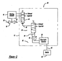
- FIG. 1 is a plan view of an intrinsically safe valve system 10.
- the valve system 10 includes a valve activation assembly 12, a transmitter 14, a working element 16 and a fluid valve 18.
- the transmitter 14 transmits a signal 24 from an antenna 26 that is received by an antenna 30 associated with the valve assembly 12.
- the signal 24 is an RF signal, but as will be discussed in more detail below, other signals can be used, such as optical signals, infrared signals, and low voltage signals.
- the signal 24 may be encoded by the transmitter 14 so that only a particular valve assembly 12 operates in response to the signal 24.
- the valve assembly 12 may be addressable to distinguish a particular valve assembly 12 from other valve assemblies.
- valve assembly 12 When the valve assembly 12 receives the signal 24, it activates the working element 16, which opens or closes the fluid valve 18 depending on its normal state.
- the valve 18 controls the flow of chemicals between a first side 20 and a second side 22.
- the valve 18 can be any type of actuator that operates under low voltage. Particularly, the valve 18 can be any actuation device that can benefit from the system described herein.
- the receiver 28 includes a detector 30 that detects the signal 24 from the antenna 30.
- a battery 32 provides electrical energy to the receiver 28.
- the receiver 28 includes a non-contacting switch 34 responsive to the signal 24 from the antenna 30. If the transmitter 14 encodes the signal 24, the non-contacting switch 34 responds only if the receiver 28 is the properly addressed receiver.
- the pilot valve 36 includes a piezo-electric switch assembly 38 attached to a valve body 40 of the valve 36.
- the switch assembly 38 includes a piezo-electric element whose structural configuration changes in response to a voltage, as is well understood in the art .
- the piezo-electric element can be any piezo element suitable for the purposes described herein. In alternate embodiments, the piezo-electric element can be other types of low voltage elements suitable for the purposes described herein, such as those that employ bending element technology, such as ceramic elements.
- the valve 36 is a two position valve which supplies input air at a pilot pressure to a pilot line 42.
- the assembly 38 includes a baffle (not shown) which deflects upon application of a voltage. Deflection of the baffle opens a small orifice to allow air at the pilot pressure to be applied to the pilot line 42, which is then applied to a main spool or poppet valve 44.
- the pilot valve 36 is embodied as a commercial available valve.
- the main valve 44 controls application of input air and exhaust to the working element 16.
- the main valve 44 applies input air to displace the working element 16.
- the working element 16 may be embodied as a pneumatic, rotary operator for the valve 18.
- the valve 18 may be embodied as a butterfly valve so that displacement of the working element 16 opens and closes the valve 18.
- the pilot valve 36 cuts off the supply of pilot pressure to the pilot line 42. This in turn displaces the main valve 44 to a deactuated position, which displaces the working element 16 to its initial position, thereby closing the valve 18.
- Figure 2 depicts an intrinsically safe valve system 50, which is arranged similarly to the valve system 10, and like reference numerals will be used to designate like elements. Such like elements will not be described with respect to Figure 2 as they operate as described with respect to Figure 1 .
- an optical actuation system 52 replaces the transmitter 14 and the receiver 28 of the system 10.
- the system 52 includes a fiber optic switch 54 that outputs an optical signal on a fiber optic cable 56.
- the fiber optic cable 56 applies the optical signal to a fiber optic detector 58.
- the fiber optic detector 58 converts the optical signal from the switch 54 to a voltage for operating the assembly 38 of the pilot valve 36.
- the fiber optic detector 58 outputs the electrical signal on conductors 60.
- utilizing a piezo-electric element and the pilot valve 36 eliminates the opportunity for arcing due to electrical switch connection and disconnection. Only a minimal amount of electrical energy is needed to actuate the pilot valve 36, thus providing an intrinsically safe valve system. Further yet, because the receiver 28 and the assembly 38 only require a minimal amount of energy, the battery 32 provides substantial battery life for operating the valve system 10 over an extended period of time. With respect to Figure 2 , the battery 32 may be eliminated because the optical signal provide sufficient voltage for operating the assembly 38.
- FIG. 3 is a schematic block diagram of a valve switching system 70 that can replace certain switching devices of the valve systems 10 and 50, as will become apparent from the discussion herein.
- the valve switching system 70 can replace the transmitter 14 and the receiver 28 in the system 10, and replace the optical switch 54 and the fiber optic detector 58 in the system 50.
- the pilot valve 36, the main valve 44, the working element 16 and the fluid valve 18 would operate in the manner discussed above.
- the system 70 includes a control board 72 that controls the piezo-electric element within the assembly 38.
- the valve 18 is open or closed, depending on its normal position, by an optical signal from a light source 74.
- the light source 74 can be any selectively activated light source suitable for the purposes described herein.
- the optical signal generated by the light source 74 propagates down optical fibers 76 arranged in a fiber bundle 78. Light emitted from the ends of the fibers 76 opposite the source 74 is received by a plurality of solar cells 80 arranged in a cell bank 82.
- the solar cells 80 convert the optical energy to an electrical signal that is provided on line 84.
- the electrical signal on line 84 is amplified by a DC-DC converter circuit 86 to amplify the signal level suitable for a particular application.
- the DC-DC converter circuit 86 amplifies the.signal level to 7.5 volts.
- the converter circuit 86 is shown by way of a non-limiting example in that any amplifier circuit suitable for the purposes described herein can be used.
- the amplified electrical signal on line 84 is then sent to the control board 72 that activates the piezo-electric element to switch the pilot valve 36 in the manner as discussed above.
- the solar cells 80, the converter circuit 86 and the control board 72 could be internal to the assembly 38.
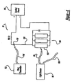
- FIG 4 is a schematic block diagram of an inventive valve switching assembly 92 that is a variation of the switching assembly 70 discussed above.
- the switching assembly 92 powers a control board 94 to control the piezo-electric element within the assembly 38.
- a 1.2 volt signal is used to control the piezo-electric element.
- the system 92 has particular application where a single light source powers many low voltage valve assemblies, and a separate low power optical signal is used to independently control each separate valve.
- a light source 96 provides an optical signal on a plurality of optical fibers 98 and 100, where the optical fiber 98 powers the control board 94 and the fiber optical cable 100 powers another valve switching assembly (not shown).
- the light source 96 can be any light source capable of providing optical signals to a plurality of switching assemblies consistent with the discussion herein.
- the light source 96 controls two separate valve switching assemblies in this embodiment, but as will be appreciated by those skilled in the art, more optical fibers connected to the light source 96 can be provided to control more valve switching assemblies.
- the light source 96 is maintained on so optical power is continually available to any of the several valve switching assemblies that may at any time require optical power.
- the optical signal on the fiber cable 98 that is emitted from an end of the cable 98 opposite the source 90 is received by a plurality of solar cells 104 arranged in a solar cell bank 106.
- the solar cells 104 convert the light energy to electrical energy available on line 108.
- a photodiode 110 is positioned in the electrical line 108, and conducts when it receives an optical signal.
- a fiber transmitter 112 such as an LED, is activated to provide an optical signal on a fiber optical cable 114.
- the photodiode 110 receives the light from an end of the cable 114 opposite the transmitter 112, and conducts so that the electrical signal generated by the solar cells 104 activates the control board 94.
- the control board 94 activates the piezo-electric element in the assembly 38 to control the pilot valve 36, as discussed above.
- the solar cells 104, the photodiode 110 and the control board 94 can be internal to the assembly 38.
- FIG. 5 shows a schematic block diagram of another valve switching system 120 for activating the valve 18 in the manner discussed herein.
- the system 120 includes a control board 122 that operates with a 1.2 volt signal to activate the piezo-electric element in the assembly 38.
- the switching system 120 includes an optical transmitter circuit 124 that includes a manual switch 126, a DC voltage source 128, for example a 9 volt DC source, and a fiber transmitter 130, such as an LED. When the switch 126 is closed, the voltage provided by the source 128 causes the transmitter 130 to transmit light down a fiber optic cable 132.
- the system 120 further includes a switch assembly 136 including a DC voltage source 138, such as a 1.5 DC voltage source, and a photodiode 140.
- a DC voltage source 138 such as a 1.5 DC voltage source
- a photodiode 140 When the photodiode 140 receives light from an end of the optical cable 132 opposite the transmitter 130, it conducts which causes the DC voltage from the source 138 to energize the control board 122.
- the control board 122 activates the piezo-electric element in the assembly 38 which controls the pilot valve 36.
- the switch assembly 136 and the control board 122 can be internal to the assembly 38.
- Figure 6 shows a schematic block diagram of a valve switching system 144 having a control board 146 that is the same as the control board 122, and a switch assembly 148 similar to the switch assembly 136.
- the switch assembly 148 includes a DC voltage source 150 and an opto-coupler 152 that replaces the photodiode 140.
- the opto-coupler 152 receives a low voltage signal from a suitable voltage source 154 that causes the opto-coupler 152 to conduct and energize the control board 146.
- FIG. 7 is a schematic block diagram of a valve switching system 158 that includes a control board 160 that is the same as the control boards 122 and 146 above, and a switch assembly 162 that is similar to the switch assemblies 136 and 148.
- the switch assembly 162 includes a DC voltage source 164, a capacitor 166 and an infrared source 168. A low voltage signal is applied to the infrared source 168 that causes the capacitor 166 to conduct which energizes the control board 160.
Landscapes
- Engineering & Computer Science (AREA)
- Physics & Mathematics (AREA)
- Fluid Mechanics (AREA)
- Mechanical Engineering (AREA)
- General Engineering & Computer Science (AREA)
- Analytical Chemistry (AREA)
- Chemical & Material Sciences (AREA)
- Fluid-Driven Valves (AREA)
- Electrically Driven Valve-Operating Means (AREA)
- Switch Cases, Indication, And Locking (AREA)
- Switches Operated By Changes In Physical Conditions (AREA)
- Servomotors (AREA)
- Circuits Of Receivers In General (AREA)
- Optical Communication System (AREA)
Applications Claiming Priority (3)
| Application Number | Priority Date | Filing Date | Title |
|---|---|---|---|
| US19106600P | 2000-03-21 | 2000-03-21 | |
| US191066P | 2000-03-21 | ||
| PCT/US2001/008869 WO2001071198A2 (en) | 2000-03-21 | 2001-03-20 | Wireless, intrinsically safe valve |
Publications (3)
| Publication Number | Publication Date |
|---|---|
| EP1266143A2 EP1266143A2 (en) | 2002-12-18 |
| EP1266143B1 EP1266143B1 (en) | 2005-08-24 |
| EP1266143B2 true EP1266143B2 (en) | 2010-01-20 |
Family
ID=22704000
Family Applications (1)
| Application Number | Title | Priority Date | Filing Date |
|---|---|---|---|
| EP01918848A Expired - Lifetime EP1266143B2 (en) | 2000-03-21 | 2001-03-20 | Wireless, intrinsically safe valve |
Country Status (10)
| Country | Link |
|---|---|
| EP (1) | EP1266143B2 (pt) |
| JP (1) | JP4798922B2 (pt) |
| CN (1) | CN1288355C (pt) |
| AU (1) | AU2001245873A1 (pt) |
| BR (1) | BR0102829B1 (pt) |
| CA (1) | CA2356753C (pt) |
| DE (1) | DE60112904T3 (pt) |
| ES (1) | ES2247084T3 (pt) |
| MX (1) | MXPA01007353A (pt) |
| WO (1) | WO2001071198A2 (pt) |
Cited By (1)
| Publication number | Priority date | Publication date | Assignee | Title |
|---|---|---|---|---|
| US10177565B2 (en) | 2014-01-07 | 2019-01-08 | Yokogawa Electric Corporation | Contact signal converter |
Families Citing this family (6)
| Publication number | Priority date | Publication date | Assignee | Title |
|---|---|---|---|---|
| DE102006041601A1 (de) * | 2006-09-05 | 2008-03-06 | ITW Oberflächentechnik GmbH & Co. KG | Steuereinrichtung eines Druckluftmotors, insbesondere in Kombination mit einer Pumpe und einer Sprühbeschichtungsanlage |
| US8814133B2 (en) * | 2011-06-23 | 2014-08-26 | General Equipment And Manufacturing Company, Inc. | Automatic speed searching device and method for a partial stroke test of a control valve |
| DE102013007927B4 (de) * | 2013-05-10 | 2014-12-24 | Hoerbiger Automatisierungstechnik Holding Gmbh | Antriebseinheit |
| GB201313804D0 (en) * | 2013-08-01 | 2013-09-18 | Moog Controls Ltd | Improvements in hydraulic servovalves |
| US9958880B2 (en) | 2015-09-16 | 2018-05-01 | Fisher Controls International Llc | Wireless valve actuator system and method |
| SE541705C2 (en) * | 2016-10-10 | 2019-12-03 | Aaloe Ab | An implement and method for controlling the implement |
Citations (5)
| Publication number | Priority date | Publication date | Assignee | Title |
|---|---|---|---|---|
| DE2842808A1 (de) † | 1977-10-11 | 1979-04-12 | Hills Mccanna Co | Ventil-betaetigungsorgan |
| JPS5569375A (en) † | 1978-11-20 | 1980-05-24 | Tlv Co Ltd | Electric valve |
| US5101862A (en) † | 1991-08-08 | 1992-04-07 | Leete Barrett C | Rotary actuator and valve control system |
| JPH08226402A (ja) † | 1995-02-21 | 1996-09-03 | Fuji Electric Co Ltd | 弁コントローラ |
| DE4105062C2 (de) † | 1990-09-19 | 1997-01-23 | Helmut Prof Dipl Ing Hoenicke | Elektropneumatischer Stellungsregler mit Pulsbreitenansteuerung |
Family Cites Families (10)
| Publication number | Priority date | Publication date | Assignee | Title |
|---|---|---|---|---|
| CH563532A5 (pt) * | 1973-03-14 | 1975-06-30 | Buehler Ag Geb | |
| US4443853A (en) * | 1981-03-25 | 1984-04-17 | United Technologies Corporation | Optical digital servo control system |
| US4412355A (en) * | 1981-10-14 | 1983-10-25 | Hughes Aircraft Company | Push-button operated electrical power source for an optical communication link |
| JPH02190683A (ja) * | 1989-01-18 | 1990-07-26 | Toshiba Corp | パイロット弁装置 |
| DE4116570A1 (de) * | 1991-05-21 | 1992-11-26 | Herion Werke Kg | Verfahren und anordnung zum ansteuern von ventilen |
| US5447286A (en) * | 1994-01-21 | 1995-09-05 | Deka Products Limited Partnership | High flow valve |
| US5543627A (en) * | 1994-09-23 | 1996-08-06 | The Boeing Company | Method for maximizing the solar cell OPTO-electronic conversion efficiency in optically controlled hydraulic actuators |
| US5709245A (en) * | 1994-09-23 | 1998-01-20 | The Boeing Company | Optically controlled actuator |
| US5706852A (en) * | 1995-10-03 | 1998-01-13 | Deville; Wayne E. | Multi-orifice plate carrier and fitting with positioner, differential selector and horizontal adjusting bar |
| AT407432B (de) * | 1998-03-18 | 2001-03-26 | Hygrama Ag | Piezoelektrisches ventil |
-
2001
- 2001-03-20 BR BRPI0102829-4A patent/BR0102829B1/pt not_active IP Right Cessation
- 2001-03-20 WO PCT/US2001/008869 patent/WO2001071198A2/en not_active Ceased
- 2001-03-20 CN CN 01800079 patent/CN1288355C/zh not_active Expired - Fee Related
- 2001-03-20 AU AU2001245873A patent/AU2001245873A1/en not_active Abandoned
- 2001-03-20 ES ES01918848T patent/ES2247084T3/es not_active Expired - Lifetime
- 2001-03-20 DE DE60112904T patent/DE60112904T3/de not_active Expired - Lifetime
- 2001-03-20 CA CA002356753A patent/CA2356753C/en not_active Expired - Fee Related
- 2001-03-20 MX MXPA01007353A patent/MXPA01007353A/es active IP Right Grant
- 2001-03-20 JP JP2001569152A patent/JP4798922B2/ja not_active Expired - Fee Related
- 2001-03-20 EP EP01918848A patent/EP1266143B2/en not_active Expired - Lifetime
Patent Citations (5)
| Publication number | Priority date | Publication date | Assignee | Title |
|---|---|---|---|---|
| DE2842808A1 (de) † | 1977-10-11 | 1979-04-12 | Hills Mccanna Co | Ventil-betaetigungsorgan |
| JPS5569375A (en) † | 1978-11-20 | 1980-05-24 | Tlv Co Ltd | Electric valve |
| DE4105062C2 (de) † | 1990-09-19 | 1997-01-23 | Helmut Prof Dipl Ing Hoenicke | Elektropneumatischer Stellungsregler mit Pulsbreitenansteuerung |
| US5101862A (en) † | 1991-08-08 | 1992-04-07 | Leete Barrett C | Rotary actuator and valve control system |
| JPH08226402A (ja) † | 1995-02-21 | 1996-09-03 | Fuji Electric Co Ltd | 弁コントローラ |
Cited By (1)
| Publication number | Priority date | Publication date | Assignee | Title |
|---|---|---|---|---|
| US10177565B2 (en) | 2014-01-07 | 2019-01-08 | Yokogawa Electric Corporation | Contact signal converter |
Also Published As
| Publication number | Publication date |
|---|---|
| CN1380948A (zh) | 2002-11-20 |
| AU2001245873A1 (en) | 2001-10-03 |
| MXPA01007353A (es) | 2003-06-06 |
| ES2247084T3 (es) | 2006-03-01 |
| BR0102829A (pt) | 2002-04-23 |
| JP4798922B2 (ja) | 2011-10-19 |
| BR0102829B1 (pt) | 2011-09-06 |
| EP1266143B1 (en) | 2005-08-24 |
| CA2356753C (en) | 2006-10-03 |
| DE60112904T3 (de) | 2010-08-05 |
| WO2001071198A3 (en) | 2002-04-18 |
| CN1288355C (zh) | 2006-12-06 |
| DE60112904D1 (de) | 2005-09-29 |
| CA2356753A1 (en) | 2001-09-21 |
| DE60112904T2 (de) | 2006-06-08 |
| WO2001071198A2 (en) | 2001-09-27 |
| JP2003528269A (ja) | 2003-09-24 |
| EP1266143A2 (en) | 2002-12-18 |
Similar Documents
| Publication | Publication Date | Title |
|---|---|---|
| US6685159B1 (en) | Wireless, intrinsically safe valve | |
| CA1095939A (en) | Remote control system for mining machines | |
| EP1266143B2 (en) | Wireless, intrinsically safe valve | |
| EP1080323B1 (en) | Electrically controllable valve | |
| US4998294A (en) | Opto-electrical power transmission and control system | |
| US5651385A (en) | Servo drive operated by a pressure medium | |
| EP0182259A1 (en) | Safety apparatus for an atomic absorption spectrophotometer burner | |
| US6419478B1 (en) | Stepper motor driving a linear actuator operating a pressure control regulator | |
| EP1192715B1 (en) | Opto-electrical actuation system and method | |
| WO1998039547A3 (en) | Integrated power and control system | |
| KR930022018A (ko) | 공조시스템 | |
| KR102476405B1 (ko) | 오토 밸브 시스템 | |
| NO842080L (no) | Ventil-omformer/innstiller med fjerntilbakekopling og hukommelse | |
| EP1292786B1 (en) | Intrinsically safe microprocessor controlled pressure regulator | |
| US3402737A (en) | Fluid pressure modulating servo valve | |
| US5469877A (en) | Electric to pneumatic transducer | |
| US5224684A (en) | Blowback operated fluid valve | |
| CN214198661U (zh) | 一种燃气炉头的应急调节阀结构 | |
| NO180126B (no) | Styrekrets | |
| US7643266B2 (en) | Trigger circuit for an electromagnetic actuator | |
| EP4677422A1 (en) | Load adapter module for wireless discrete input/output field device | |
| NO20231259A1 (pt) | ||
| JPS6272977A (ja) | 光利用の液体荷役制御装置 | |
| KR20040054021A (ko) | 건설중장비의 리모트콘트롤밸브의 2차신호발생장치 |
Legal Events
| Date | Code | Title | Description |
|---|---|---|---|
| PUAI | Public reference made under article 153(3) epc to a published international application that has entered the european phase |
Free format text: ORIGINAL CODE: 0009012 |
|
| 17P | Request for examination filed |
Effective date: 20010630 |
|
| AK | Designated contracting states |
Kind code of ref document: A2 Designated state(s): AT BE CH CY DE DK ES FI FR GB GR IE IT LI LU MC NL PT SE TR |
|
| AX | Request for extension of the european patent |
Free format text: AL;LT;LV;MK;RO;SI |
|
| 17Q | First examination report despatched |
Effective date: 20040218 |
|
| RBV | Designated contracting states (corrected) |
Designated state(s): DE ES FR GB IT |
|
| GRAP | Despatch of communication of intention to grant a patent |
Free format text: ORIGINAL CODE: EPIDOSNIGR1 |
|
| GRAS | Grant fee paid |
Free format text: ORIGINAL CODE: EPIDOSNIGR3 |
|
| GRAA | (expected) grant |
Free format text: ORIGINAL CODE: 0009210 |
|
| AK | Designated contracting states |
Kind code of ref document: B1 Designated state(s): DE ES FR GB IT |
|
| REG | Reference to a national code |
Ref country code: GB Ref legal event code: FG4D |
|
| REF | Corresponds to: |
Ref document number: 60112904 Country of ref document: DE Date of ref document: 20050929 Kind code of ref document: P |
|
| REG | Reference to a national code |
Ref country code: ES Ref legal event code: FG2A Ref document number: 2247084 Country of ref document: ES Kind code of ref document: T3 |
|
| ET | Fr: translation filed | ||
| PLBI | Opposition filed |
Free format text: ORIGINAL CODE: 0009260 |
|
| 26 | Opposition filed |
Opponent name: FESTO AG & CO Effective date: 20060522 |
|
| PLAX | Notice of opposition and request to file observation + time limit sent |
Free format text: ORIGINAL CODE: EPIDOSNOBS2 |
|
| PLBB | Reply of patent proprietor to notice(s) of opposition received |
Free format text: ORIGINAL CODE: EPIDOSNOBS3 |
|
| PGFP | Annual fee paid to national office [announced via postgrant information from national office to epo] |
Ref country code: ES Payment date: 20080317 Year of fee payment: 8 |
|
| PGFP | Annual fee paid to national office [announced via postgrant information from national office to epo] |
Ref country code: GB Payment date: 20080211 Year of fee payment: 8 Ref country code: IT Payment date: 20080317 Year of fee payment: 8 |
|
| PGFP | Annual fee paid to national office [announced via postgrant information from national office to epo] |
Ref country code: FR Payment date: 20080307 Year of fee payment: 8 |
|
| GBPC | Gb: european patent ceased through non-payment of renewal fee |
Effective date: 20090320 |
|
| PUAH | Patent maintained in amended form |
Free format text: ORIGINAL CODE: 0009272 |
|
| STAA | Information on the status of an ep patent application or granted ep patent |
Free format text: STATUS: PATENT MAINTAINED AS AMENDED |
|
| REG | Reference to a national code |
Ref country code: FR Ref legal event code: ST Effective date: 20091130 |
|
| 27A | Patent maintained in amended form |
Effective date: 20100120 |
|
| AK | Designated contracting states |
Kind code of ref document: B2 Designated state(s): DE ES FR GB IT |
|
| PG25 | Lapsed in a contracting state [announced via postgrant information from national office to epo] |
Ref country code: GB Free format text: LAPSE BECAUSE OF NON-PAYMENT OF DUE FEES Effective date: 20090320 Ref country code: FR Free format text: LAPSE BECAUSE OF NON-PAYMENT OF DUE FEES Effective date: 20091123 |
|
| PG25 | Lapsed in a contracting state [announced via postgrant information from national office to epo] |
Ref country code: ES Free format text: LAPSE BECAUSE OF FAILURE TO SUBMIT A TRANSLATION OF THE DESCRIPTION OR TO PAY THE FEE WITHIN THE PRESCRIBED TIME-LIMIT Effective date: 20100501 |
|
| PG25 | Lapsed in a contracting state [announced via postgrant information from national office to epo] |
Ref country code: IT Free format text: LAPSE BECAUSE OF NON-PAYMENT OF DUE FEES Effective date: 20090320 |
|
| PG25 | Lapsed in a contracting state [announced via postgrant information from national office to epo] |
Ref country code: ES Free format text: LAPSE BECAUSE OF FAILURE TO SUBMIT A TRANSLATION OF THE DESCRIPTION OR TO PAY THE FEE WITHIN THE PRESCRIBED TIME-LIMIT Effective date: 20090321 |
|
| PGFP | Annual fee paid to national office [announced via postgrant information from national office to epo] |
Ref country code: DE Payment date: 20150317 Year of fee payment: 15 |
|
| REG | Reference to a national code |
Ref country code: DE Ref legal event code: R119 Ref document number: 60112904 Country of ref document: DE |
|
| PG25 | Lapsed in a contracting state [announced via postgrant information from national office to epo] |
Ref country code: DE Free format text: LAPSE BECAUSE OF NON-PAYMENT OF DUE FEES Effective date: 20161001 |